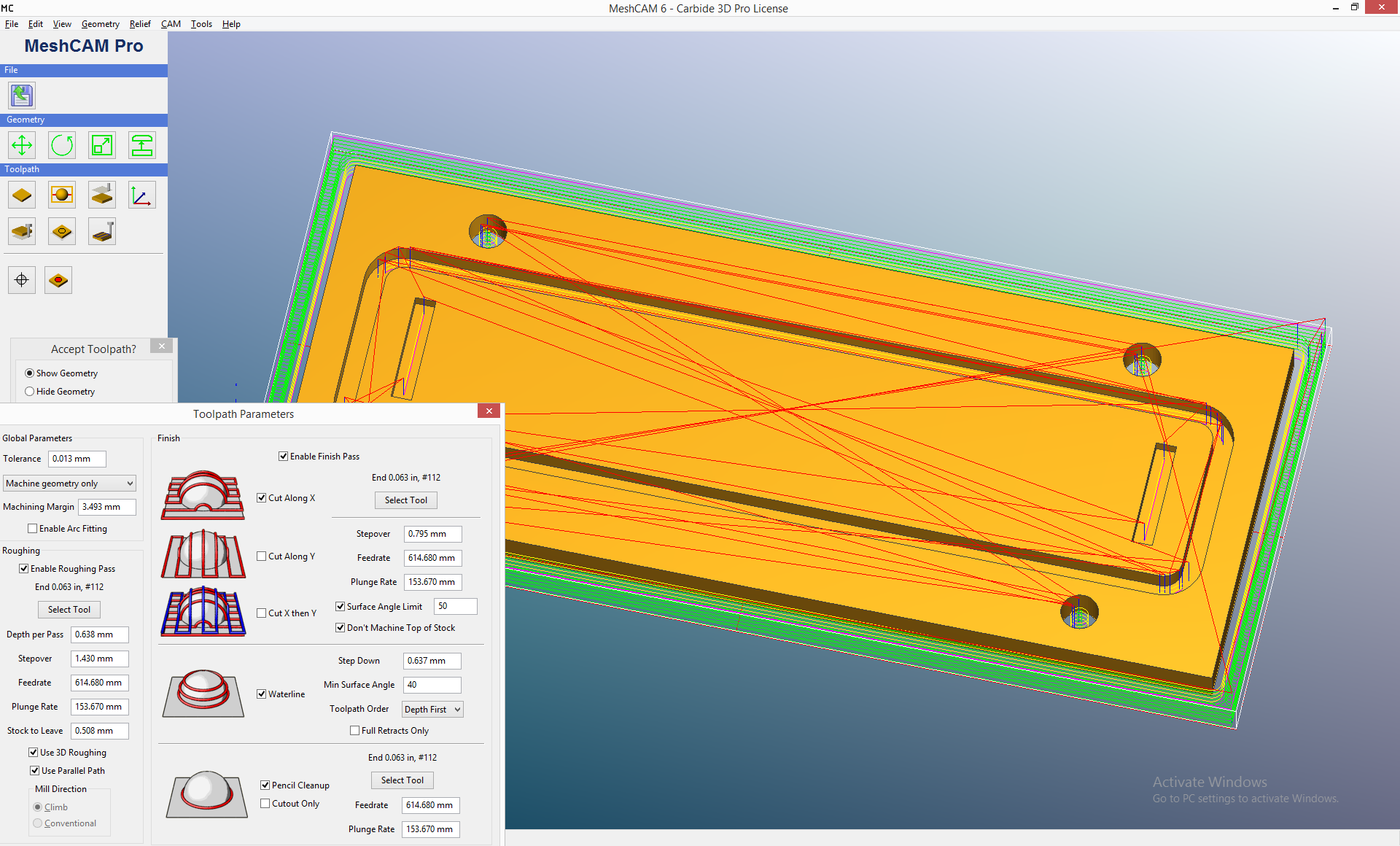
If I create an imaginary tool bit with 1.45 mm diameter and set ‘Stock to Leave’ = 0 then the toolpath shows the expected waterline circuits though the groove. However, I believe if I run this job using the 0.063" (1.55mm) tool the grooves will be 0.1mm wider than the drawing, is that correct?
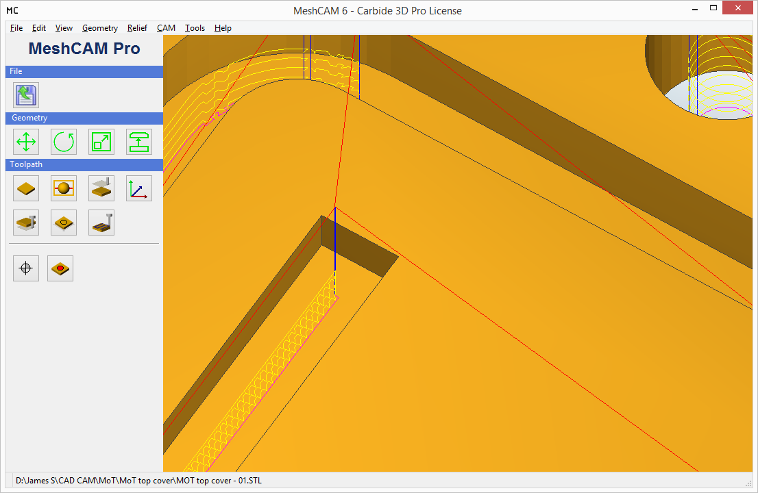
MeshCAM will honor the feature characteristics - when it can “feel them”. @Randy describes the process as a blind man with a stick (the tool) feeling around. The “feeling around” does the best it can however the math and logic used to do this have limitations. If the features is less than ~10% over the tool diameter the process doesn’t poke the stick into the feature - it’s doesn’t feel/see it.
Since I don’t have a toolbit smaller than the 0.063" tool, is there another way to create a toolpath that the 0.063" tool can cut?
There are two settings that affect the ~10% number. Since you’re “on the edge” these may help. These are things one should be doing anyway.
A) The MeshCAM tolerance setting should be 0.0001" (or the metric equivalent).
Give MeshCAM the ability to work the surface with the finest possible tolerances.
B) When your CAD package spits out the STL file, tell it to output as many triangles as it can.
Give MeshCAM as much data to work with as possible; the best possible approximation of the surface.
If you’ve got a computer with a 64-bit OS, 4 GB or more of memory, and 2 or more high speed cores, let MeshCAM crunch! The more time spent analyzing the STL file, the better the machining.
Or do I just have to wait until I can get a smaller tool?
Trying the above things (and use them from now on) and see what happens. If the setup is just too close to the edge of how MeshCAM works, you’ll need to go smaller.
MeshCAM will use a smaller tool to create a larger feature but applying the necessary operations.
mark