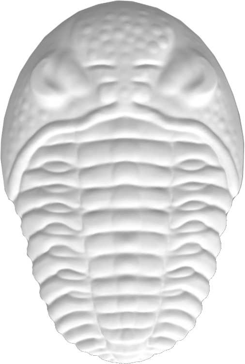
I’m starting a small challenge coin project with a fantasy/steampunk trilobite theme. I’ll be posting the progress as it happens…
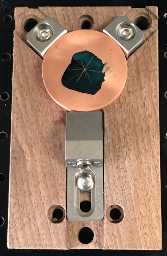
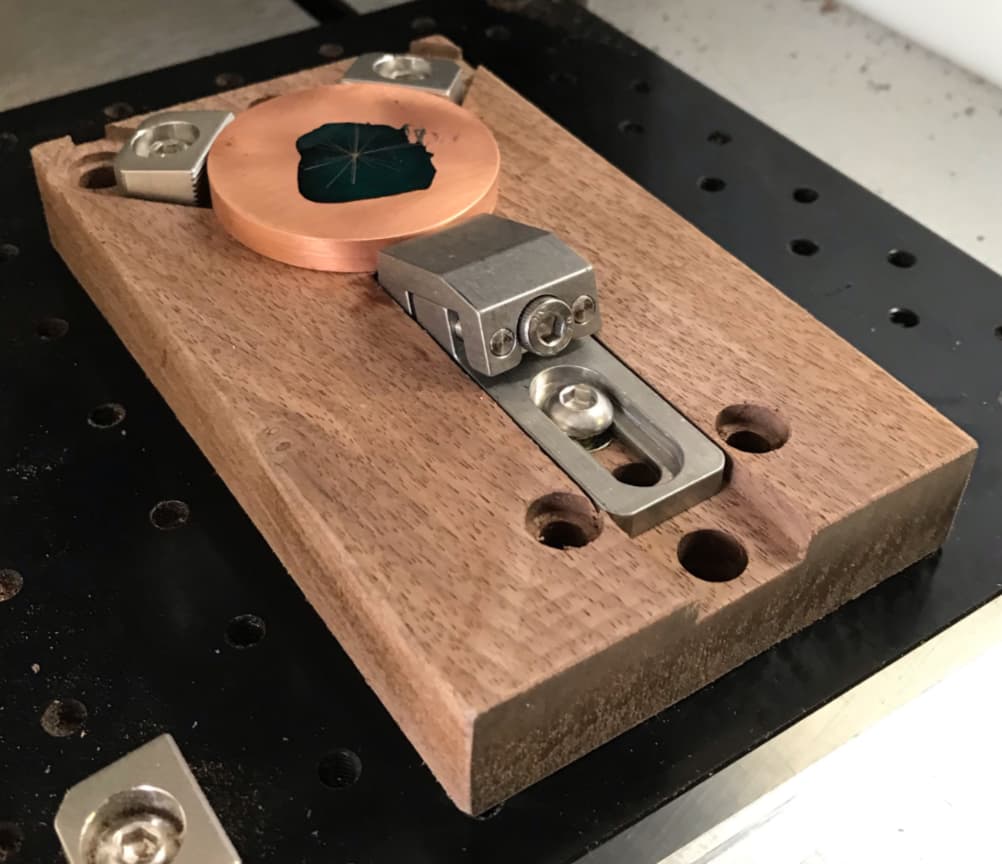
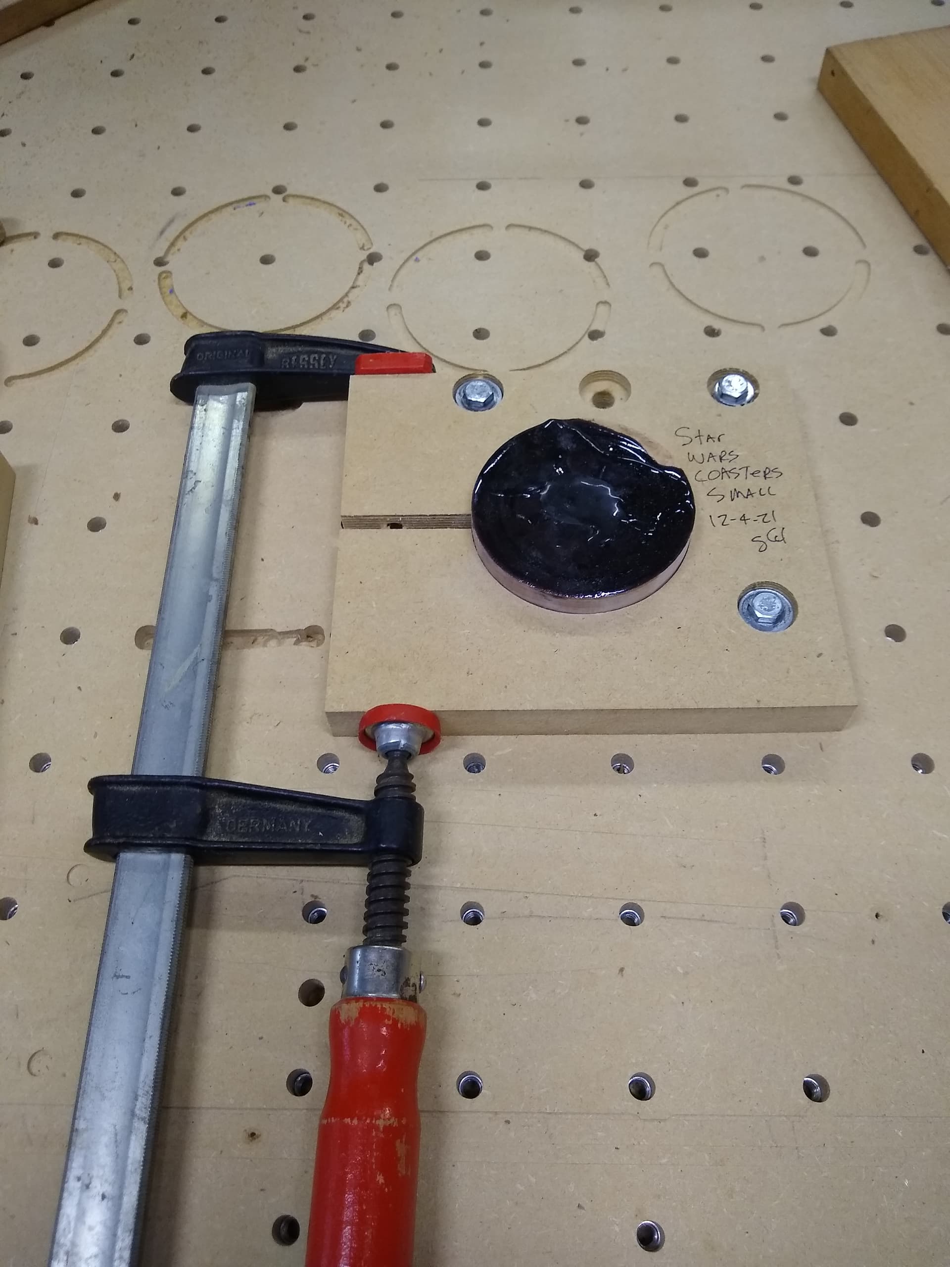
First, I need a better method of work holding than I’ve been using, so I’ll start by making an improved fixture to hold the roughly 2 inch diameter (48.3mm) by 1/4 inch thick (6.35mm) tellurium copper blank. I’ll be using tiger claw clamps/stops for the hardware, on a walnut base. It will screw directly to the threaded table rather than the compact vise and kludge I’ve been using. Since I do a lot of this kind of thing, it’s probably smart to make it adjustable…
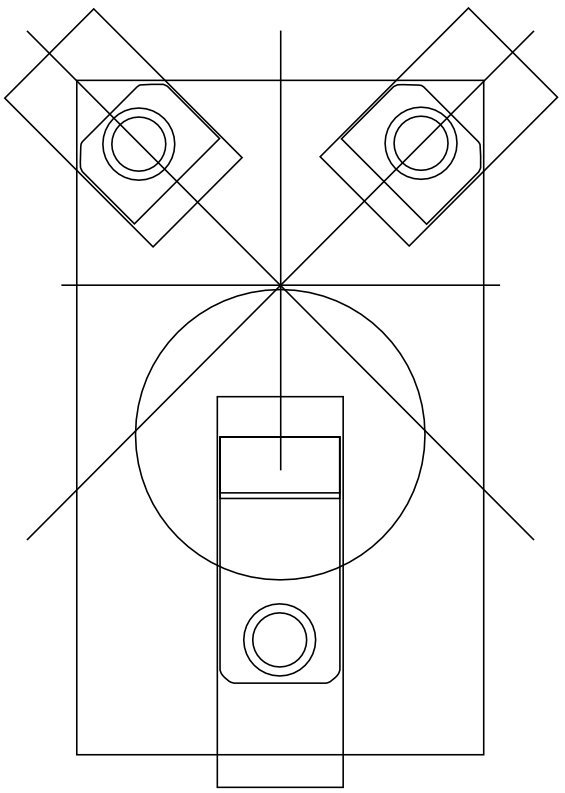
Here’s the basic design from my ancient coy of Carbide Create for my Nomad 883 Pro. I’ll be setting the near edge tops of the clamps below the surface of the 1/4 inch thick coin blank to reduce the chance of collisions with the clamp hardware.
In total, about 90 minutes machining the walnut, not counting having to rework the C3D file on the fly because I forgot to reduce the Plunge rate (to 100 mm/min) for the 1/4 inch square end mill, which intermittently stalls the motor at the published rate.
neat, I need to do something similar, a friend wants some branded poker tokens made, the dealer button and blind chip things (no idea their actual named) but he runs a little league and wanted some made out of brass
I am using this center finder for locating center on the coins I make. I prefer using the center of the coin instead of the edge because I do a final trim along the outer edge to clean up any off-centered-ness I have. With a round item, it is VERY easy to see the difference in rim thickness if it is even the slightest bit off. I do not use this type of clamping system though. I do the blue tape - superglue method so I can do that last trim path around the outside of the coin.
I use a 1/8Inch diameter tapered point to set the zeroes. Most of my projects are art projects, and I’m really only interested in the top surfaces rather than true Z dimensions, so I find it easier to set zeroes using top center. Plus, there aren’t any corners on a circle!-)
PS I turned this blank on the lathe to save time…the CNC run times for these parts are bad enough already. I use a height gauge and granite surface plate to determine the centers…been working out so far, knock on wood.
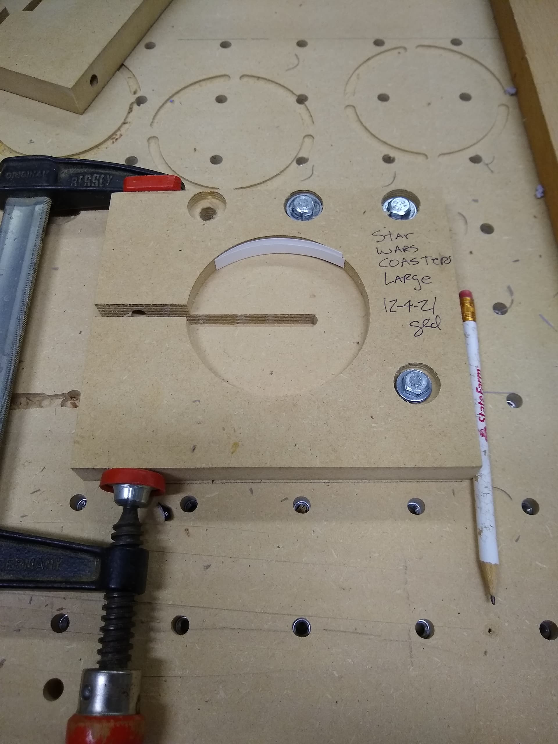
I made a couple of holding jigs for surfacing epoxy filled wood coasters. I have a 2 inch Tee nut spoil board so I made the right hand holes so a 1/4-20 bolt would hold them down and the other two holes oversized so when I tightened down to hold the coasters so I could tighten them up after capturing them in the jig. I have used this type of set up to hold round objects a few times and it works well. Once I set the X and Y center in the center of the jig I just put in the 12 coasters and reran the gcode over and over. I used the top surface as Z zero and used a fly bit that was set to take 0.010" per pass and made the pocket 0.010" so a single pass was made. All my blanks were the same thickness so I could just rinse and repeat over and over. I drilled a hole on the left side through for a bolt and a brass insert but did not have a bolt long enough so I just used a clamp. You could do something similar for your coin and the center can be used over and over as well as the Z height.
Additionally if machining only one side of the coin you could use the painters tape and super glue to secure the coin to the spoil board.
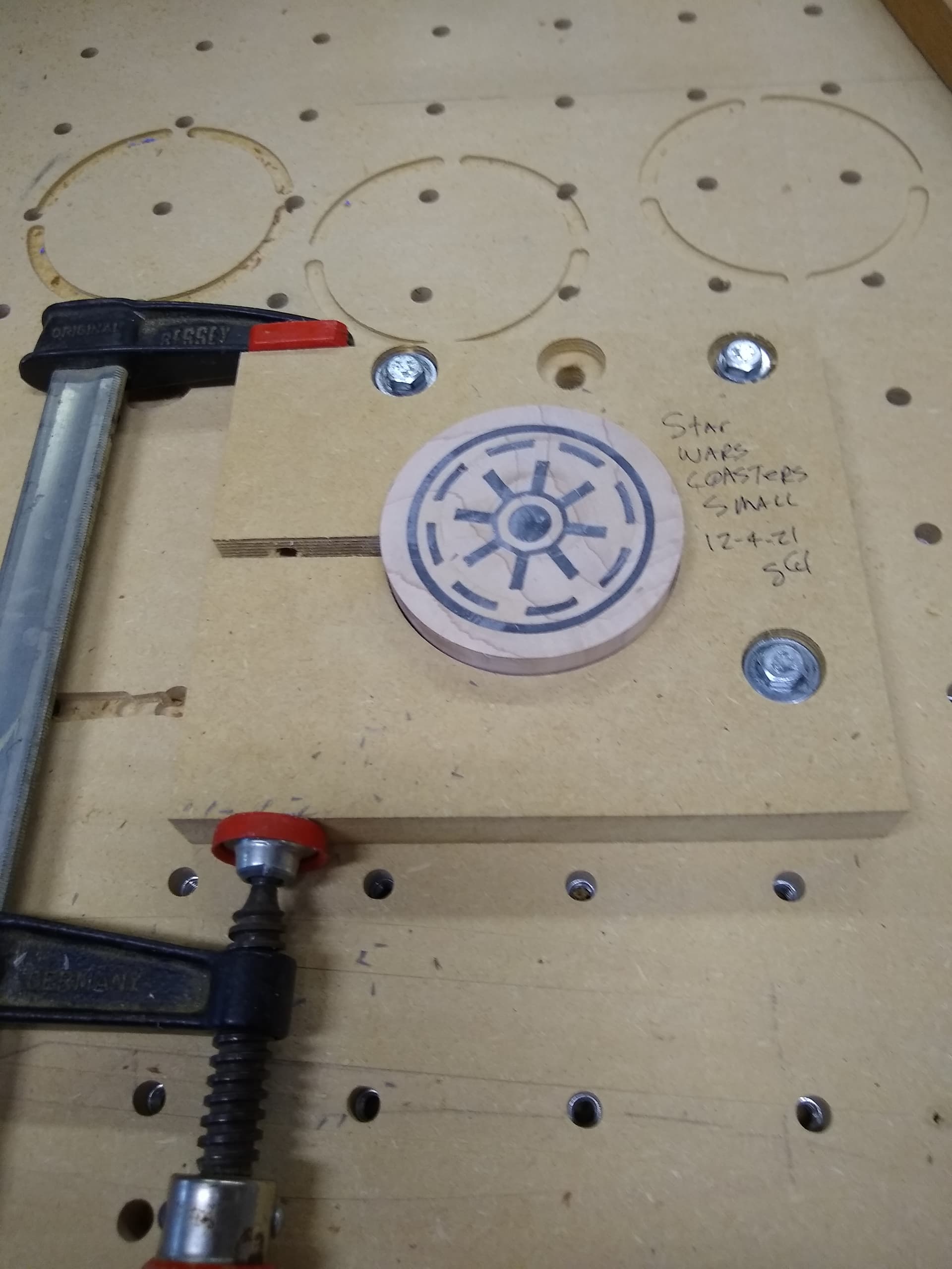
I just used a piece of mdf large enough to get my 2 inch spacing hold down bolts. I created the center pocket for holding the coasters in this case 3/8" deep for my 3/4" coasters. I cut the larger washer pockets .80" and the through bolt holes at .26" and .35" and a .26" slip cut from top to bottom of material to give me the means to squeeze the round coasters so they did not move. I was able to use a #201 for the whole jig. Additionally I unchecked my BitSetter so I would not waste time checking the same bit over and over. After each coaster the machine would return to the rear center and would just run again after unclamping the machined part and reclamping the new part.
I cut the through grove first, then the .80 pockets .25" deep and then the two different through holes for the bolts and the coaster pocket last. I made some test circles slightly under sized in the mdf with pockets and then drew a circle slightly larger and did a contour inside cut to slightly enlarge the coaster pocket until the coaster just fit.
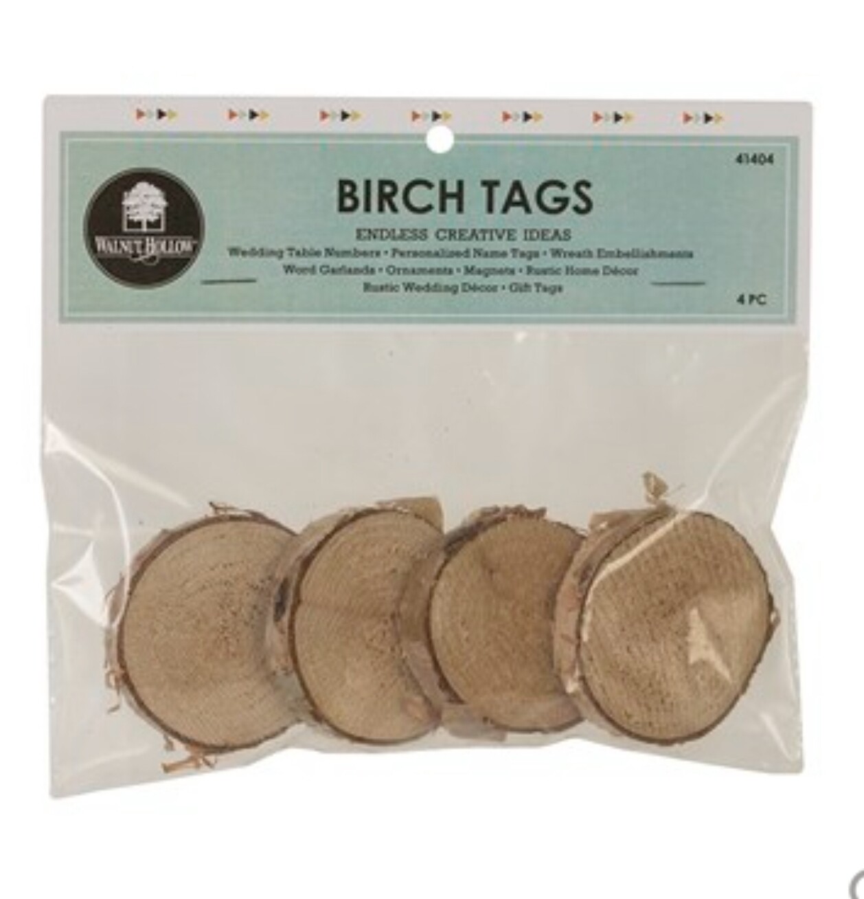
Thank you so much for the photos of your fixture. I have these birch rounds I want to cut and I’ve been thinking about how to hold them down. Because they aren’t uniform in size, I think I will use a similar fixture with two clamps, one on each side.
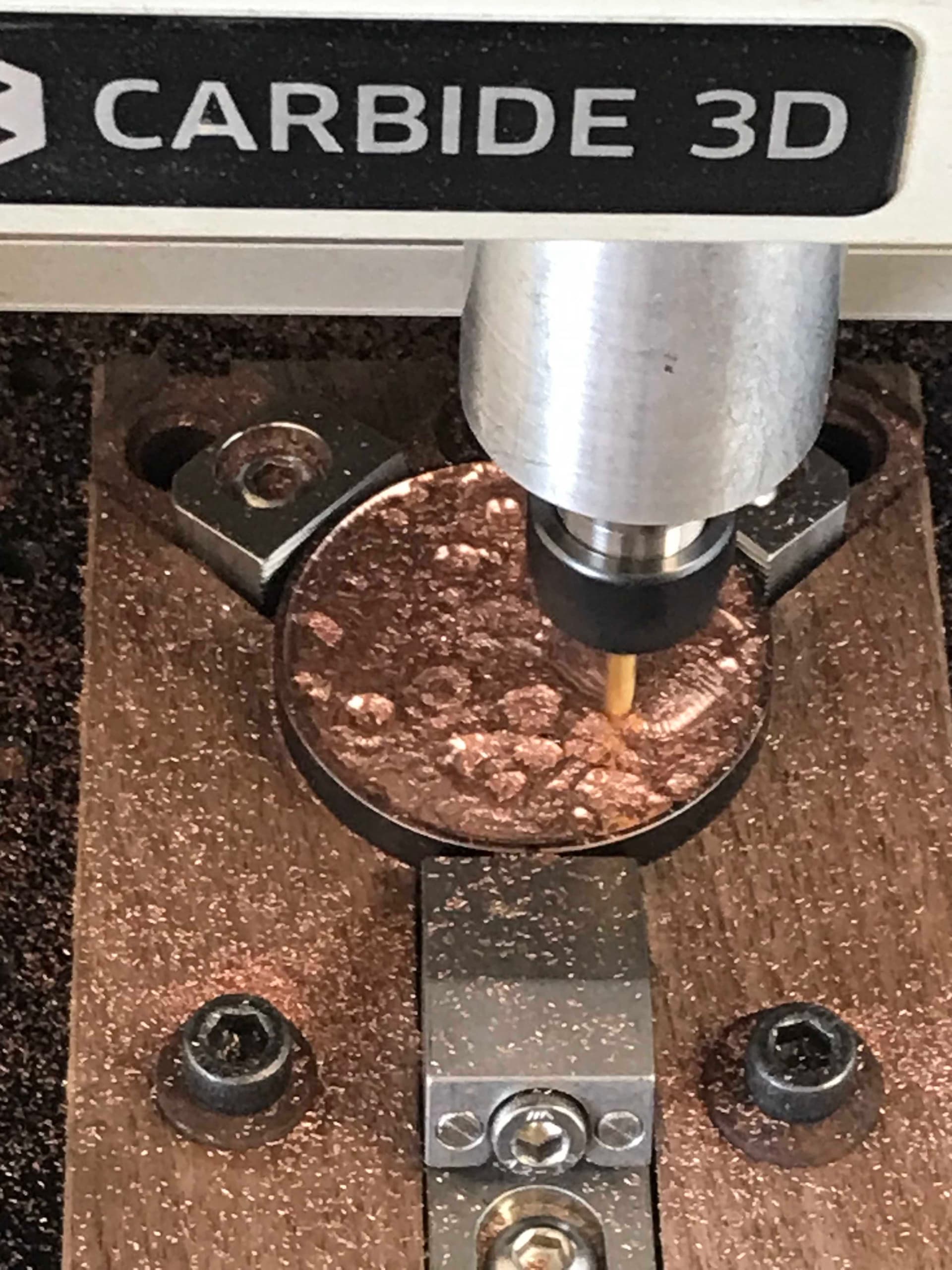
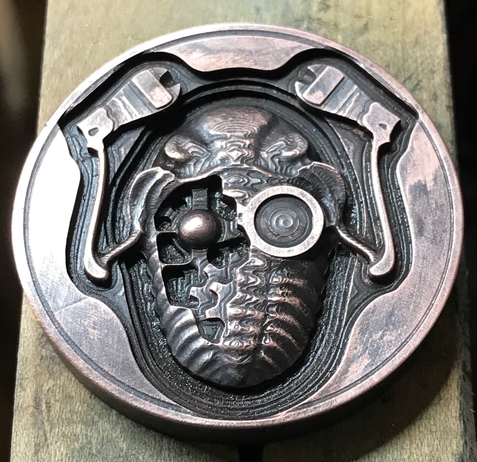
Mill away anything that doesn’t look like the model (2 inch diameter, 1/4 inch thick tellurium copper). 1/8" ball end mill, 1/16" ball end mill and 1/16" square end mill (in that order), about a 2 hour run time on my Nomad 883 Pro.
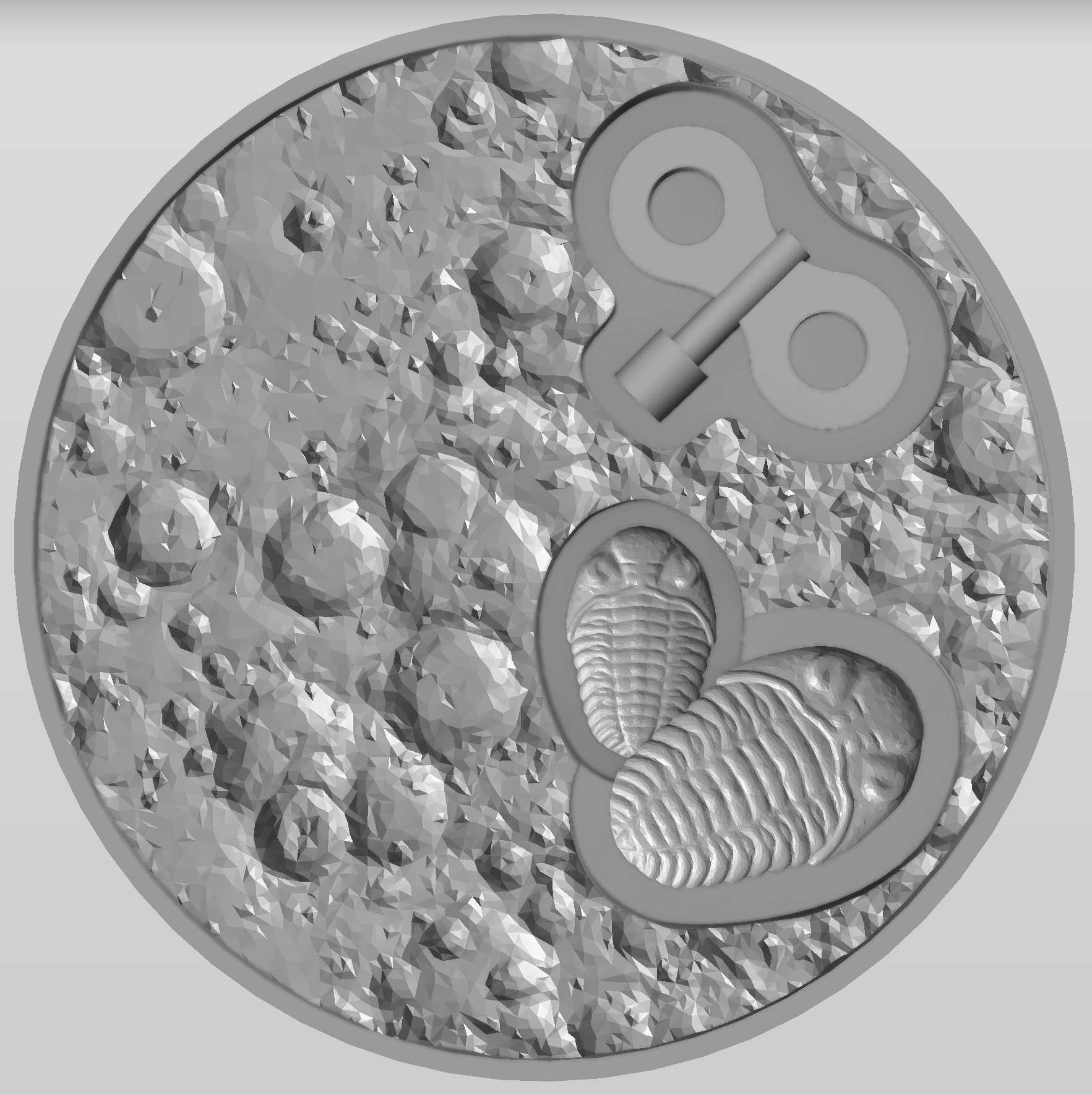
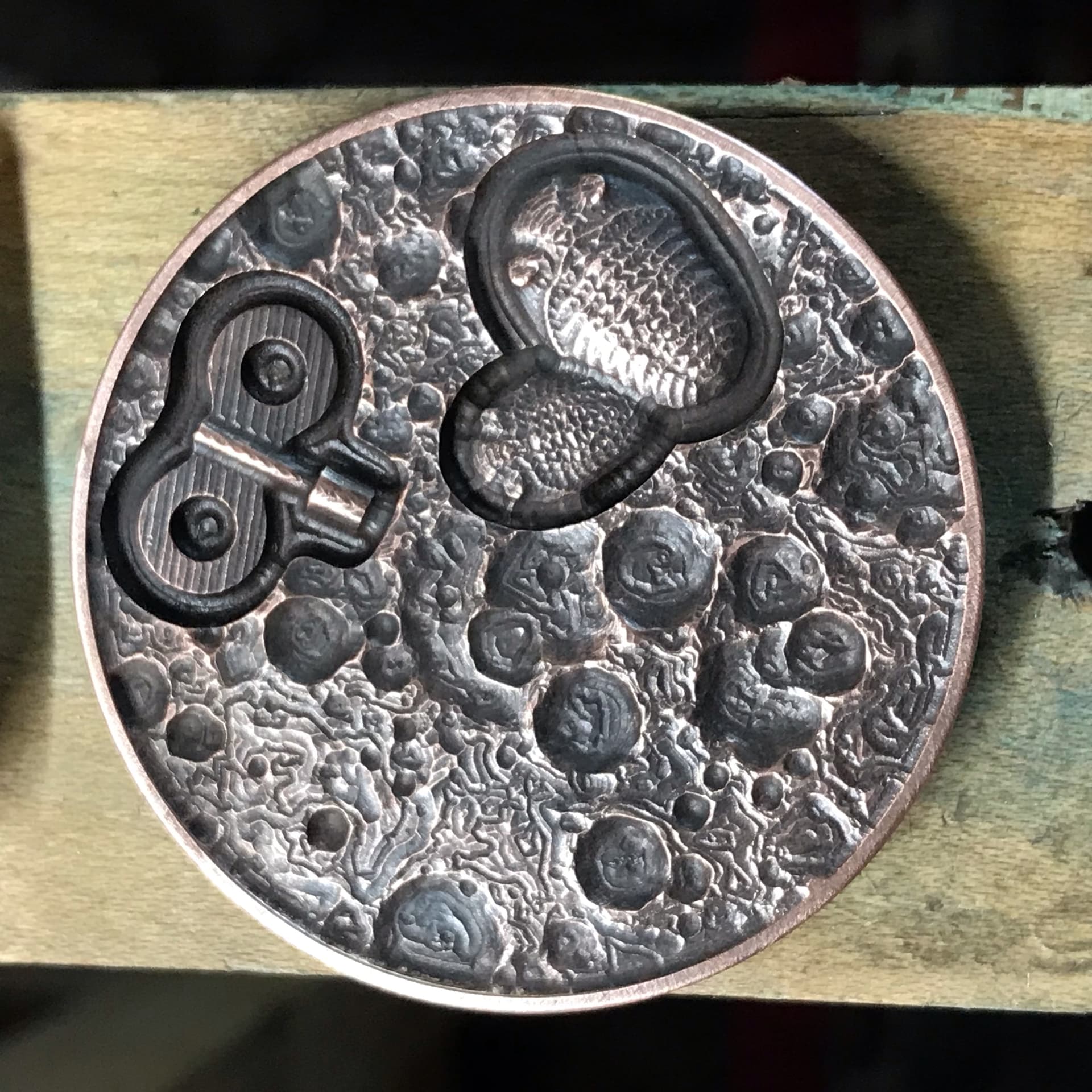
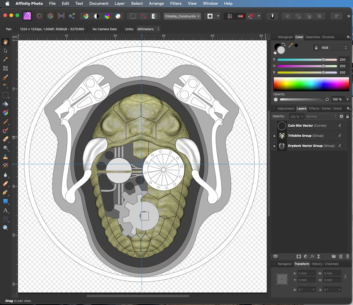
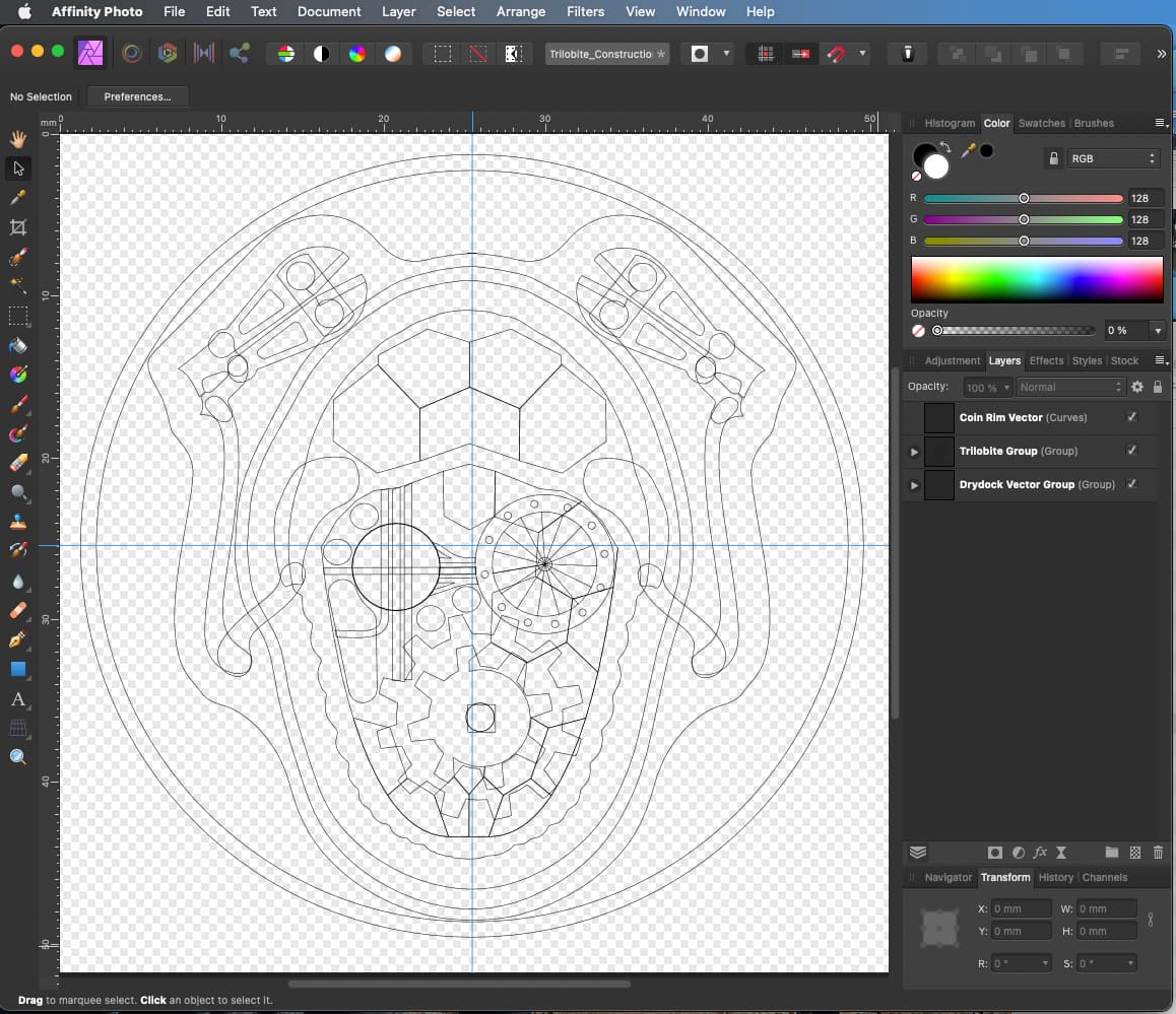
Here’s the front side of the “trilobot.” Using a screenshot of the 3D trilobite from Fusion360, I used Affinity Photo to design the added bits, transforming my rough sketches into vector format.
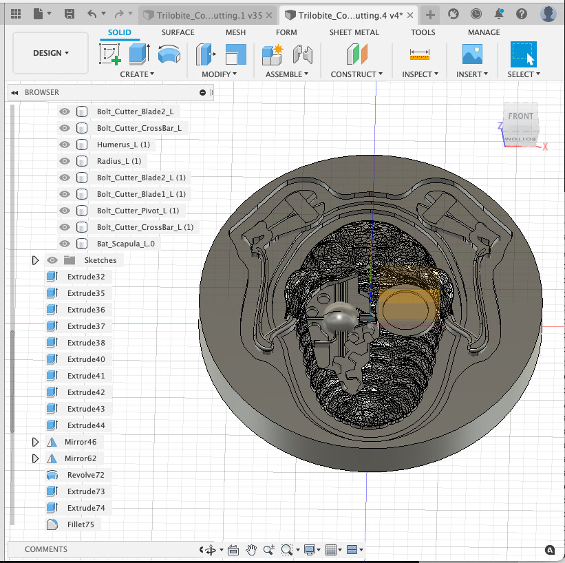
Using Fusion360’s CAM features, I created the toolpaths for milling. The biggest secret in making something like this work is to scale and separate the bodies so as to be successfully milled by the smallest end mills, in the case 1/16 inch diameter ball and square end mills.