Aluminium Spur and Pinion Gear
I just wanted to share the project that I submitted for the community challenge with the topic being ‘gears’. I really enjoyed the challenge of machining some small and functional RC gears out of aluminium with all the correct geometry. Apologies for some of the late replies, this project has taken up a lot of time over the last few weeks.
A few days after seeing the community challenge with the topic being ‘gears’ I decided to see if it was possible to machine an RC car aluminium spur and pinion gear. I’m studying mechanical engineering at university and have some experience with gear design. I will go into more detail below about the gear design, but everything was designed from scratch in Fusion 360 without the use of a gear generator.
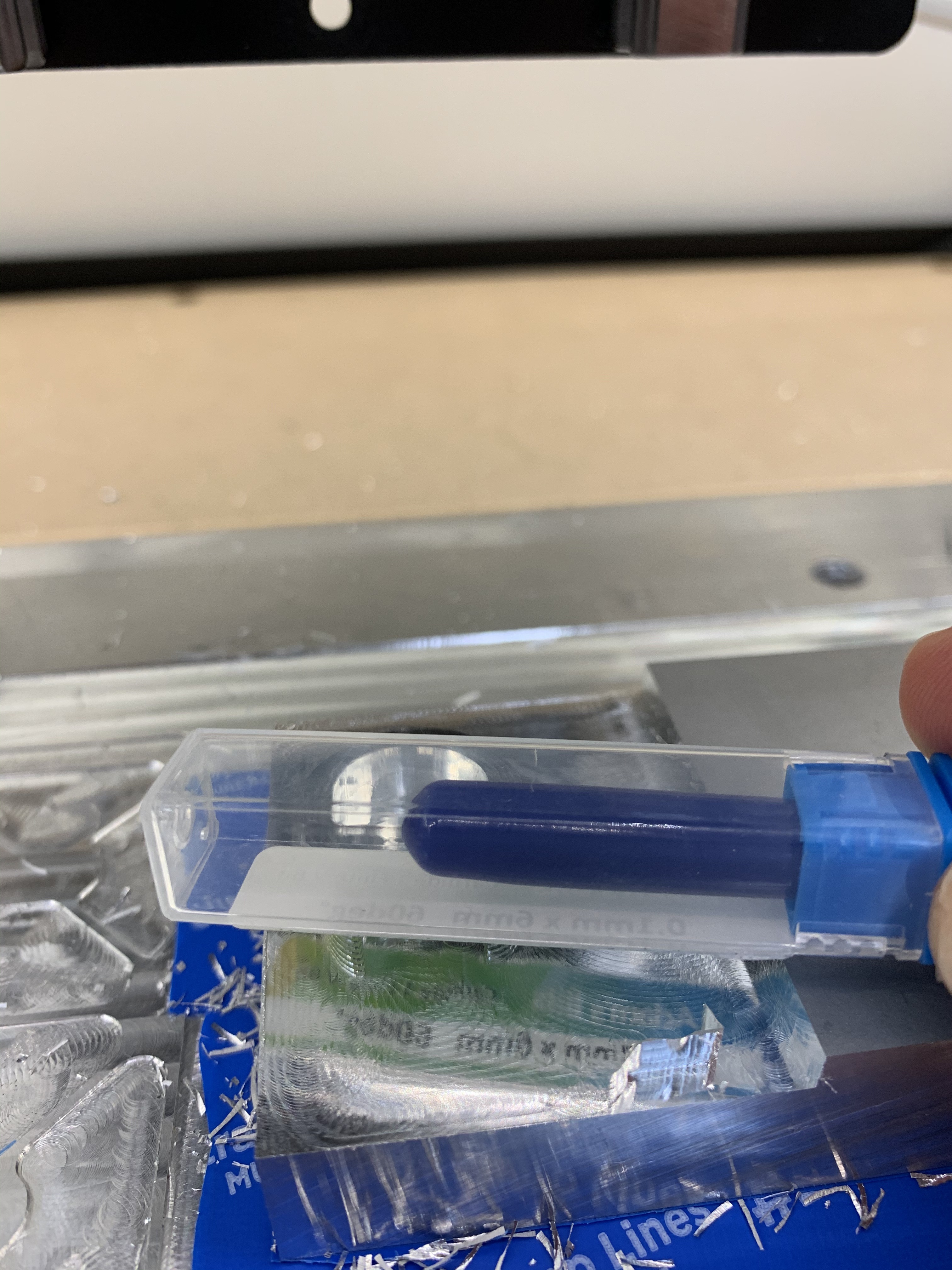
The most challenging aspect of this project was the tolerances required for the gears. For the spur gear the bore for the drive shaft and bearing had to be a perfect fit so that the whole differential assembly would spin smoothly at high RPM. Another challenging aspect was the endmill required to mill the tooth profile, as the spur gear used a MOD 1 gear profile I needed to use a 1mm endmill to mill the profile.
Gear Design:
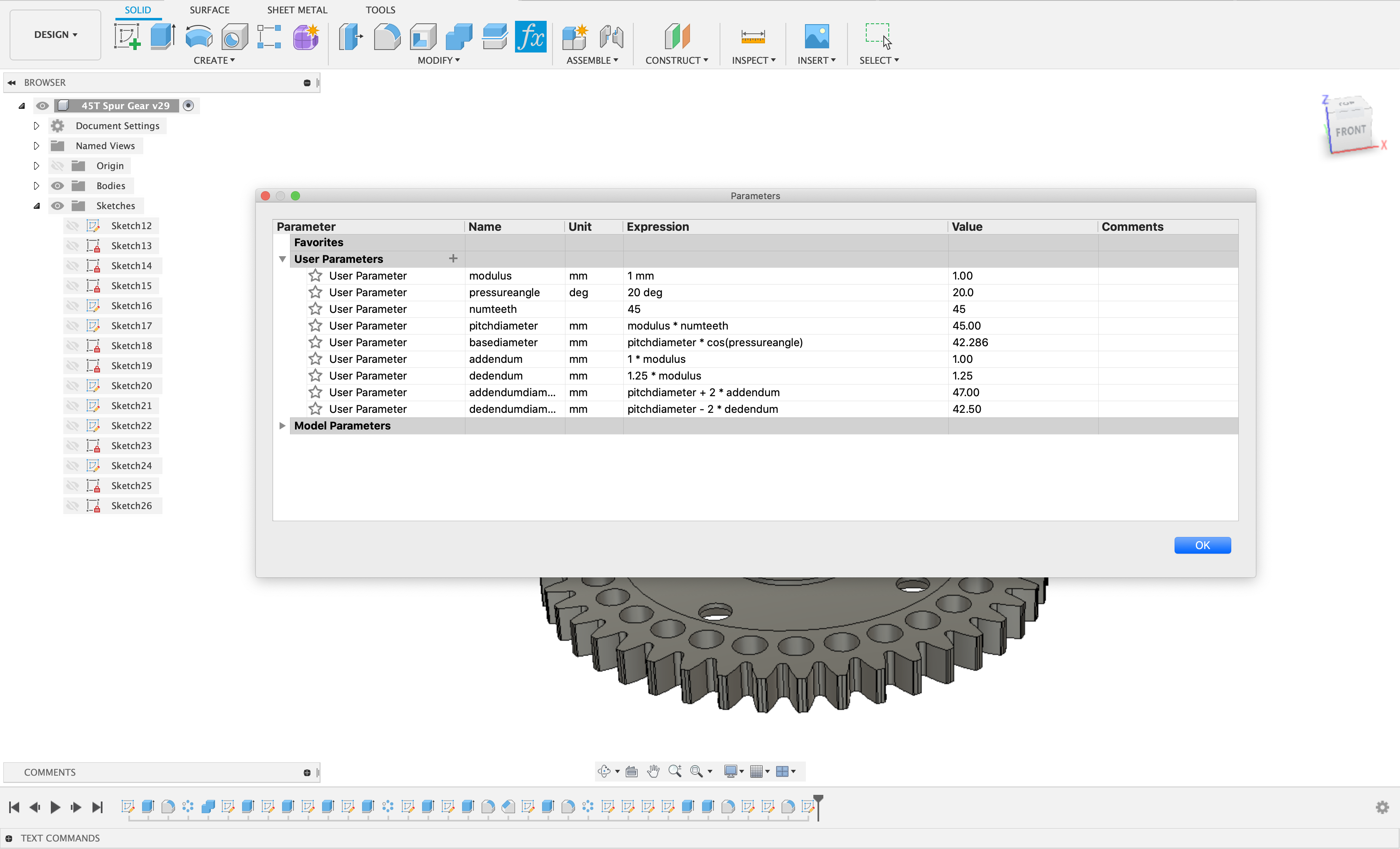
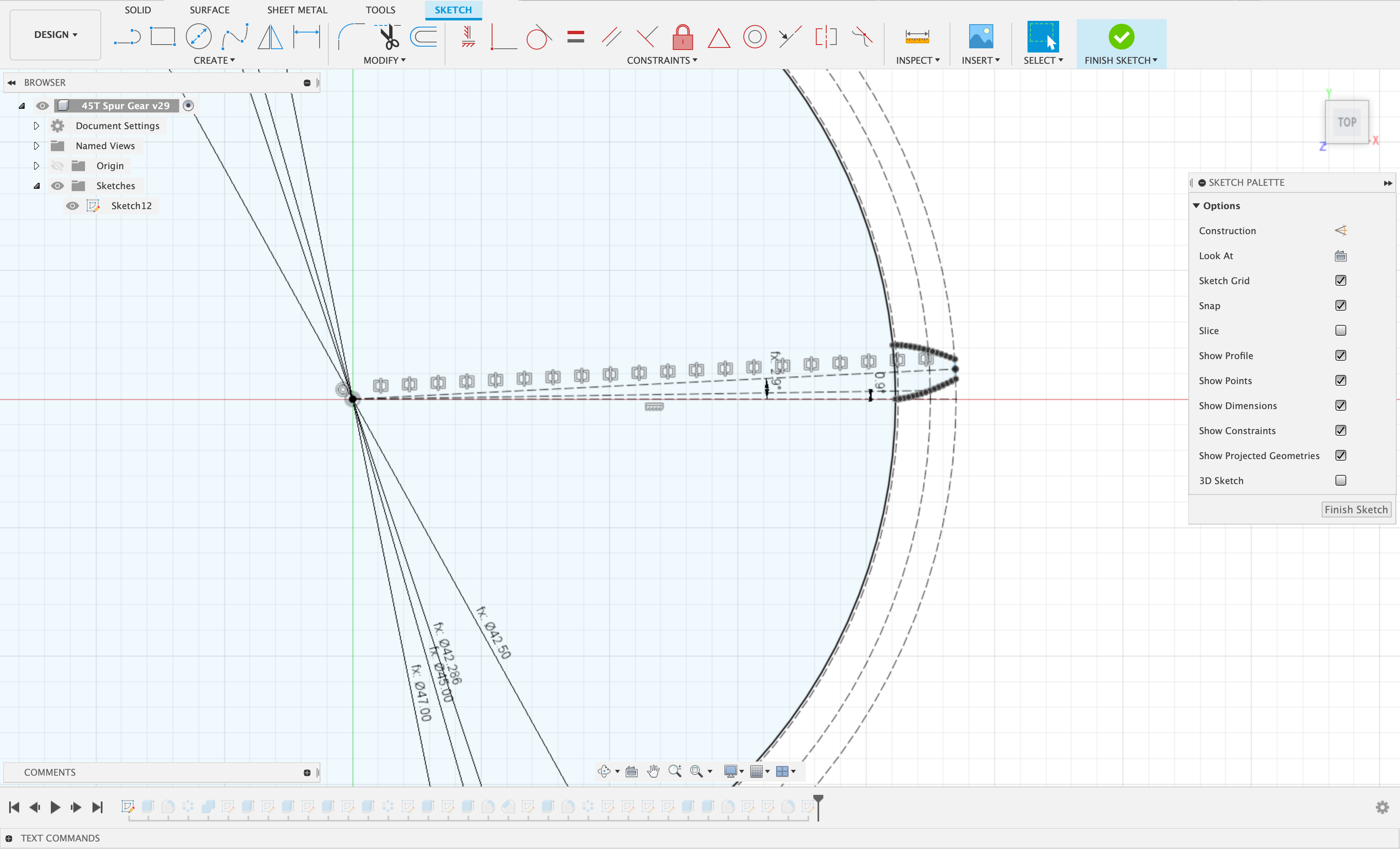
For the design of these gears I started with some simple gear calculations to work out basic parameters such as, pitch diameter, base diameter, addendum, dedendum, modulus and the pressure angle. From here I moved to Fusion 360 and put these equations into the parameters box so that the sketch was parametric.
The gears had a modulus of 1 and used an involute tooth profile. To get the correct profile for the involute tooth profile I used a spreadsheet (This was sourced online) that generated a number of points along the spline curve. These points were then imported into Fusion 360 using the ImportSplineCSV function. Then from here I had the correct profile of the gear and could model all the other essential features required for both gears.
Image of the parameters used for the sketch.
Image of the sketched involute tooth profile.
CAM and Machining:
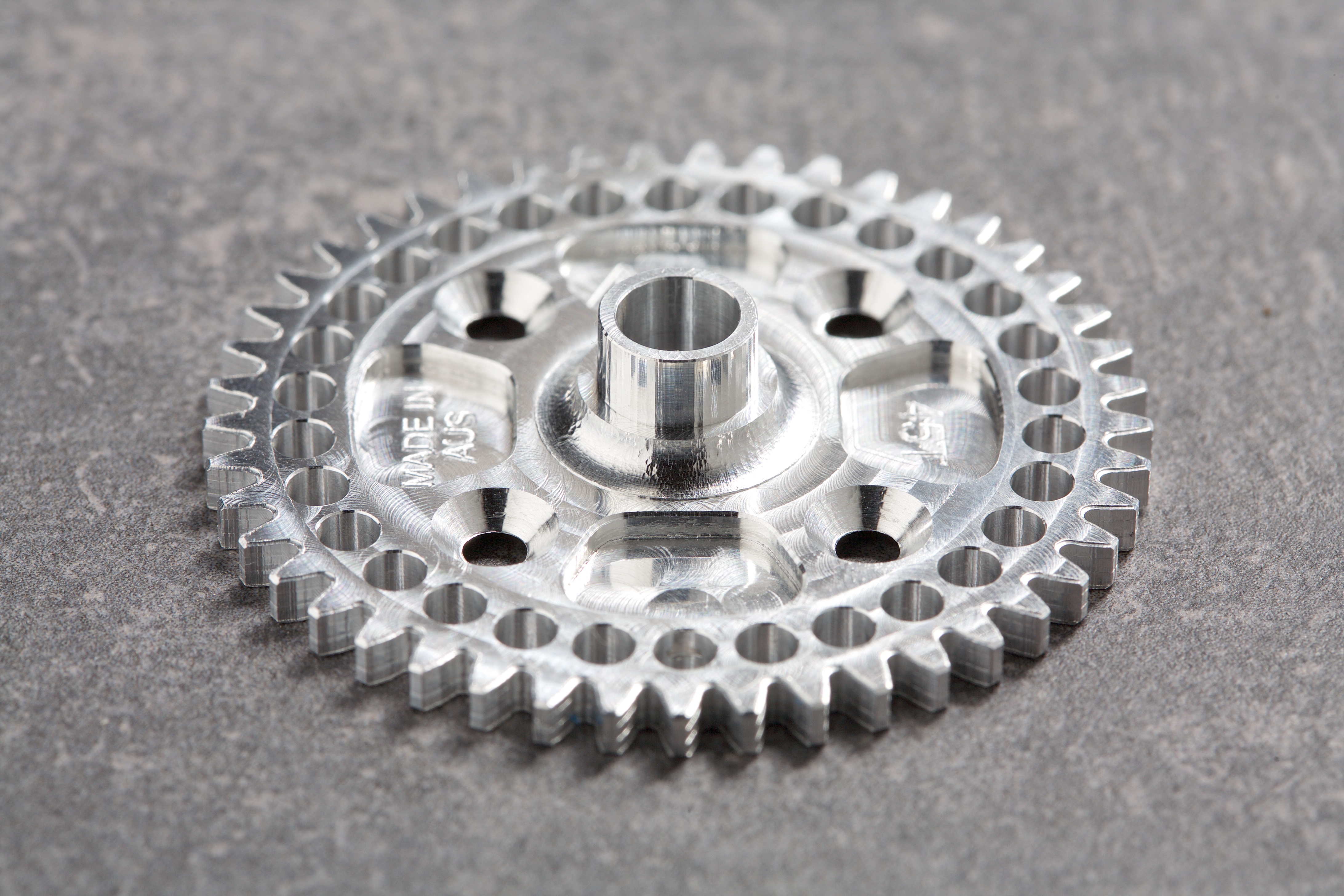
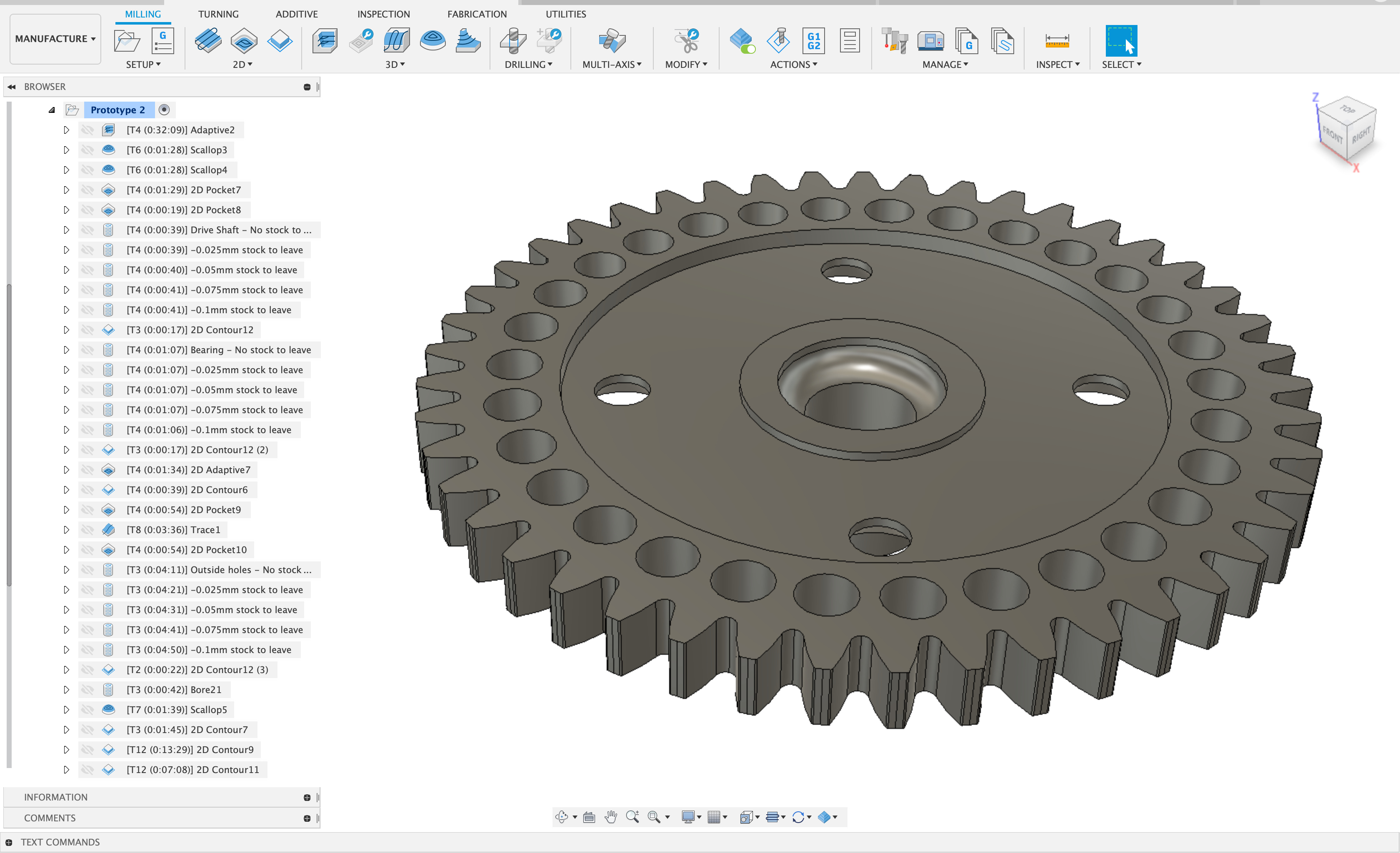
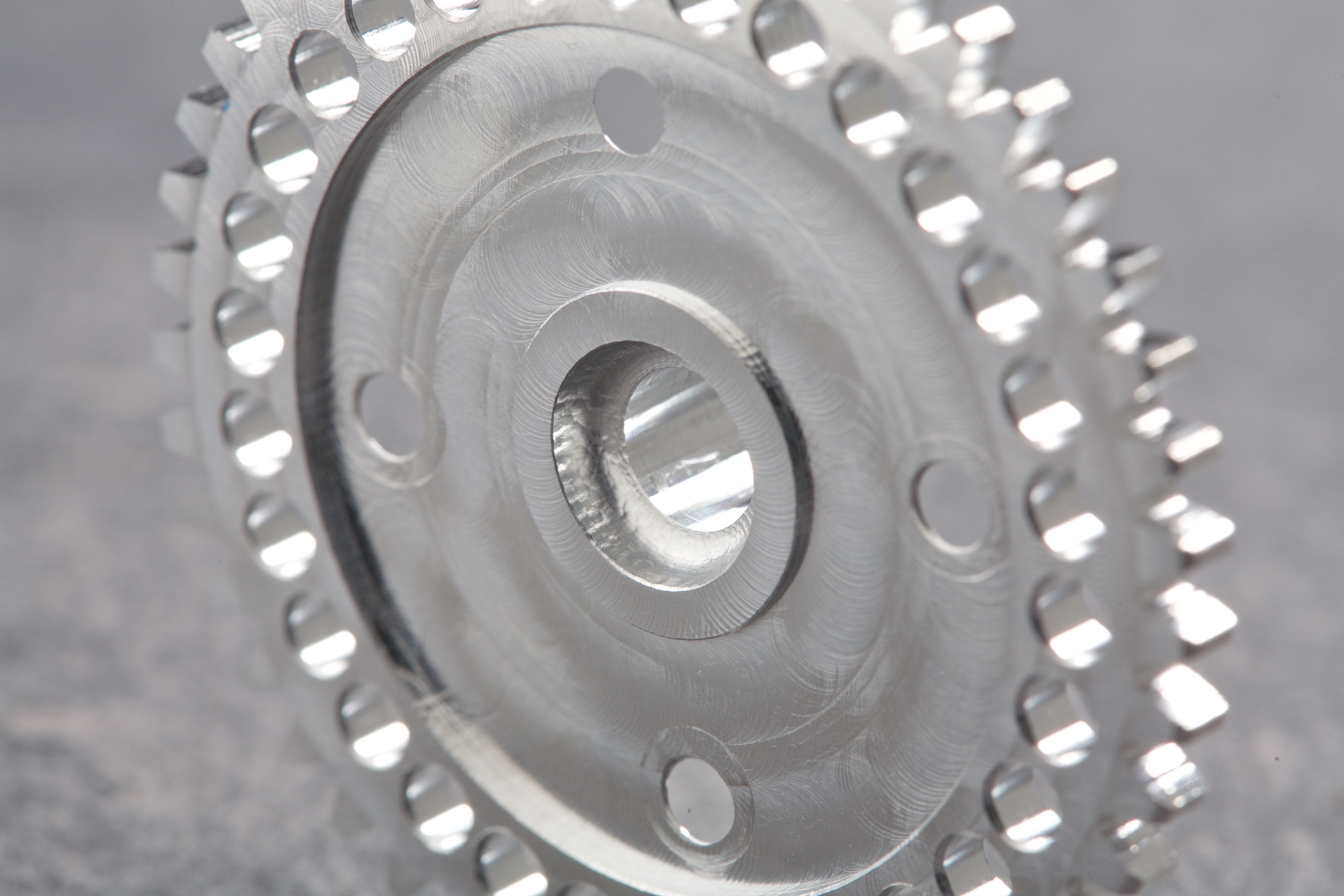
I spent a lot of time dialling in the CAM for this project and machined a number of different prototypes using different CAM strategies. For the final part I was able to get the tolerances perfect with zero play in the bearing and drive shaft fitment. The spur gear has lots of different features such as a filleted o-ring groove, 3mm holes around the outside to reduce the rotating mass and other pockets to further reduce the mass of the gear.
Both gears were machined using 6061-T6 aluminium and around 100 different tool paths for both gears. Each gear required two different operations for two sided machining and also some simple fixtures to secure and locate each gear for the second machining operation. I tried two different fixturing techniques for both gears until I was happy with the results.
An image showing some of the tool paths for the first operation of the spur gear.
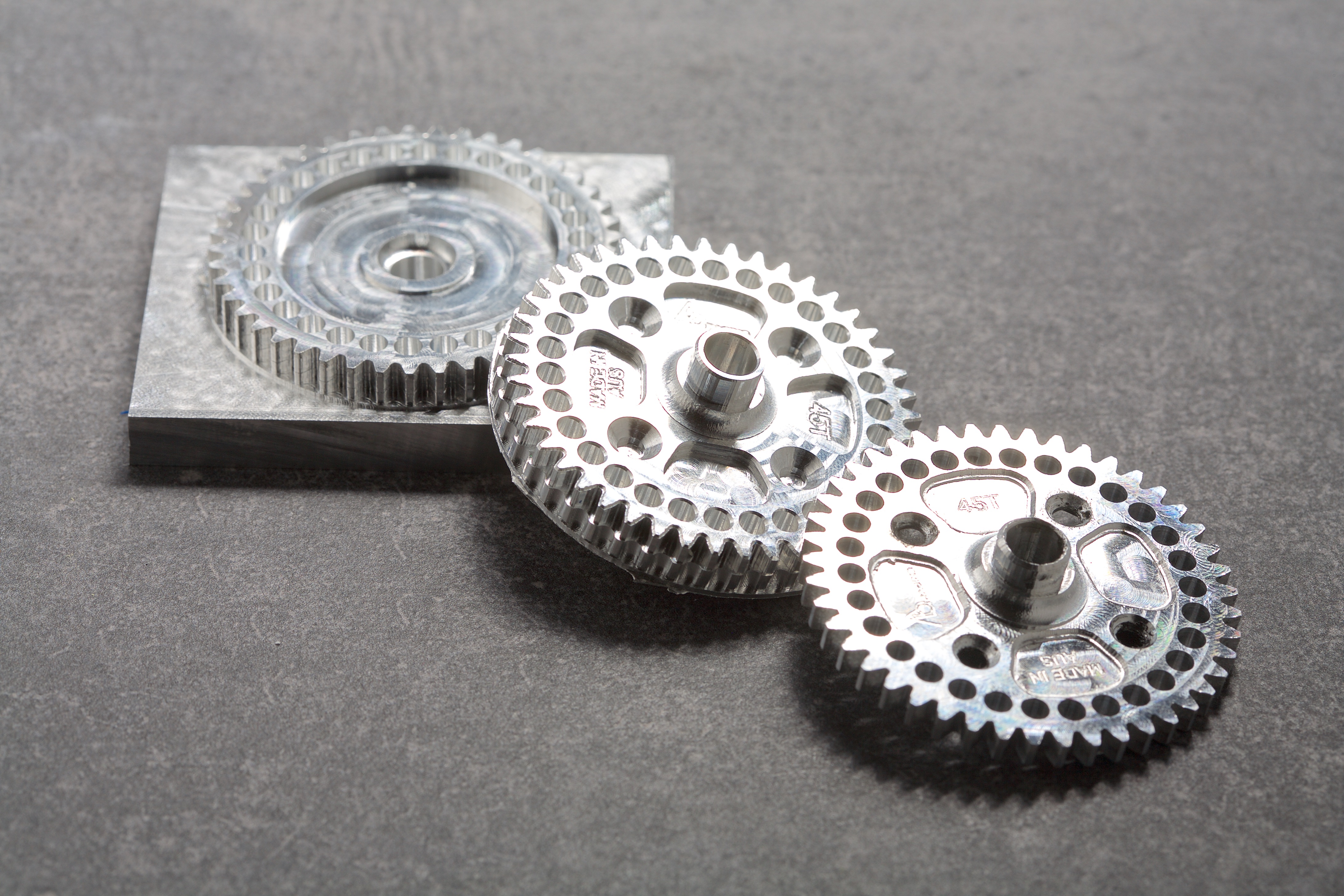
Overall I’m really happy with how this project turned out and it was one of the most challenging aluminium projects I have undertaken. Below are some images of the finished parts.
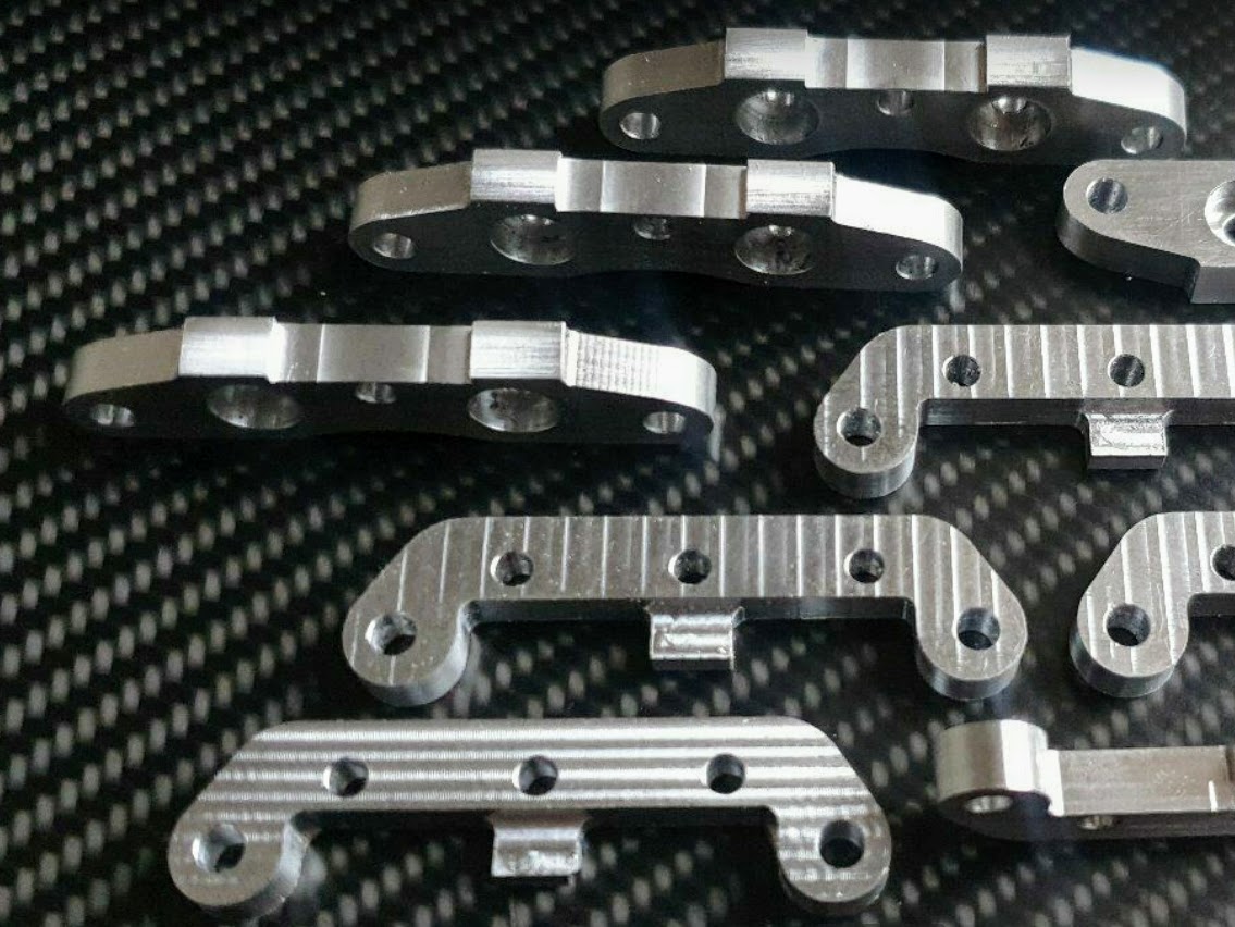
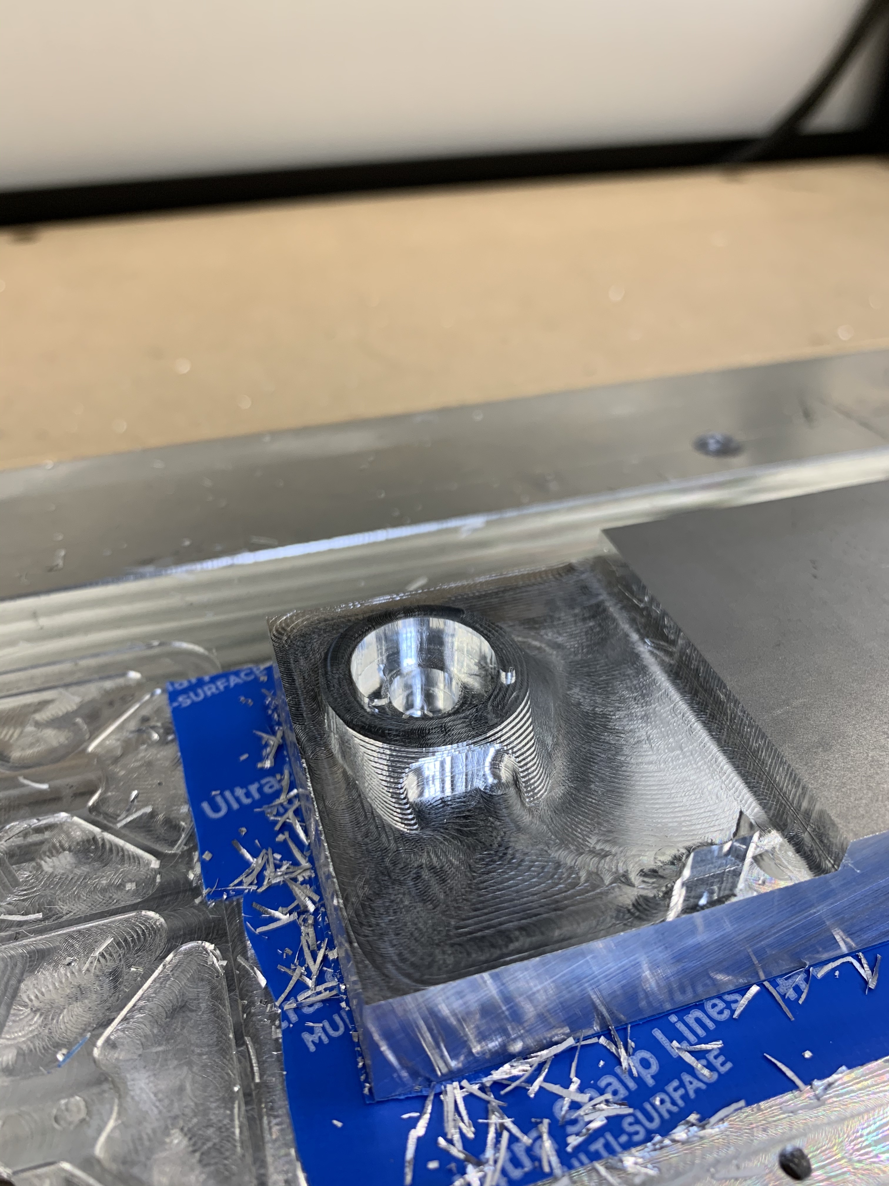
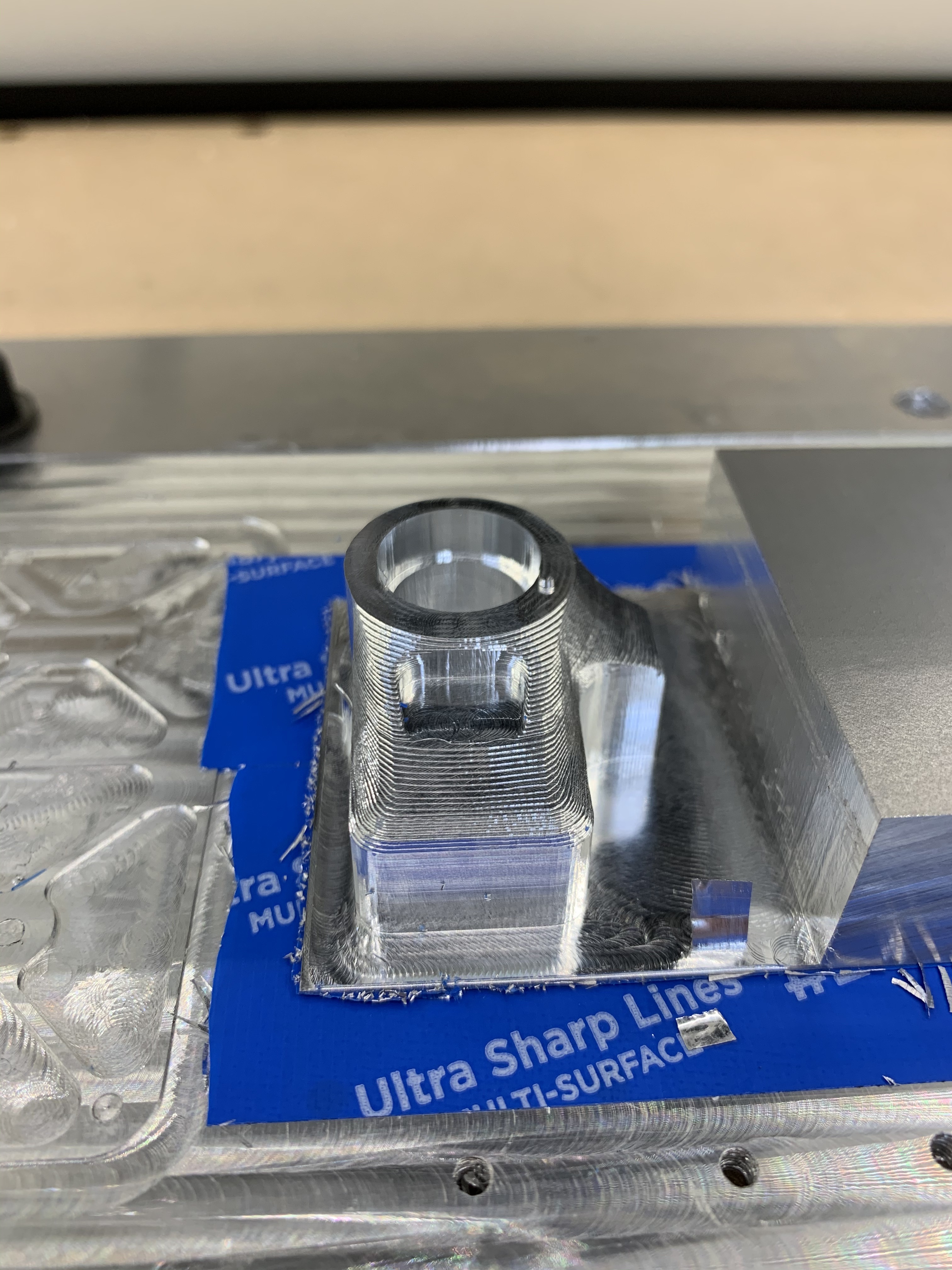
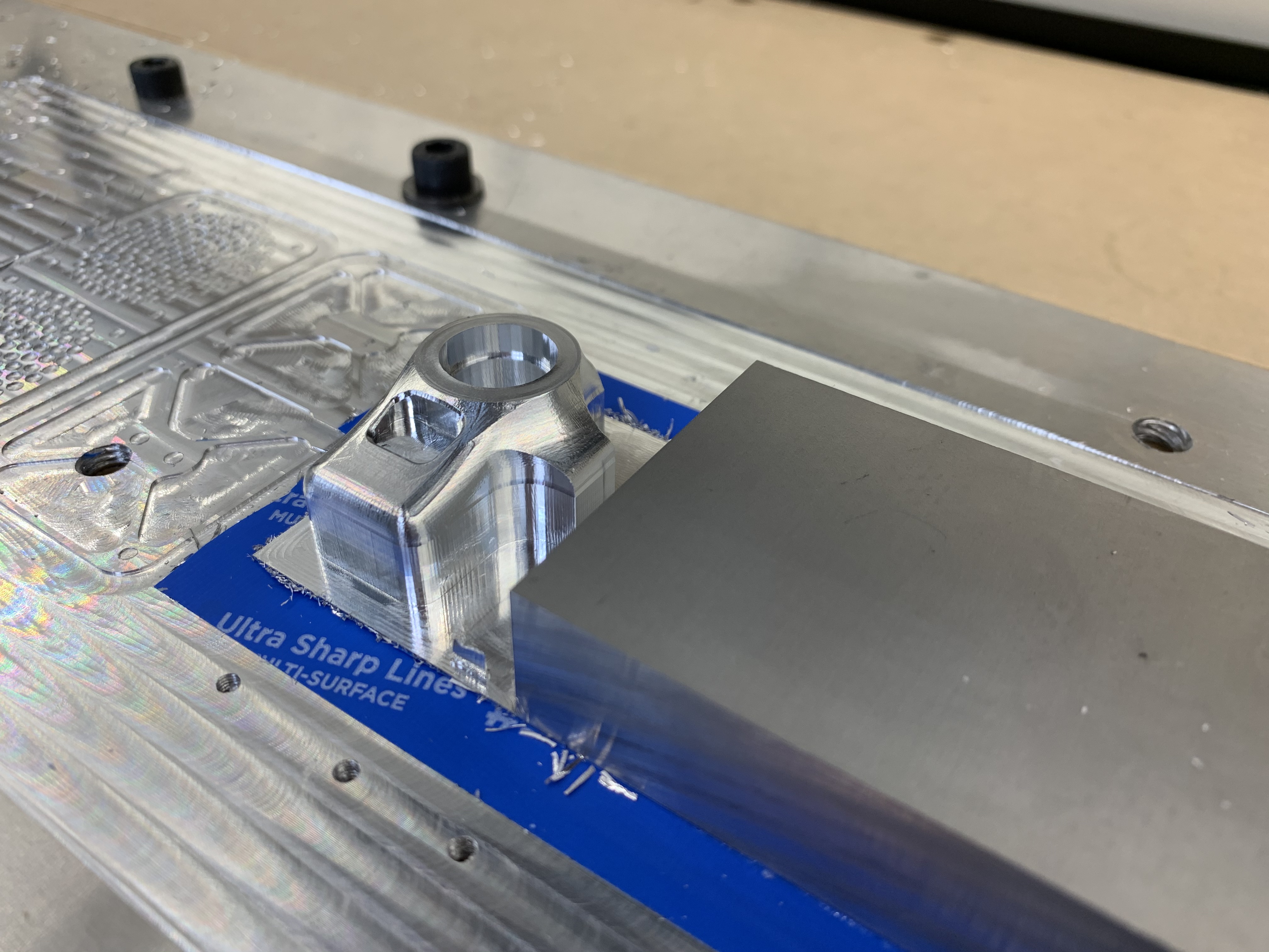
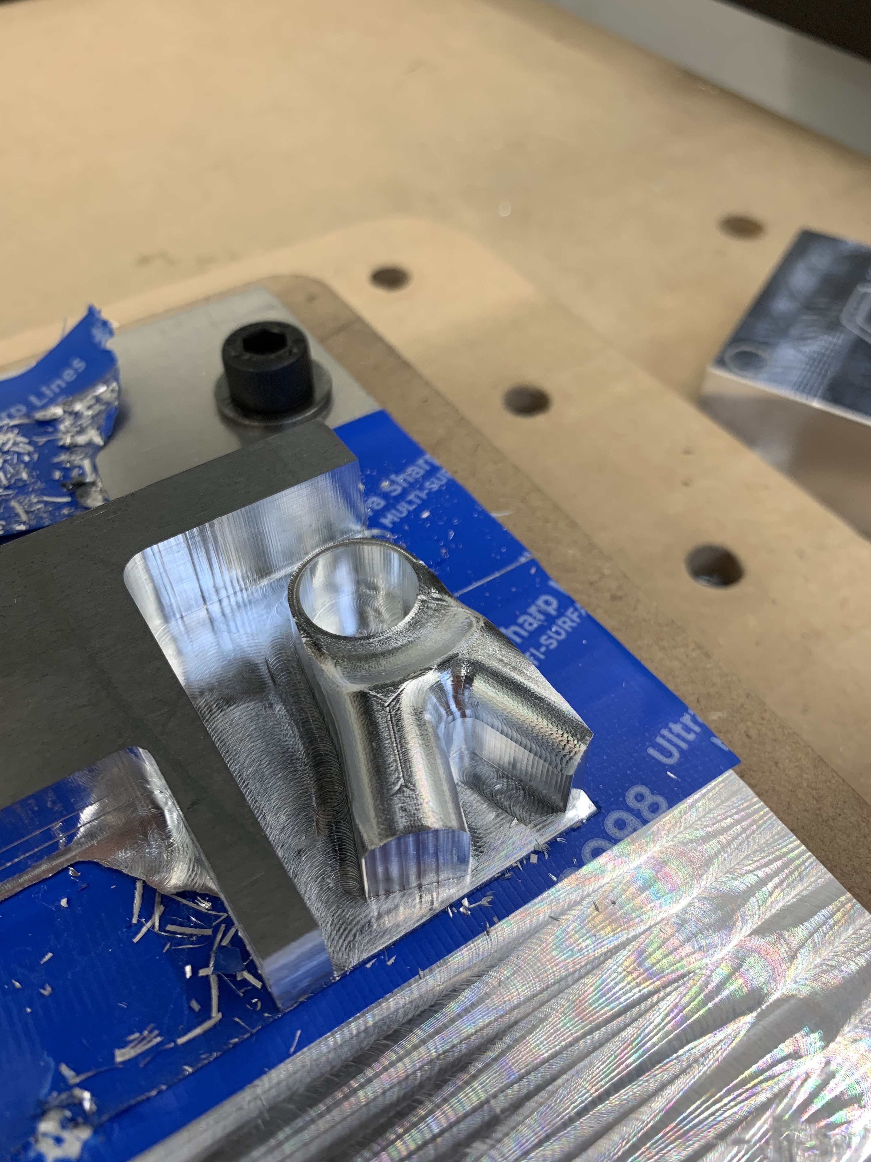
There were a number of different prototypes machined before reaching the final iteration.
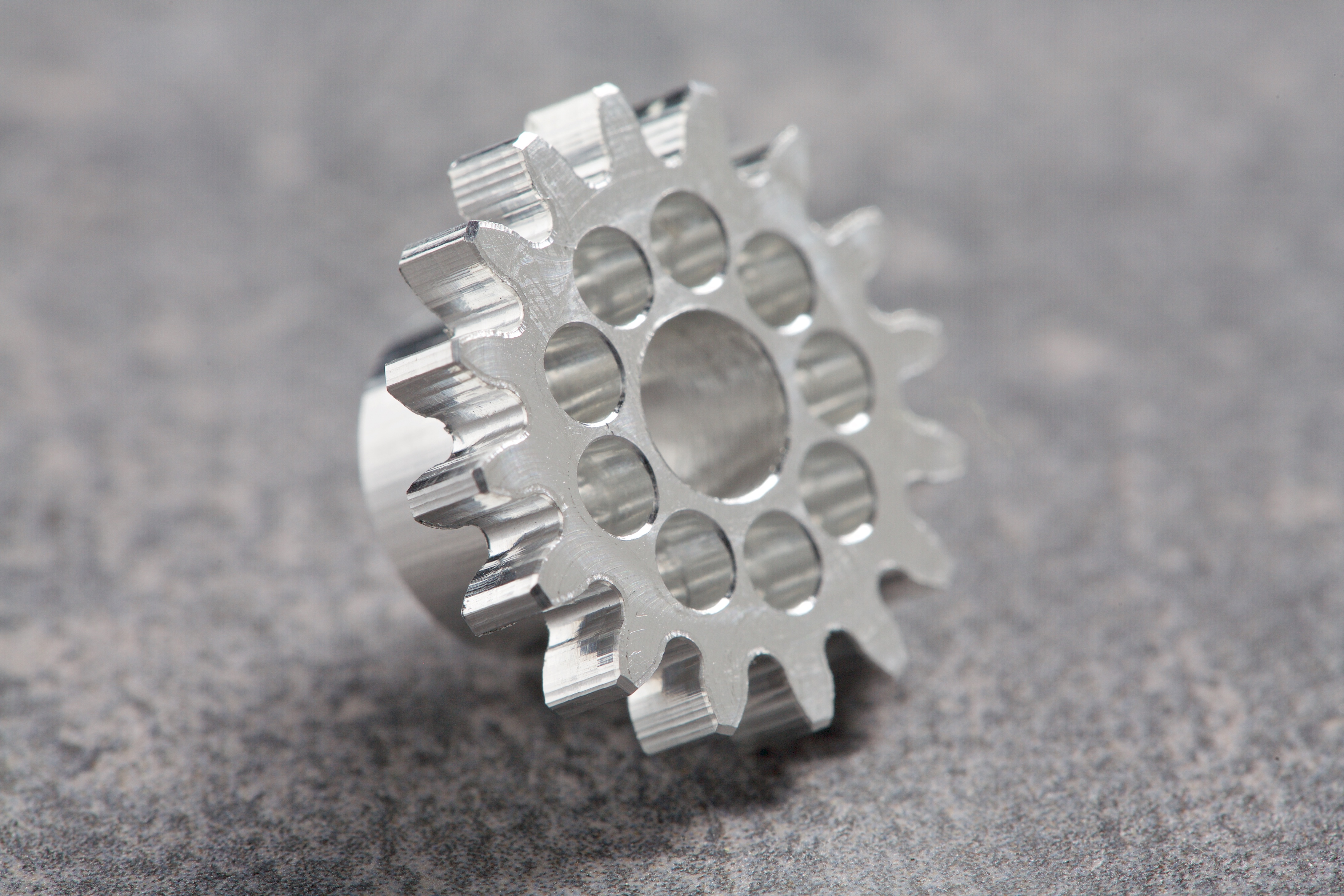
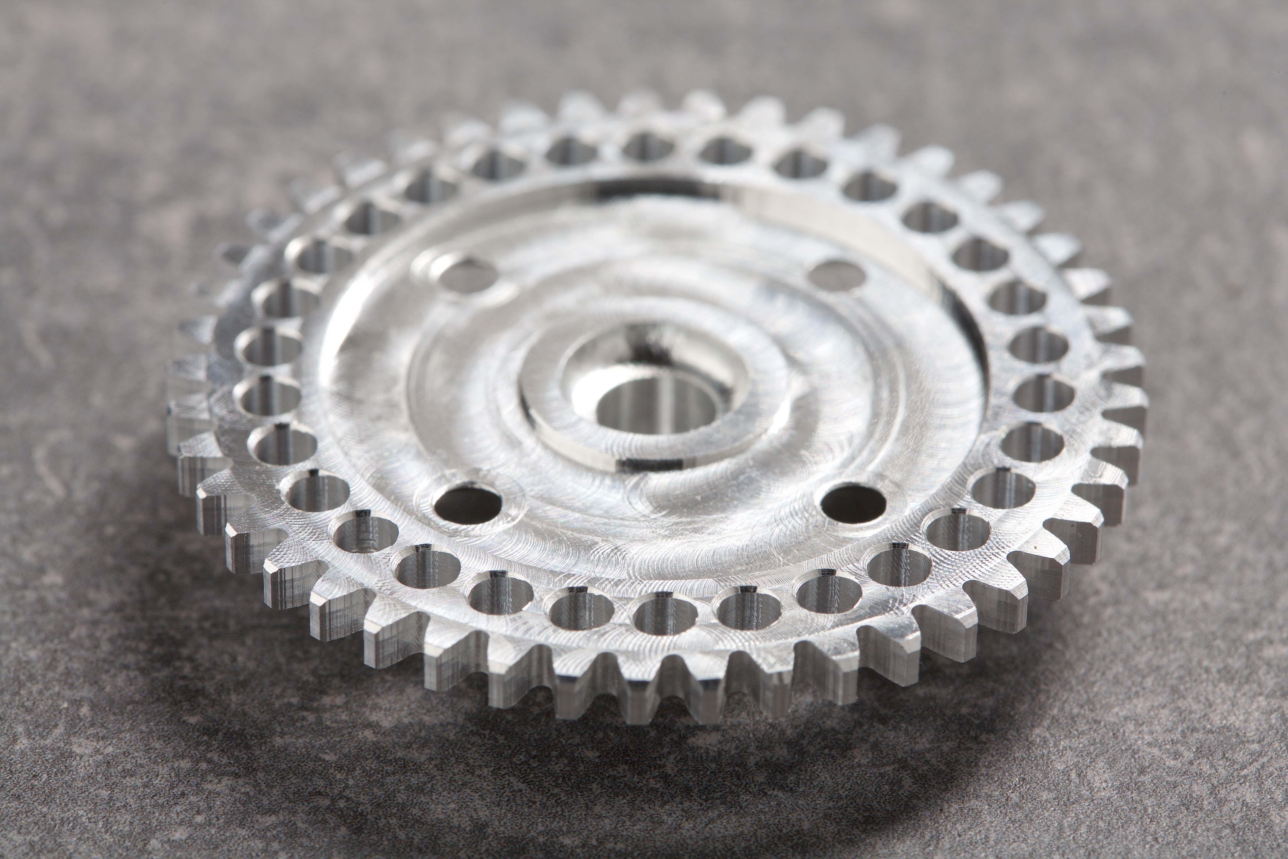
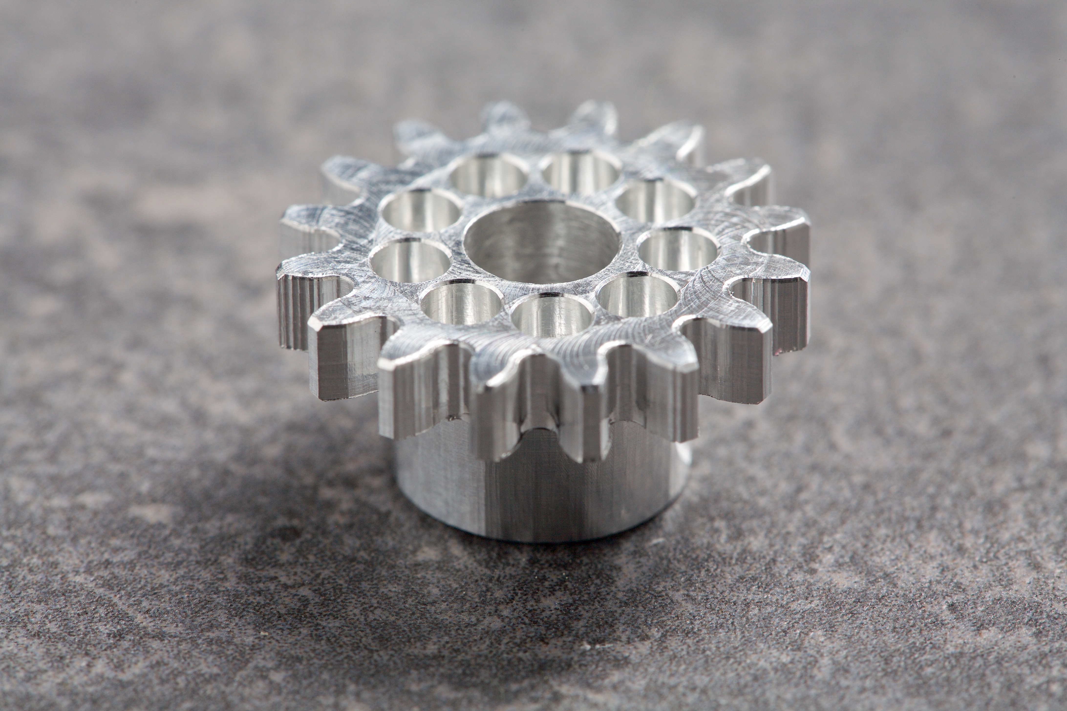
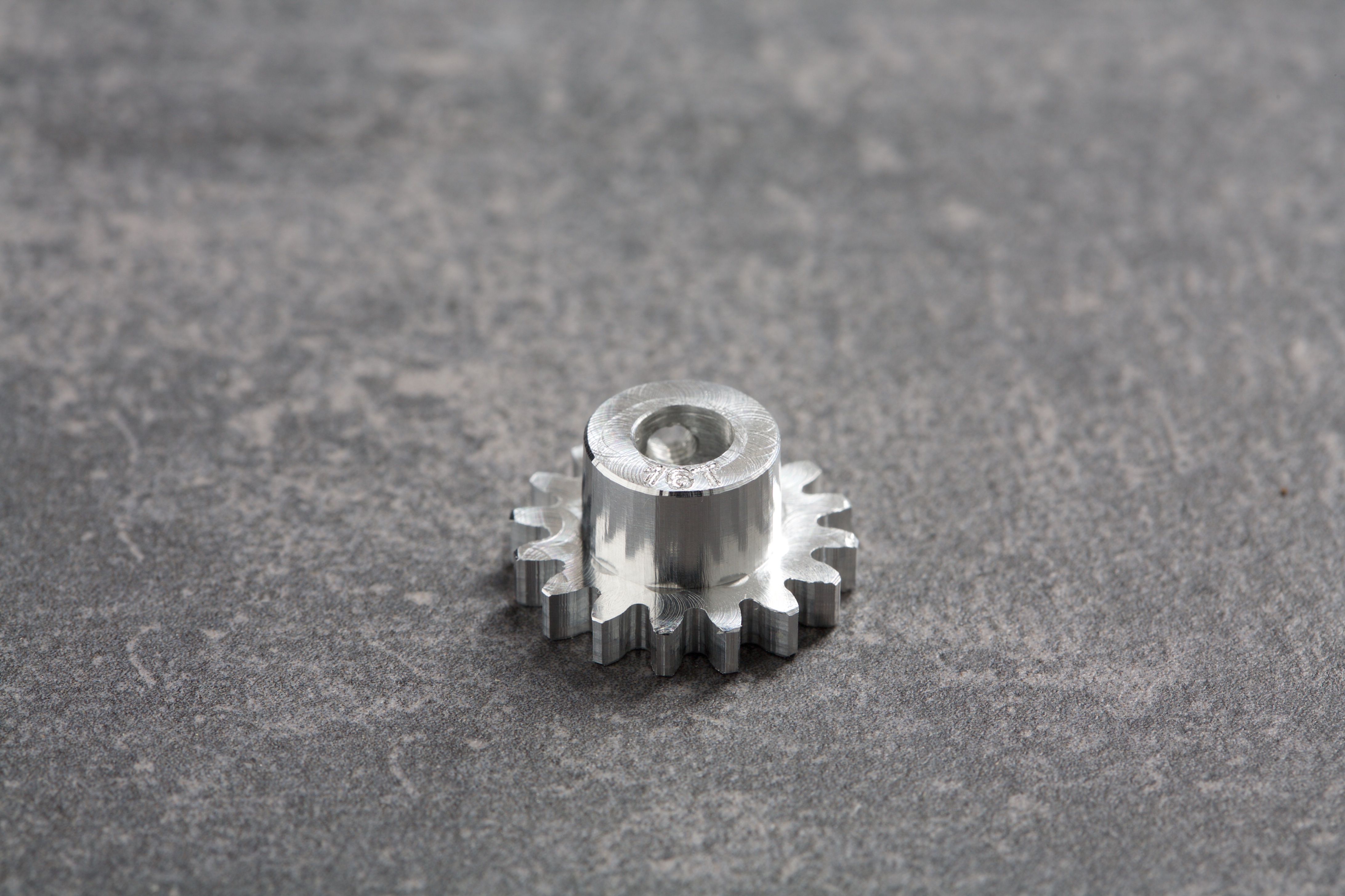
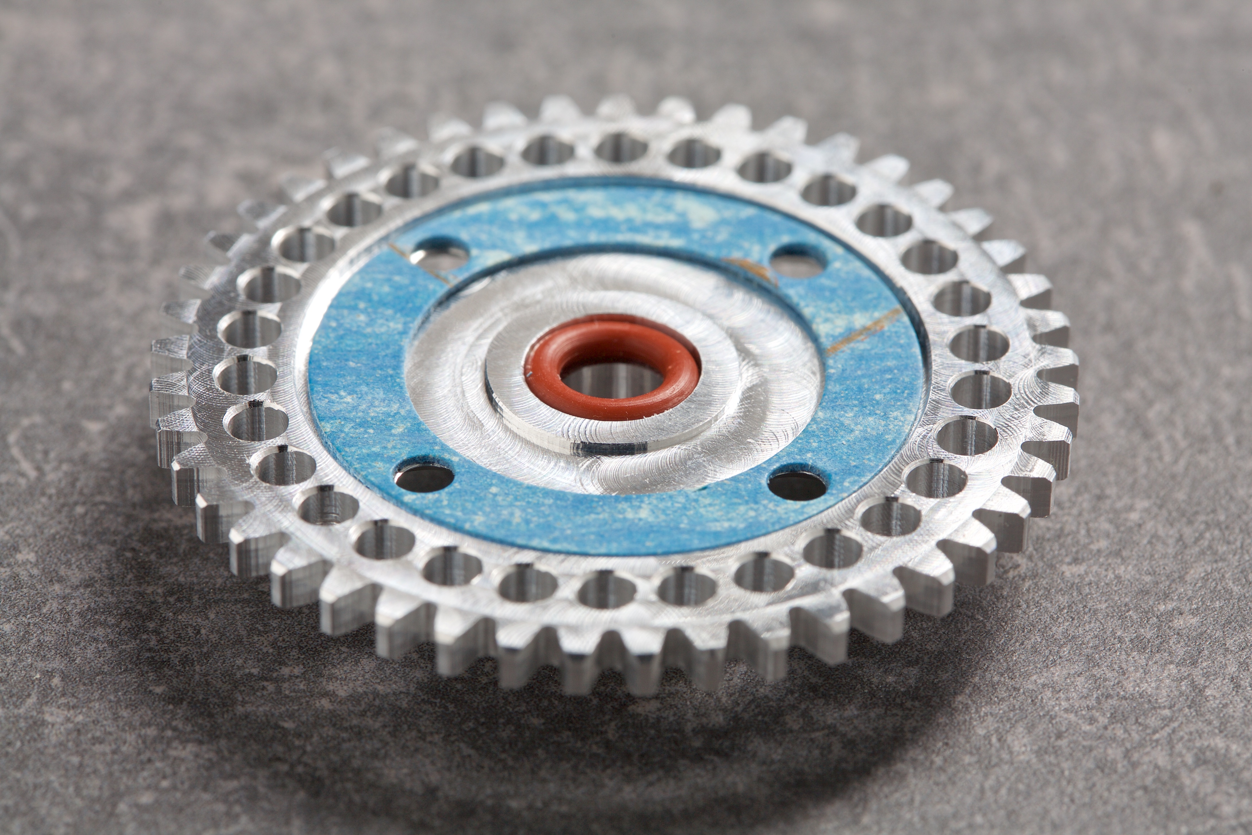
Images showing some of the features of both the pinion and spur gear.
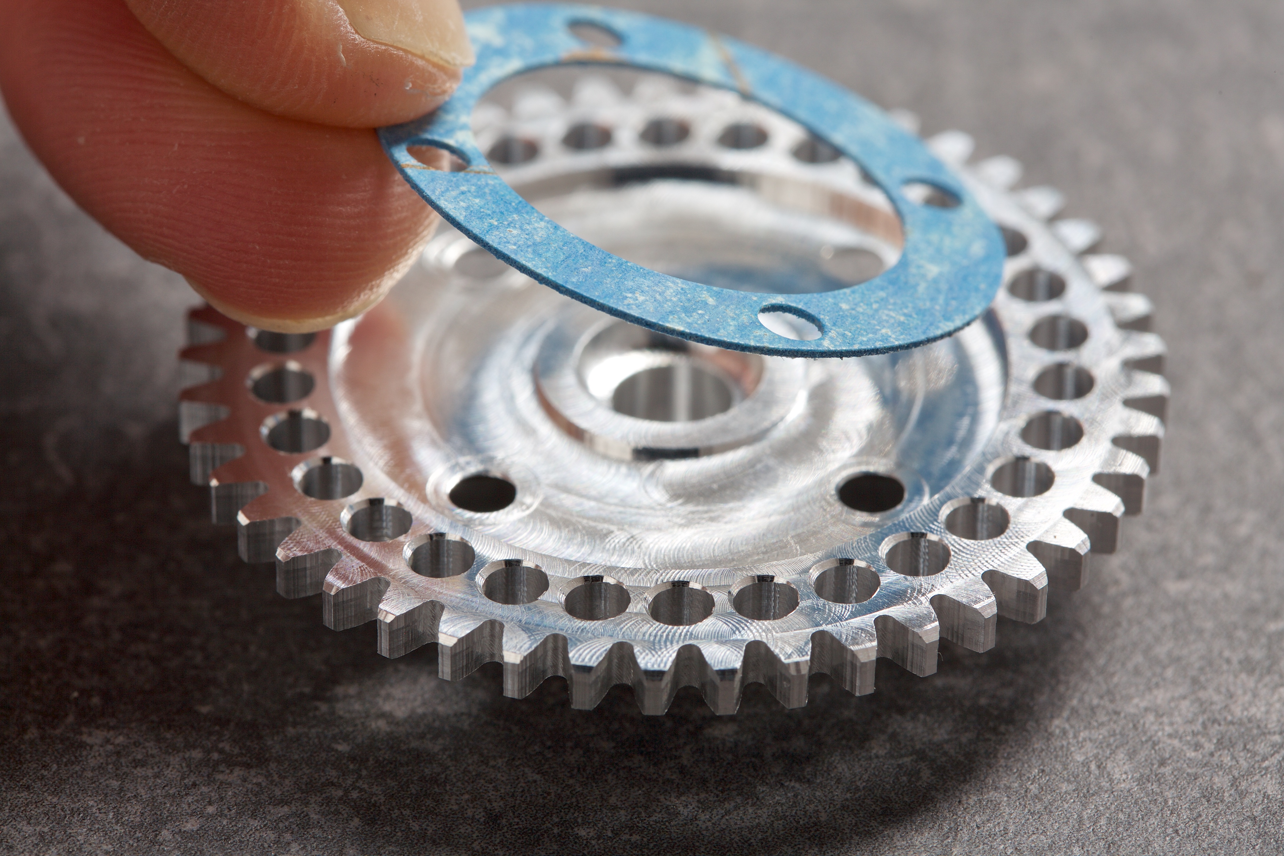
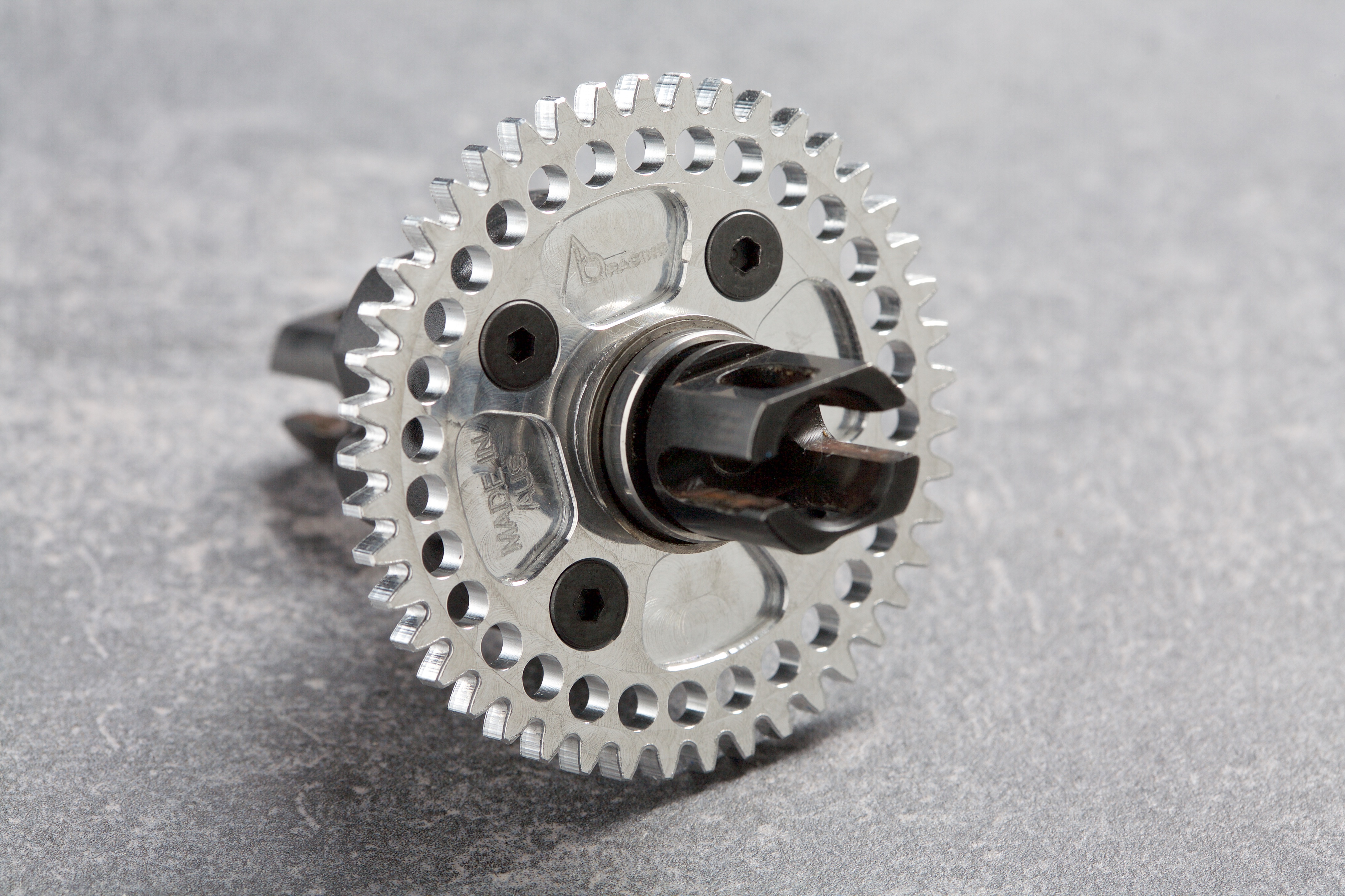
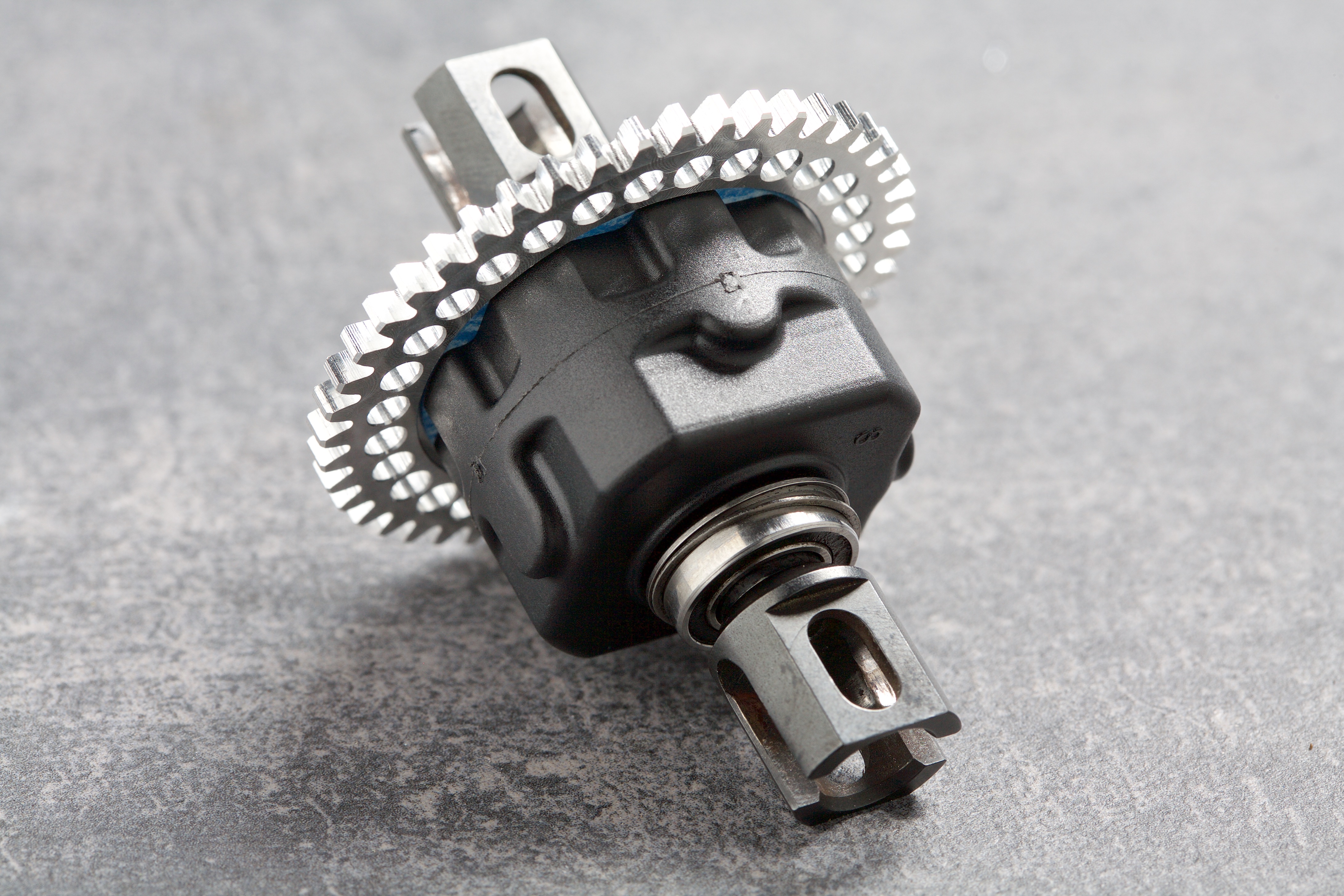
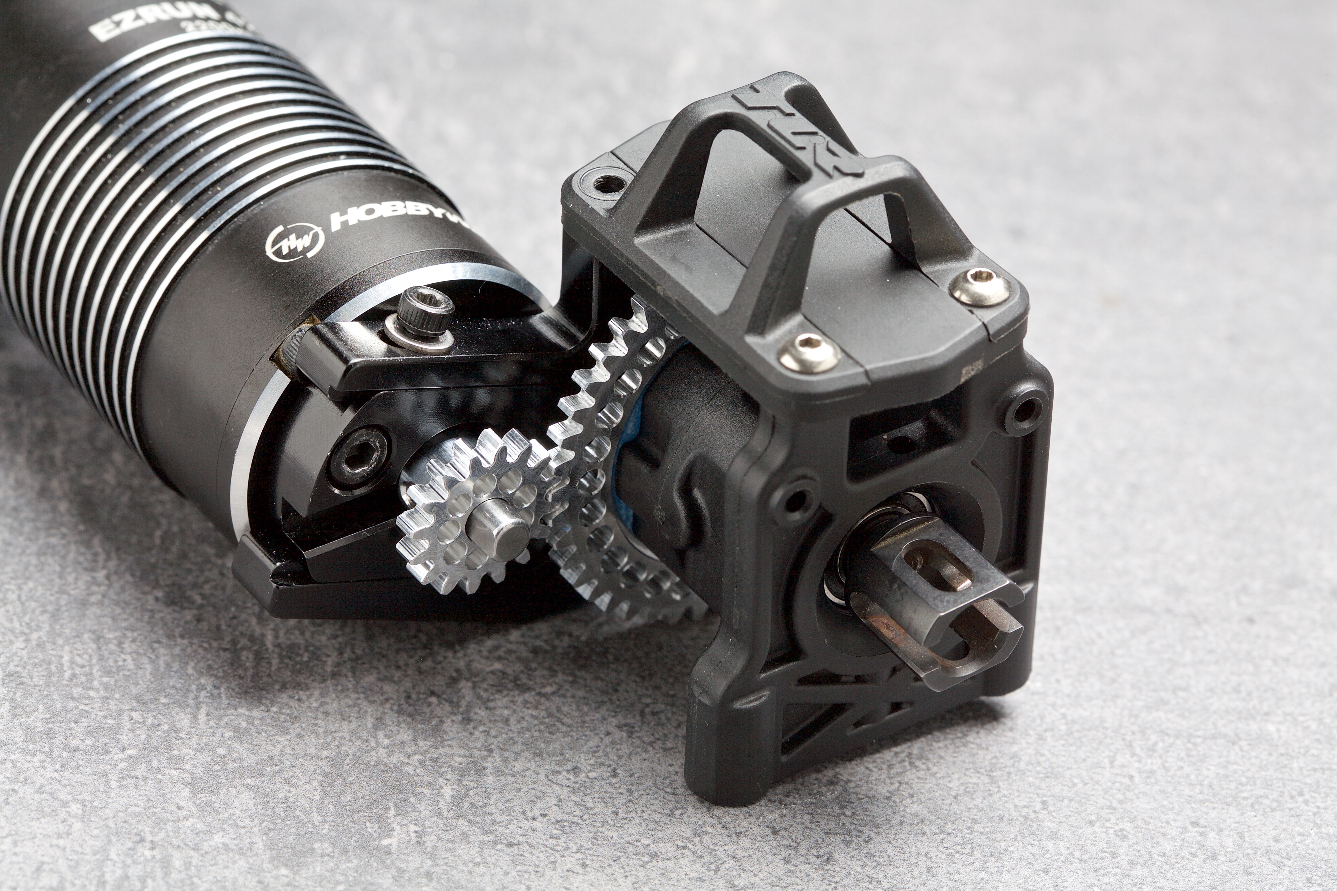
The following images show how the differential is assembled and how the spur and pinion gear fit into the assembly.
The blue gasket and red o-ring help to contain the oil inside the differential.
The following images show the complete centre differential with the spur gear attached.
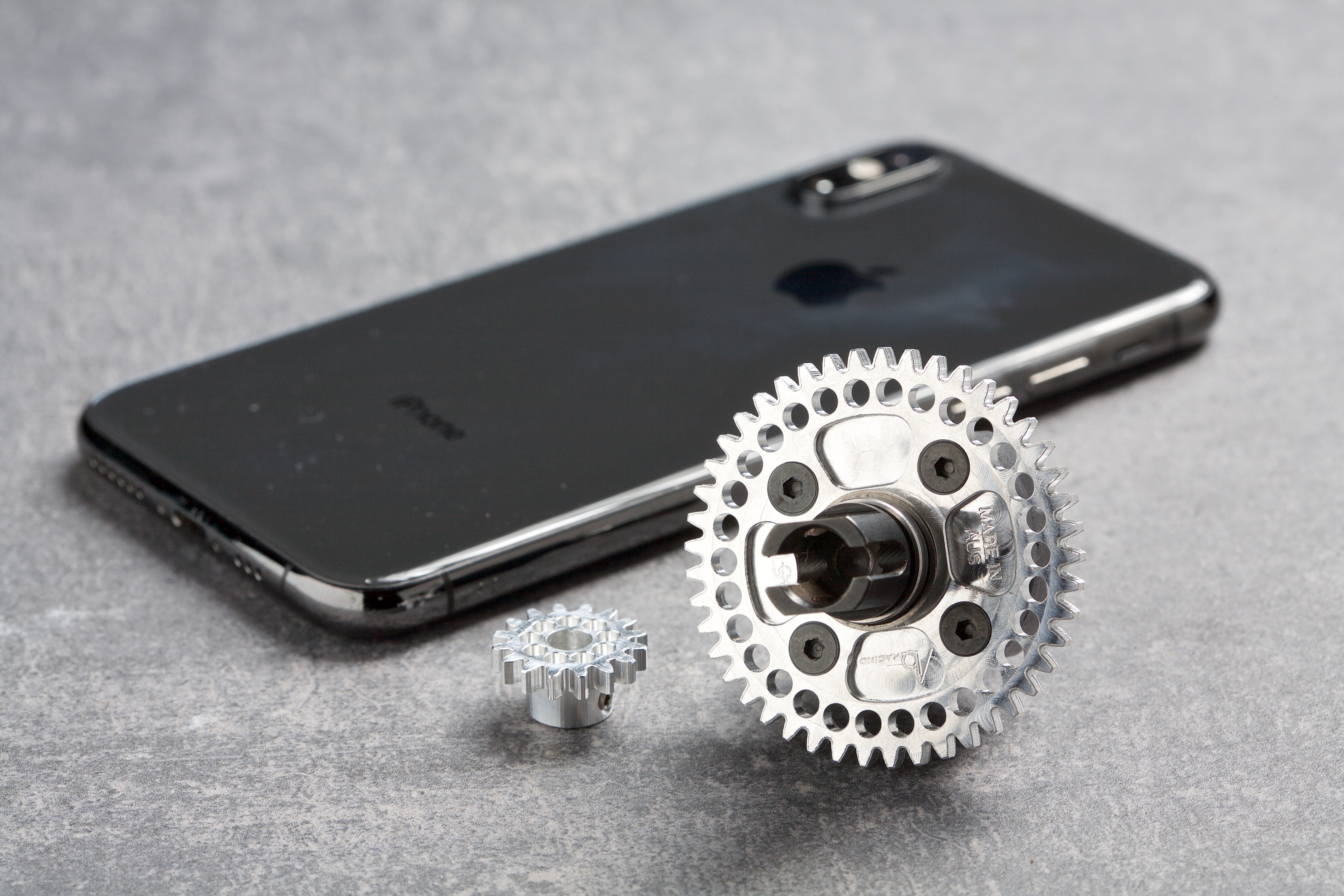
This image shows the scale of the two gears. (Pictured next to an iPhone XS).
An image of the pinion gear attached to the motor and the differential mounted.
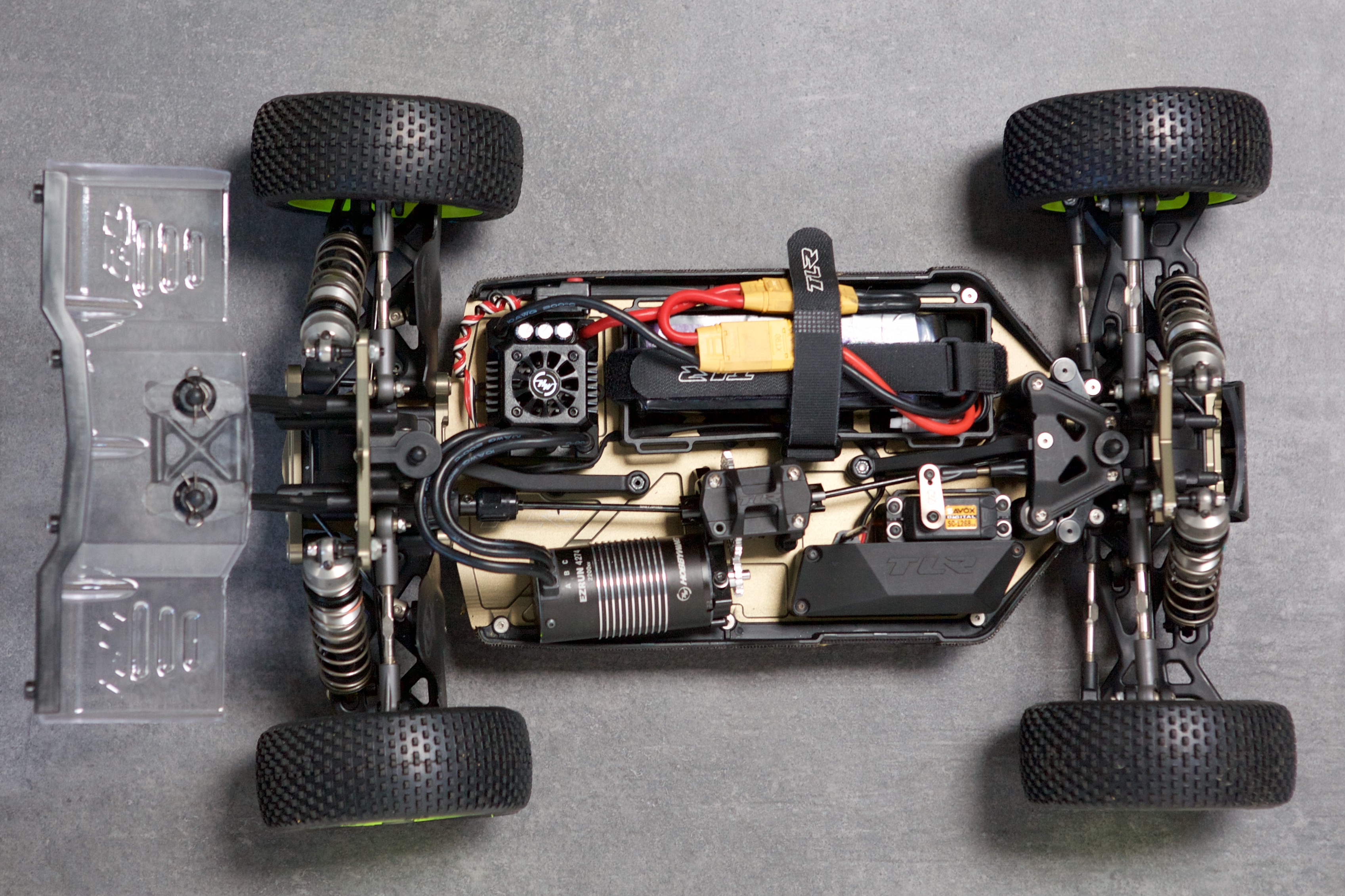
Finally an image of the 1/8 RC buggy that these two gears were designed for.
Thanks for reading, if you have any questions let me know!
 I would love to share. Single flute 8mm cheap Amazon cutter quite decent results!!!