Does anyone have experience or tips on milling aluminum tubing on a Nomad 3?
What are you doing? I milled a 0.5mm groove down 2 mm diameter silver tubes, holding them in wax.
Hi Andy,
Thanks for the reply.
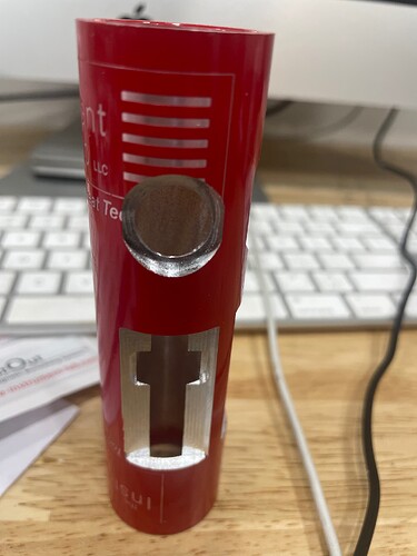
I’m prototyping a new tool for the woodwind repair industry, developing the housing.
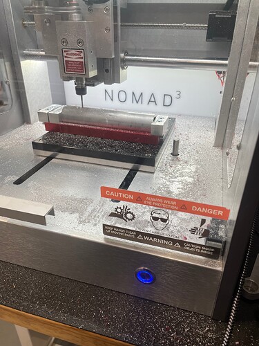
I can just barely squeeze the full-size part into the vise length wise. Just need a way to make sure the part (which is just slightly narrower than the rails of the vise) sits in the center of the vise (maybe a 3D printed V block that fits snugly between the vise rails). My issue is accurately setting the X axis to get a true midline on the tube.
I’m setting the Z axis with the slip of paper between the part and the end-mill. The Y axis is less critical in the design, and I’m lining up the center of the end mill with the edge of the part by eye. Thinking about machining a reference mark in the center of the vise stop block and using that for X alignment.
The full size part in the vise.
A trial run on some scrap… X axis is off midline…
I’ve had the Nomad 3 for 2 years and this is the first time I’ve had the chance to use it. I have a Shapeoko Pro that I use regularly for cabinet making for some of my tool designs.
Love to hear your thoughts!
Best,
Gary J. Gini
Maybe use the touch probe.
Hold the block against the pipe to see it flash green when the bit touches it. Then, manually touch either side of the pipe with the 1/4 probe bit, nudging the bit 0.025mm at a time. Then, calculate the dead centre from the numbers and zero at that position using midi to move to the point. You can so similar with the ends to get x.
Holding it firmly will be tricky as-is as it may rotate with the vibration no matter how light a pass, so thoughts for testing:
- do away with the clamp. As you say, a printed jig with holes to screw to the table is a bit like a water pipe holder. Maybe have them with screw fasteners to pull them tight around the pipe and place them at either end of the pipe.
- Why hold it in lengthways in the vice? Print a grip that fits centrally in the vice with a circular jaw. This will keep the pipe firm. I have printed a vice attachment that holds a mandrel that gets hammered. There is no need for a v-shape unless you intend to have many different diameters; make the outer diameter to get maximum grip. You could give blue tape and glue it as well, but that might be too much belt and brasses
I think the touch probe will light up immediately upon touching it to the pipe because the pipe shares a ground with the machine through the fixture. With a fixture that doesn’t ground the part to the bed that would work out great though.
Big +1 to making a jig for this. I’d probably put a bore in the dead center of a jig, then probe off that bore to find the center of the part that would set x/y. I’d set Z height with the current paper method.
As to the type of holding I’d do with a jig, it would depend on the tolerances you need. But I’d probably lean towards a flexure type vise. The ones where you make a hole slightly larger than diameter of the pipe, put a slit in it, and drop a bolt through to provide clamping pressure. (Split hub shaft collar? Couldn’t find a definitive name)
The whole thing could probably be made with about a foot of mic6 and you’d end up with a relatively low cost fixture that offers a lot of quality of life utility while being pretty darn rigid. The whole thing can bolt directly to the threaded table.
That may be overkill for your needs though. I’ve been accused of over engineering once or twice ![]()
Looking forward to seeing how this issue is handled regardless. I know I’ll be solving a similar work holding issue eventually ![]()
Good point on the grounding of the touch probe; it is annoying. I have insulated items in the past.
There’s nothing wrong with a bit of engineering, over or not.
Interesting project - I’ll be cutting a tube a similar size, but off center. I’ll check in to see what you come up with, and let you know if I get a good idea.
My current idea involves clamp-on shaft collars bedded in a block of some sort, as my 5C collet block is too long to put the part in and still make the needed cuts. I might try an ER-type collet block instead. I’ve been putting the 5C block on my Smithy mill but need the CNC precision soon.
This topic was automatically closed 30 days after the last reply. New replies are no longer allowed.


