Hello!
My goal is to cut out 2D chess pieces with engraved pocket areas. I don’t own the CNC machine, so I’m using Carbide Create at home to create the c2d file and then travelling to the shop to use Carbide Create Pro to generate the gcode and run the piece.
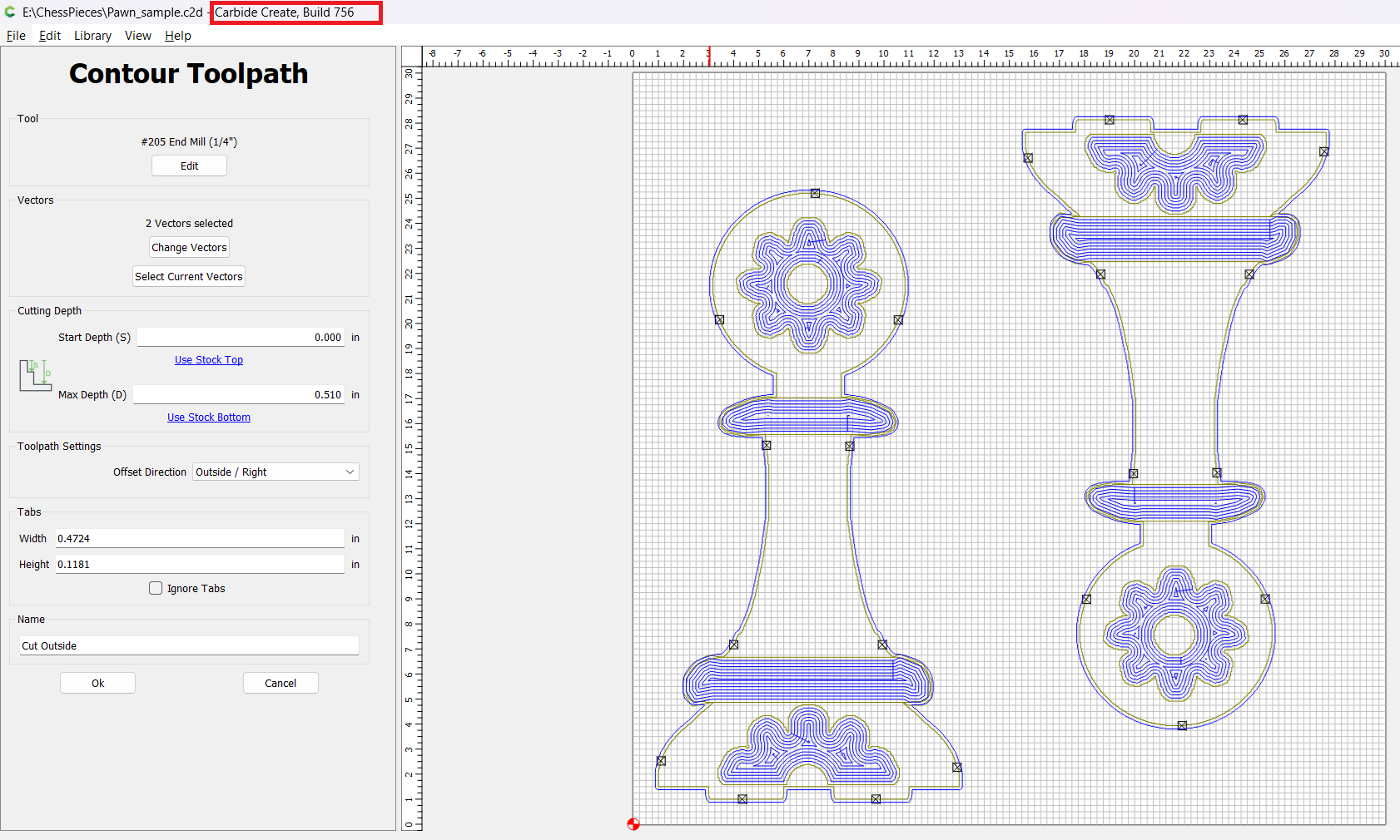
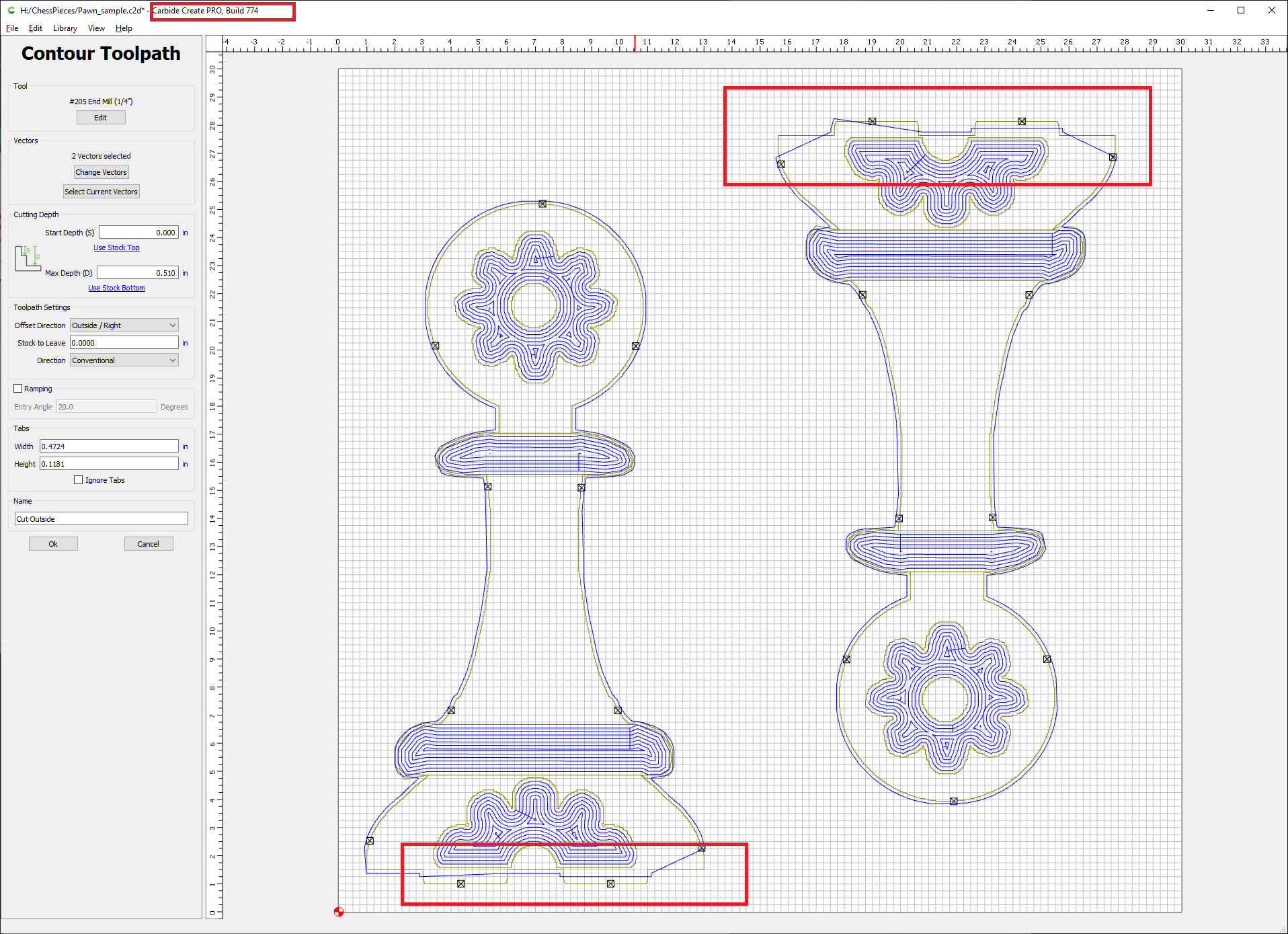
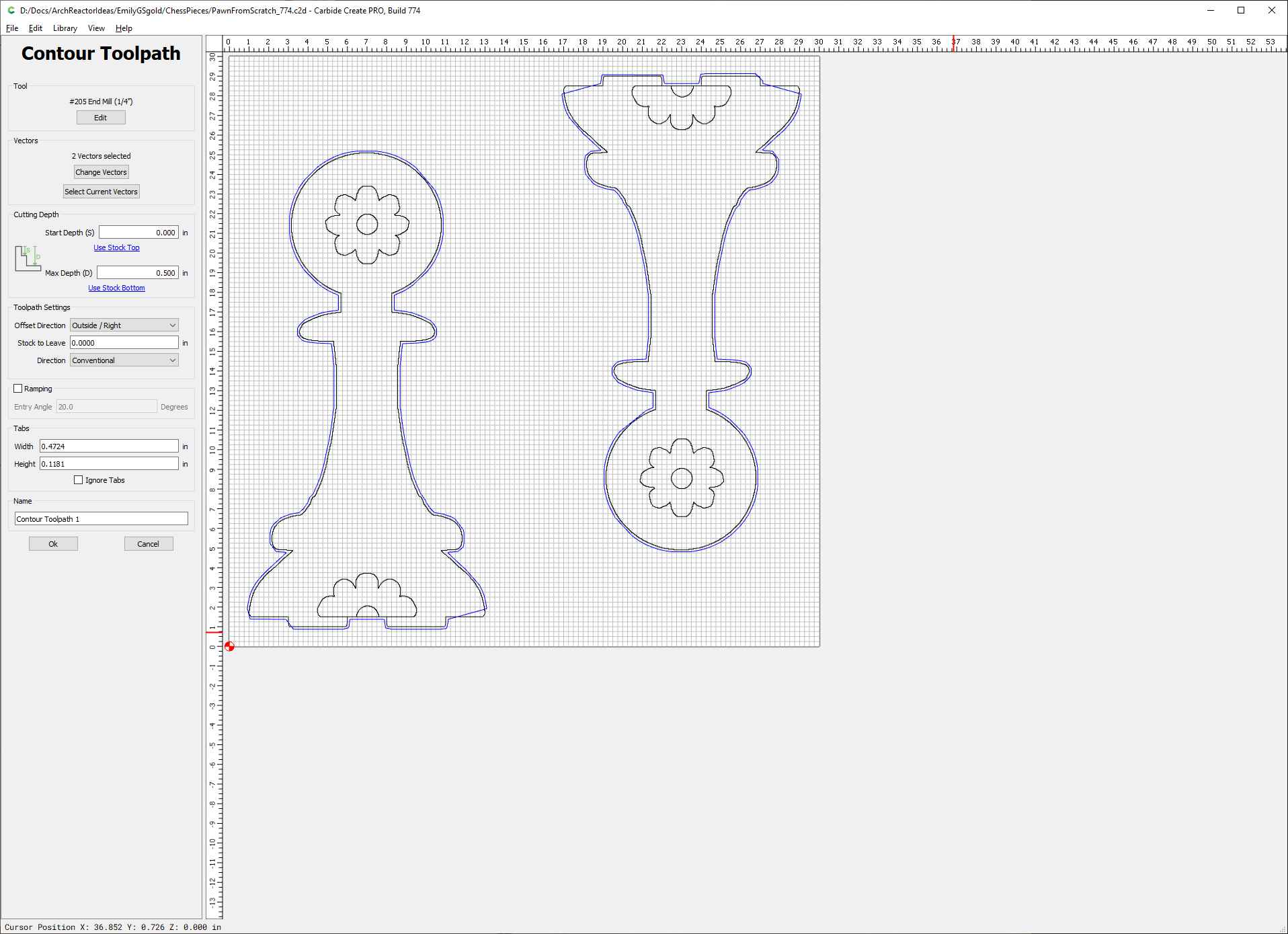
My problem is that the contour toolpath is created differently in build 756 than it is in 774. It seems fine in 756, but 774 is cutting through pieces of the design at the bottom where I have “teeth” to mate with the base. I’ve got screenshots and a sample file that will hopefully make the issue obvious.
Is this a bug? Am I doing something wrong? Is there perhaps some non-obvious bad geometry in my file?
Thanks for the help!
Pawn_sample.c2d (340 KB)
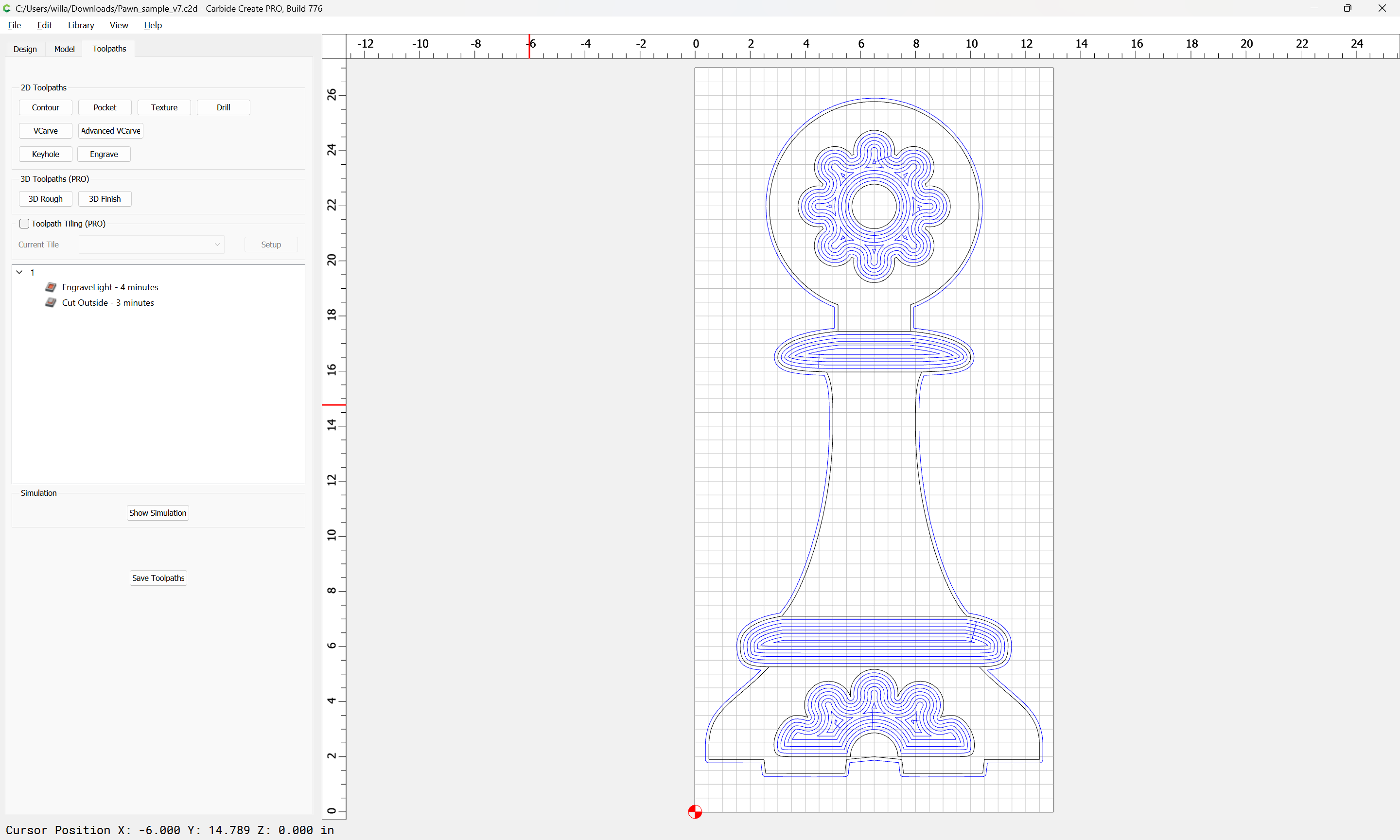
It’s likely a bug that is fixed in build 776. It’s available on the CC Beta page:
Crashes in 776 — we’ll see what can be figured out.
1 Like
Interesting… makes me suspicious that it’s a geometry problem. I started with the pawns, so this model has seen a lot of tinkering and copy/paste.
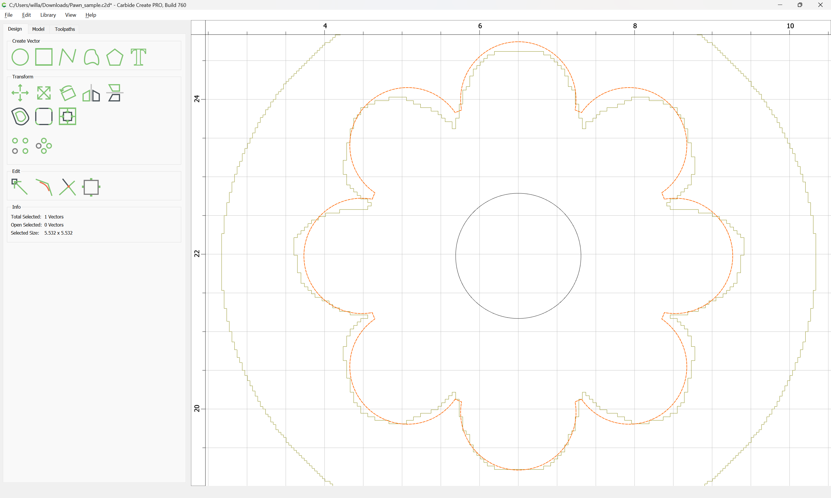
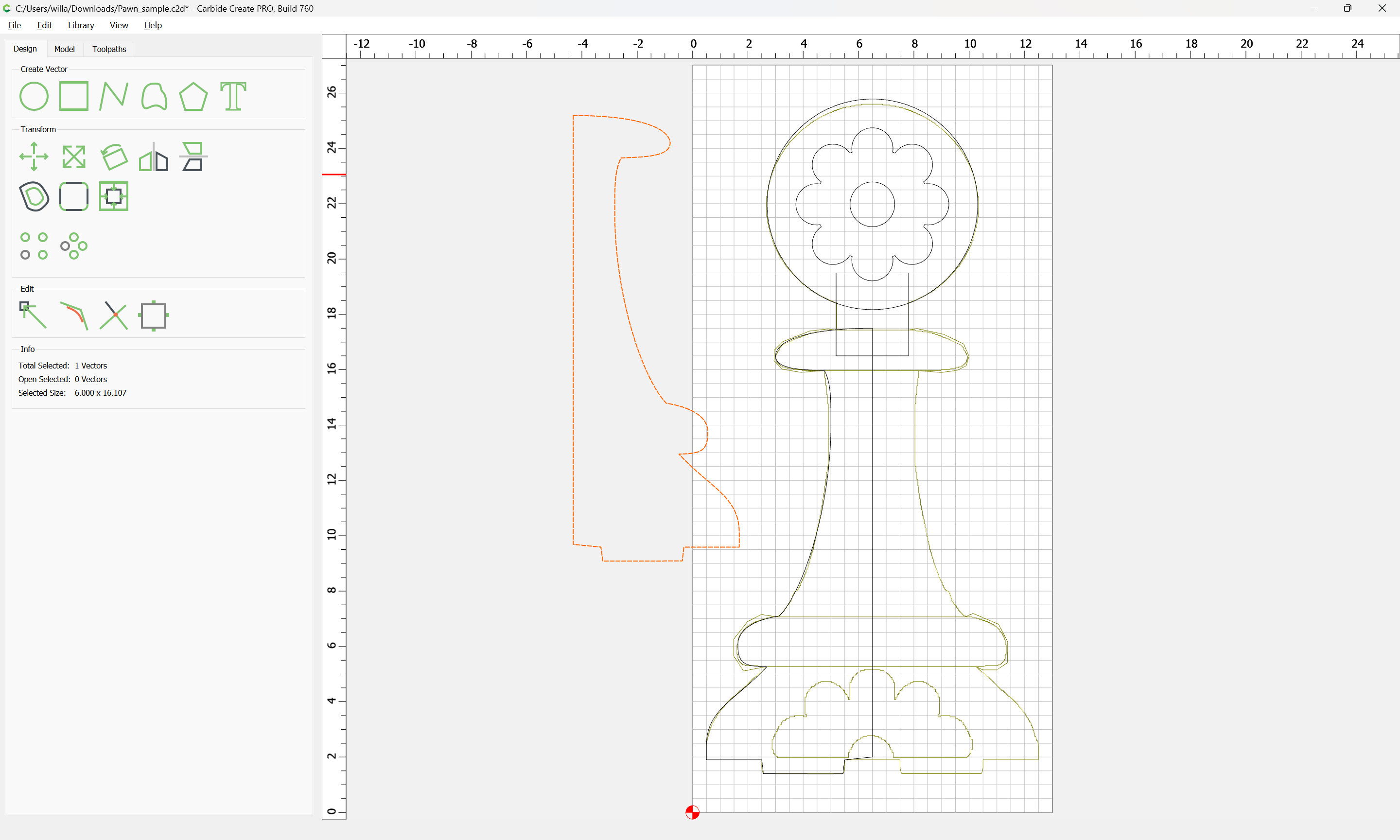
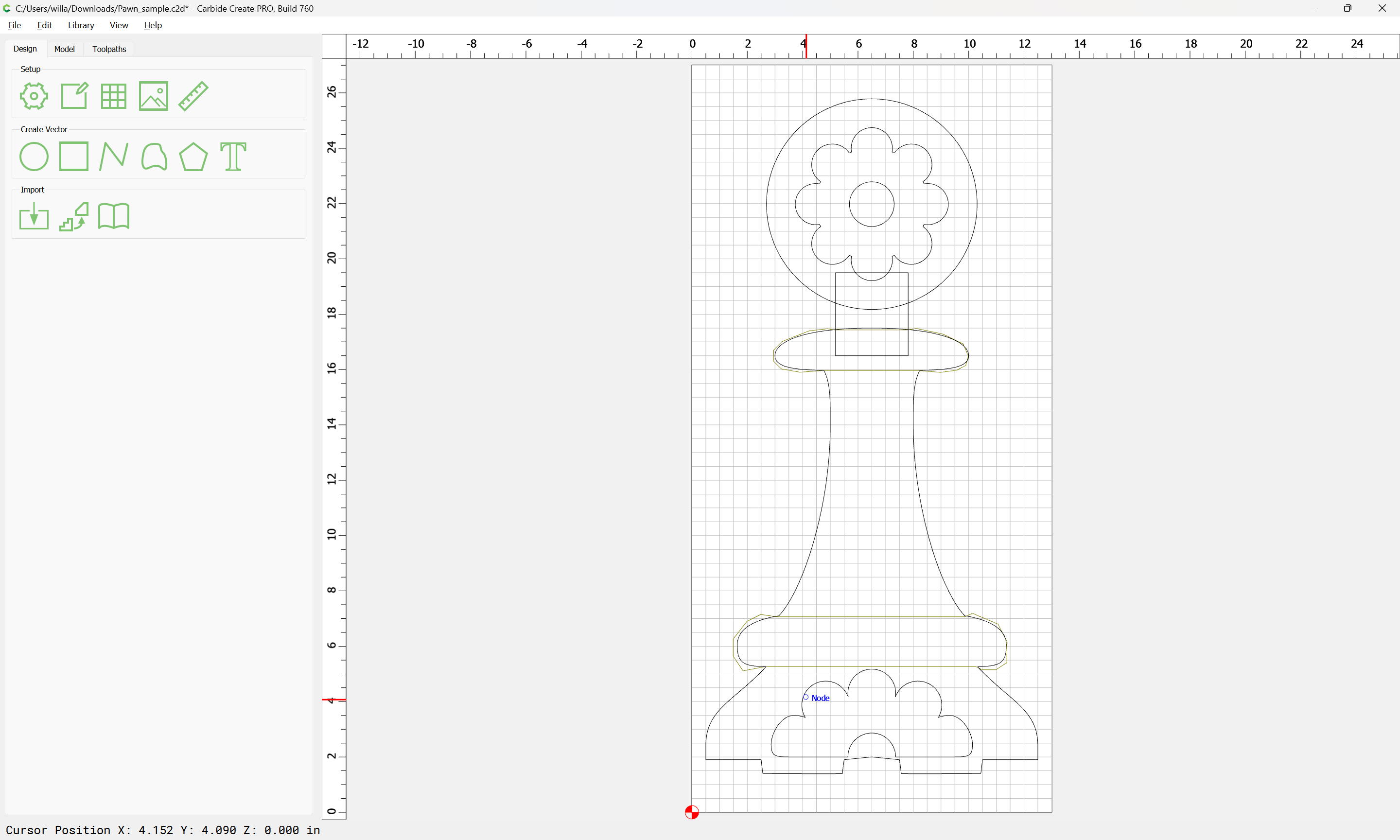
One quick check would be to re-draw:
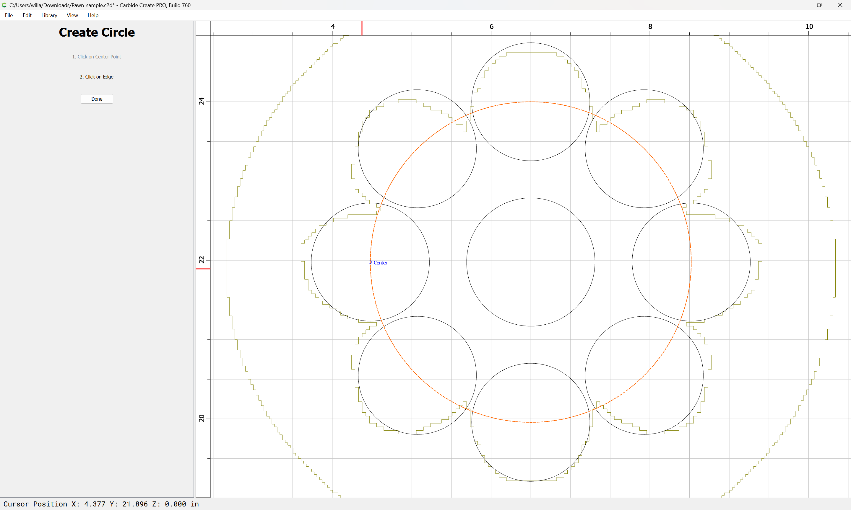
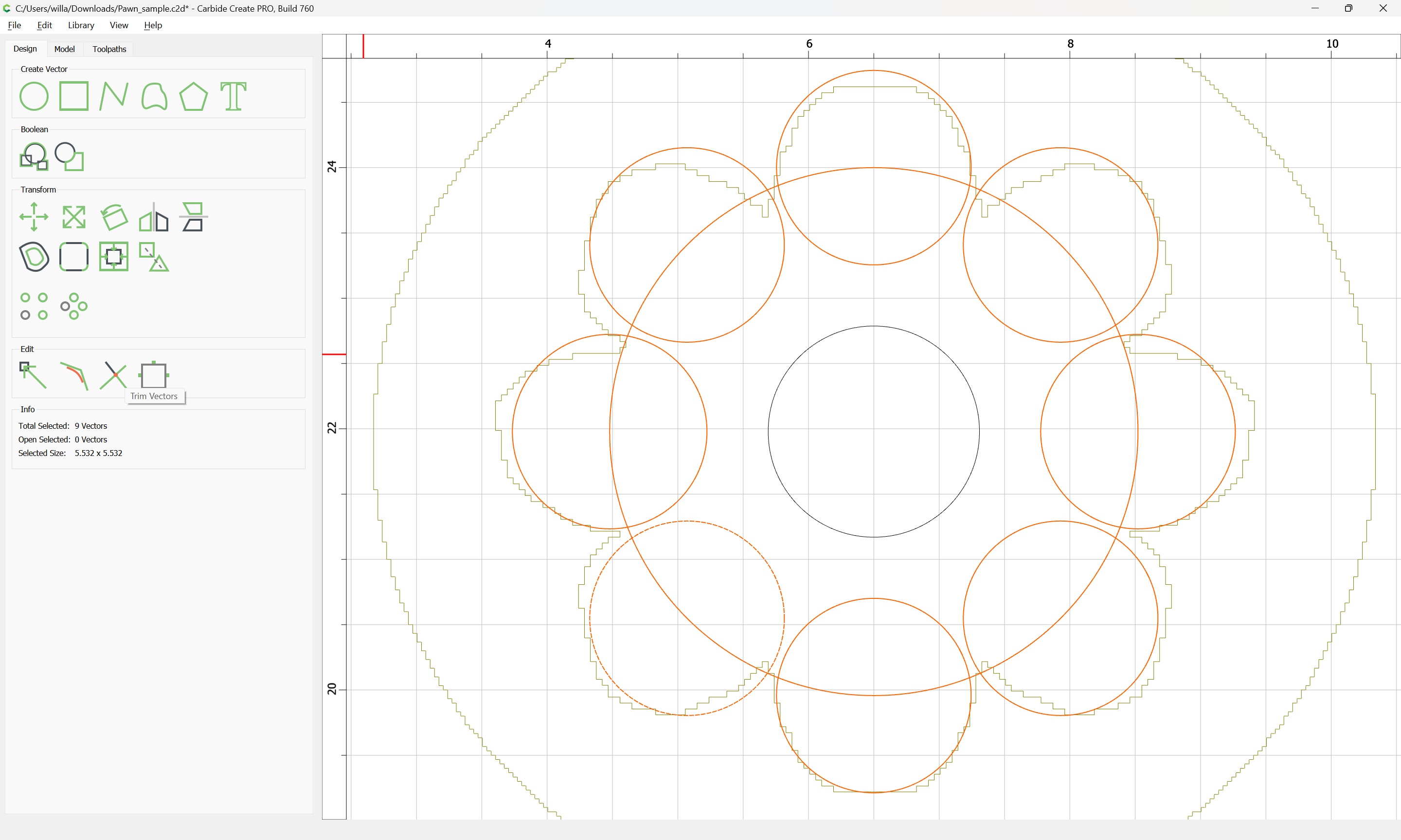
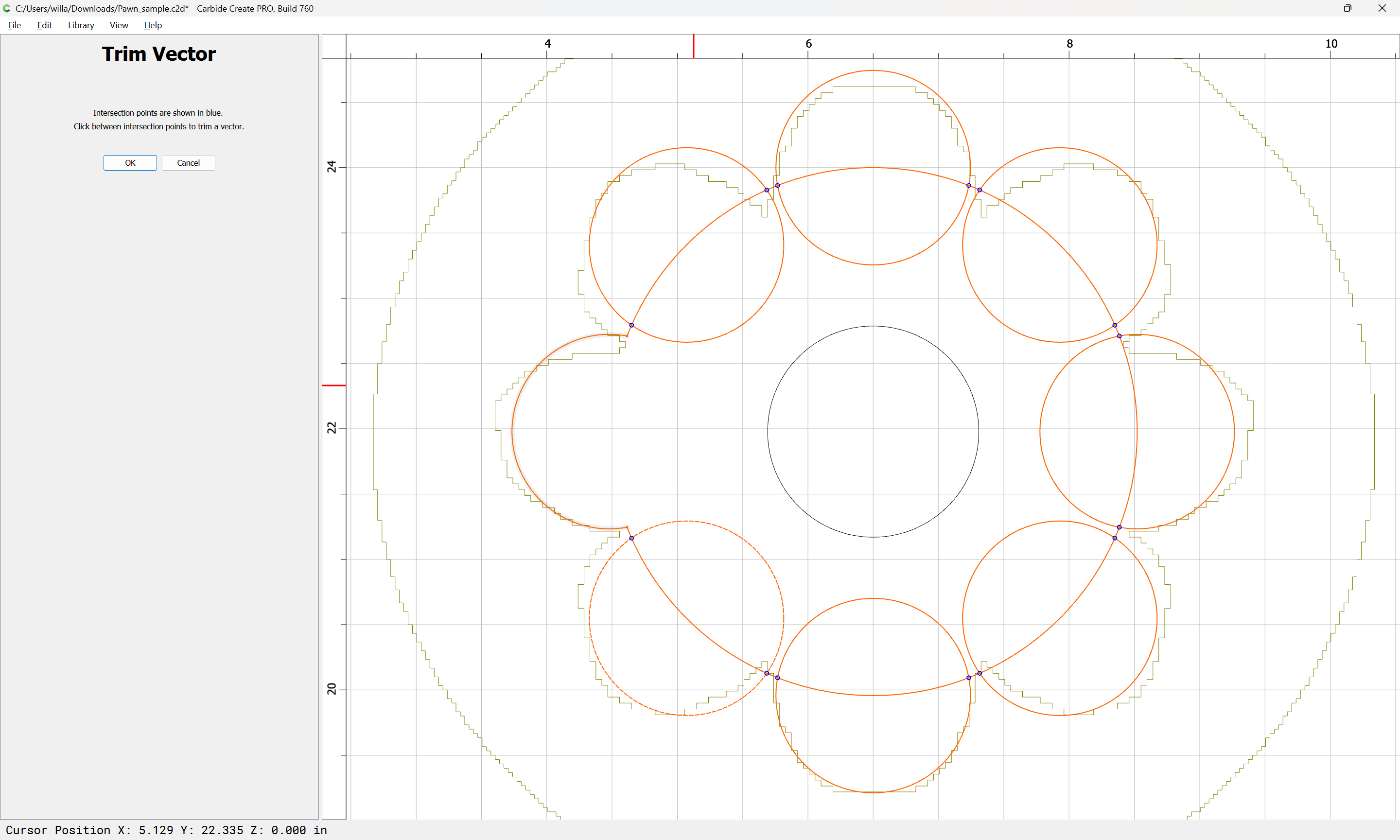
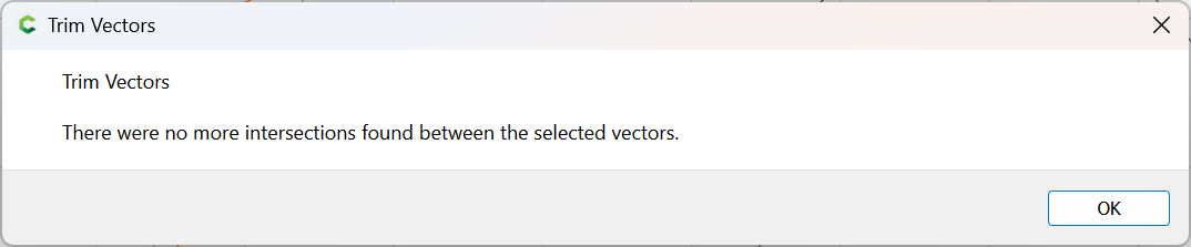
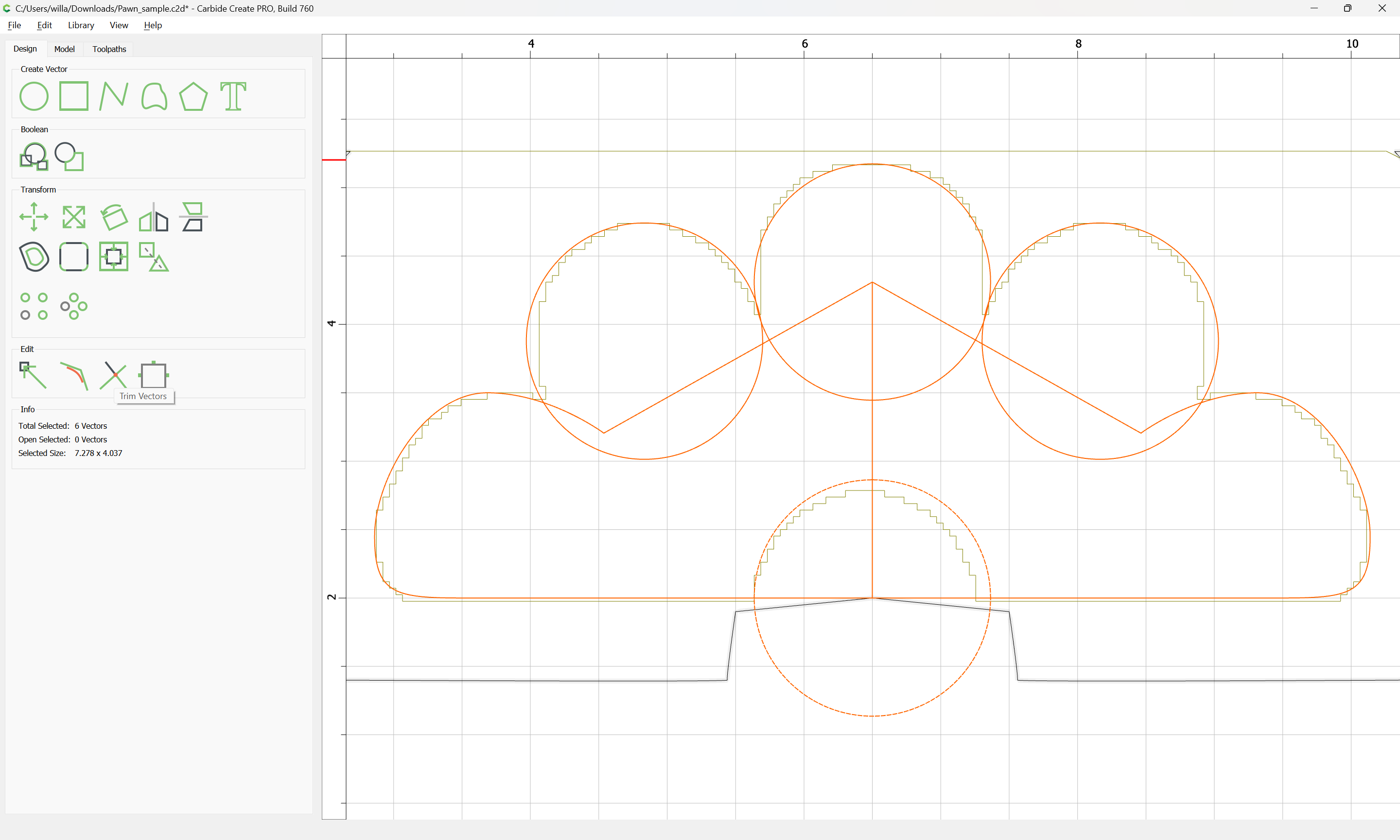
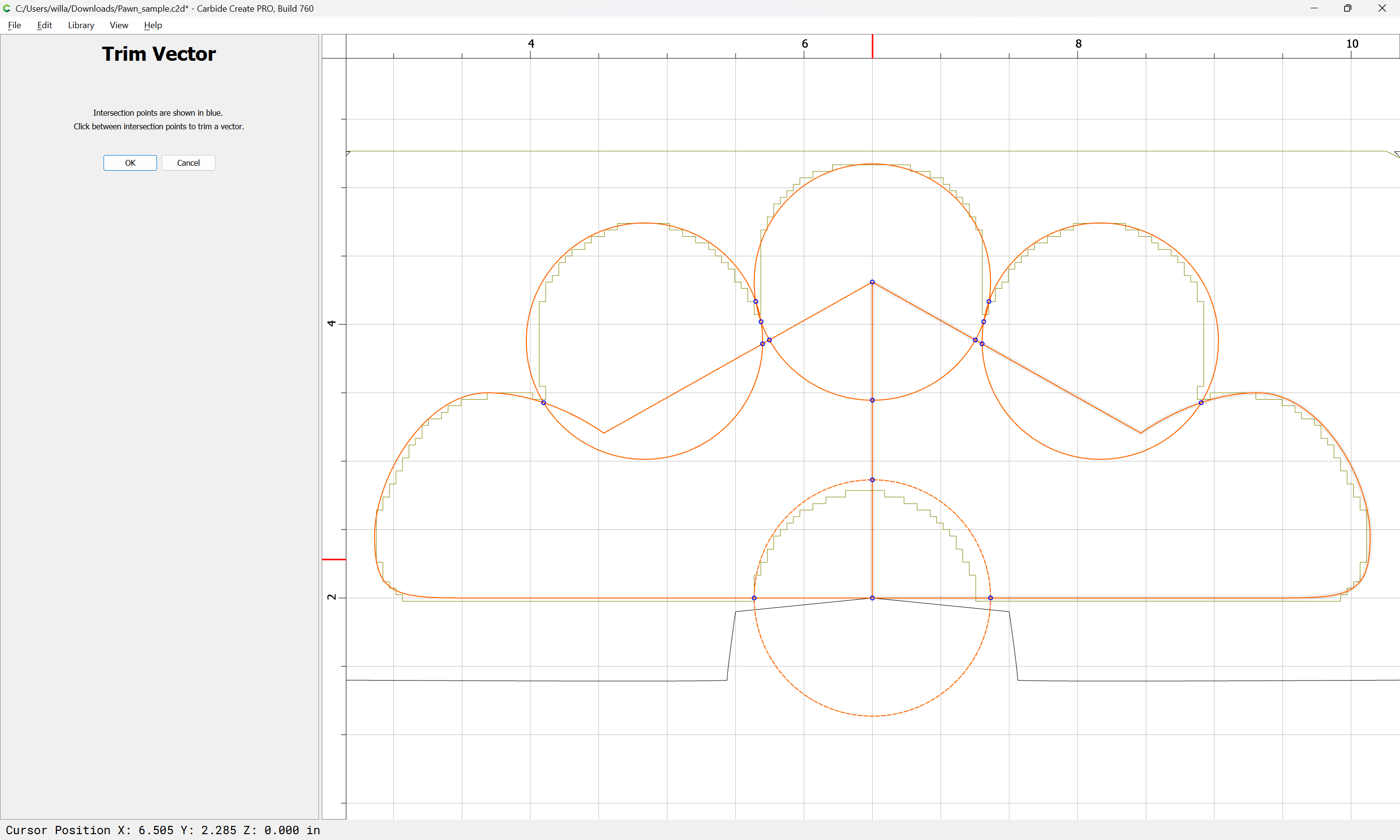
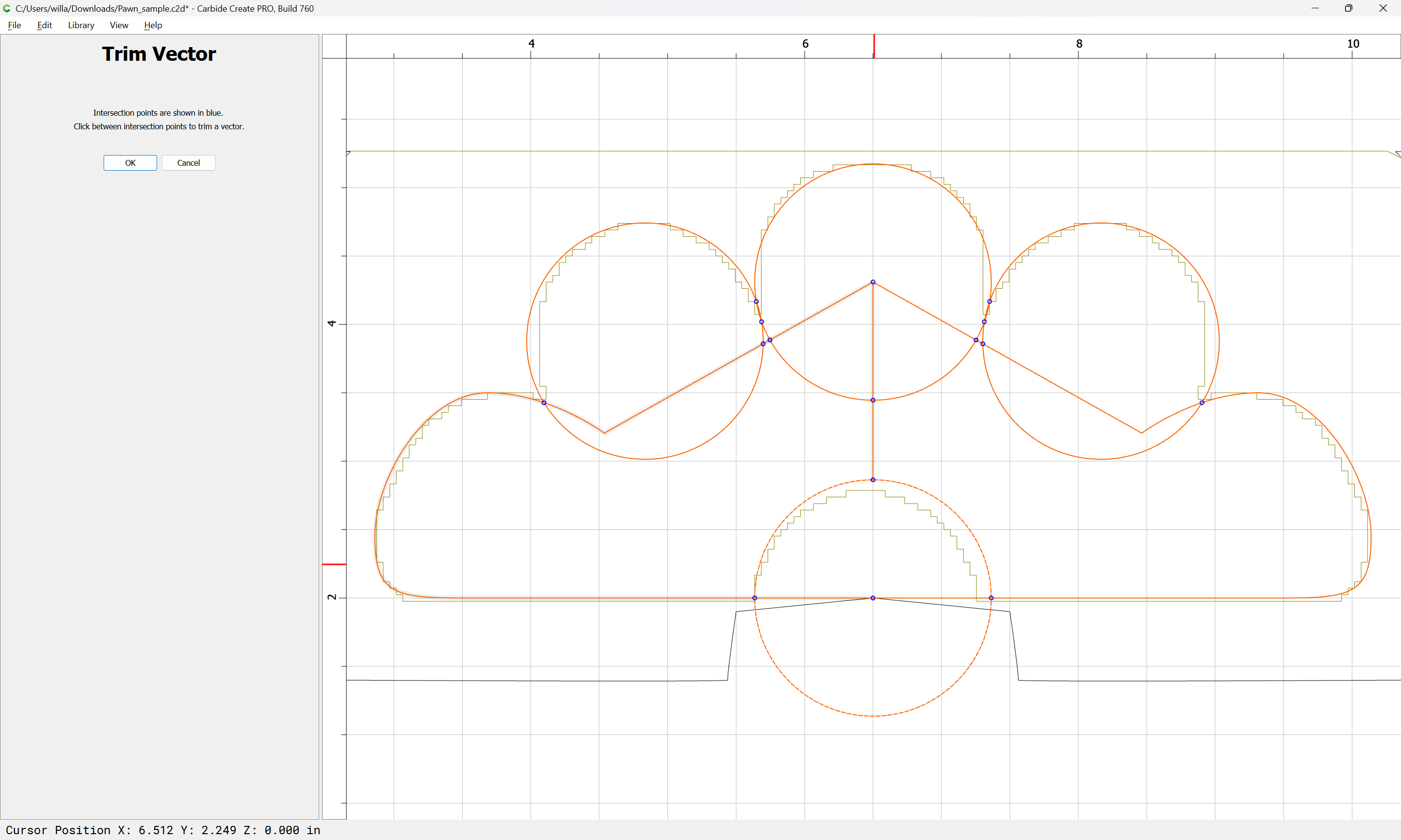
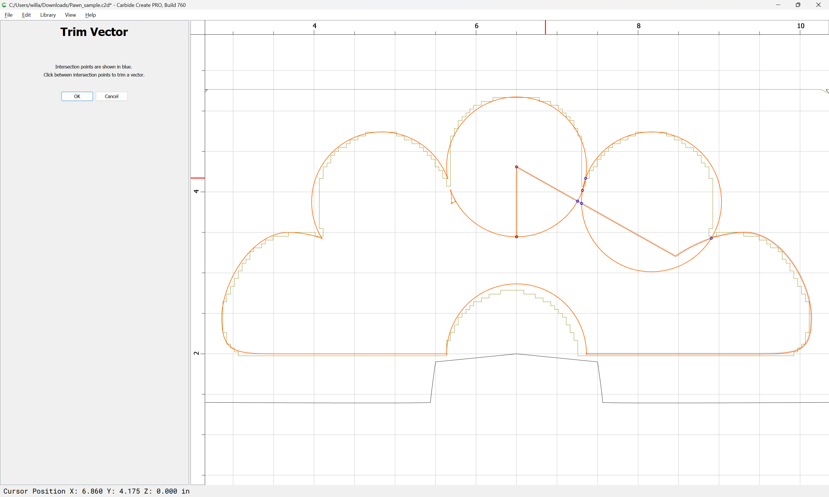
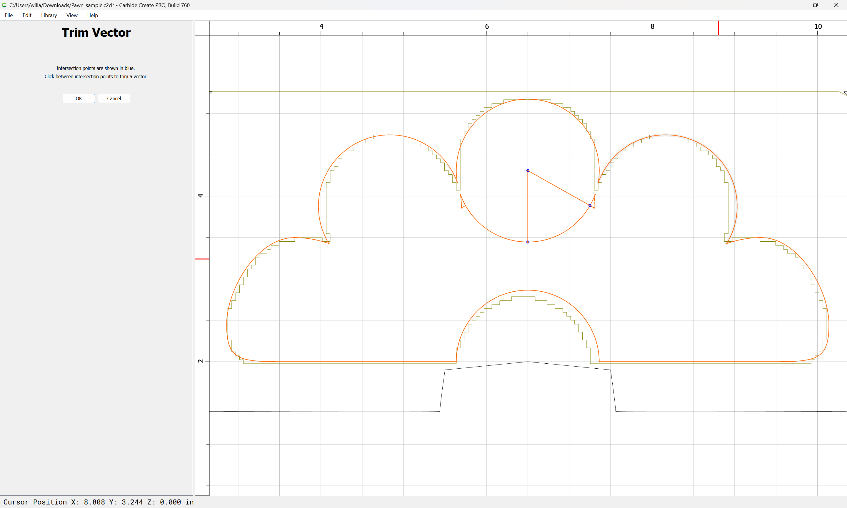
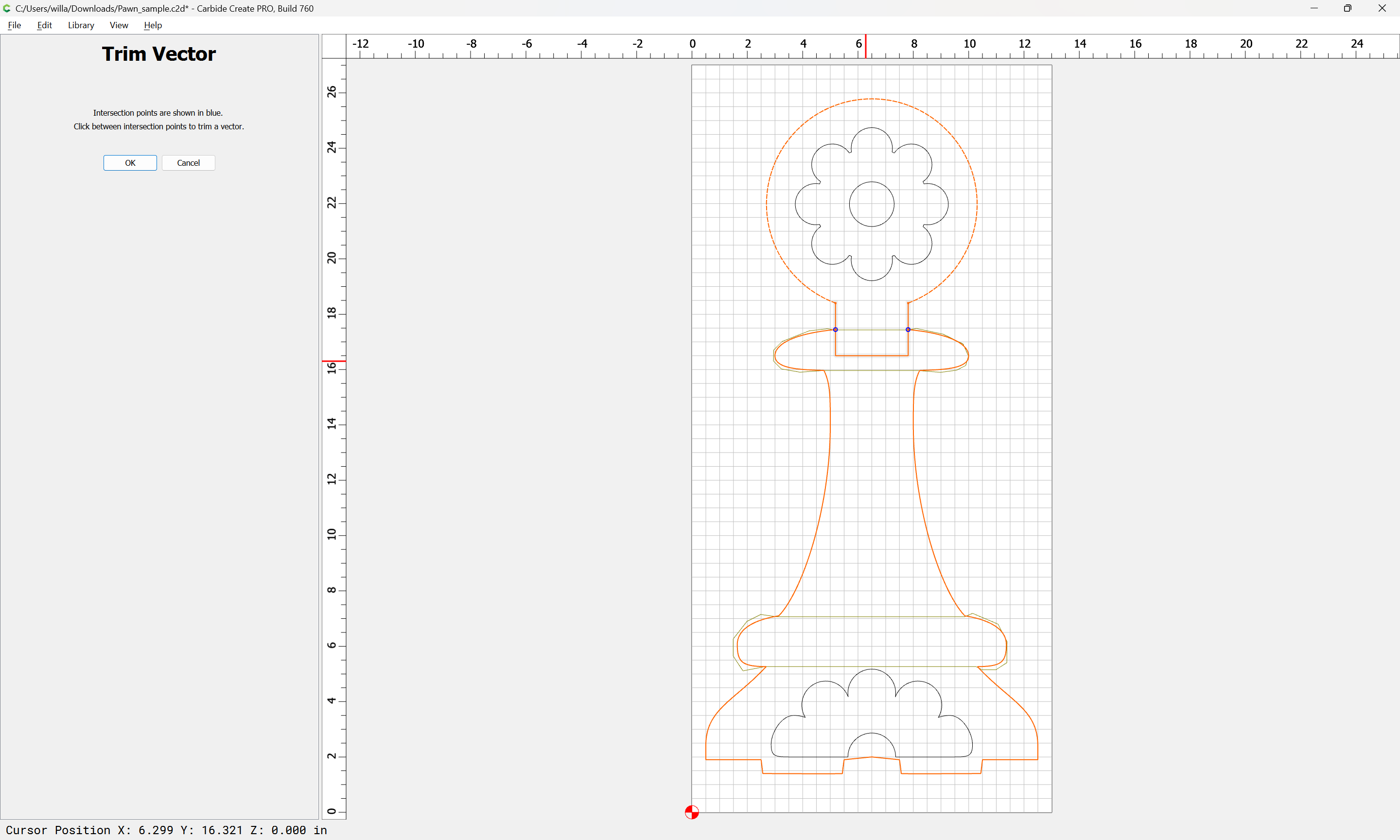
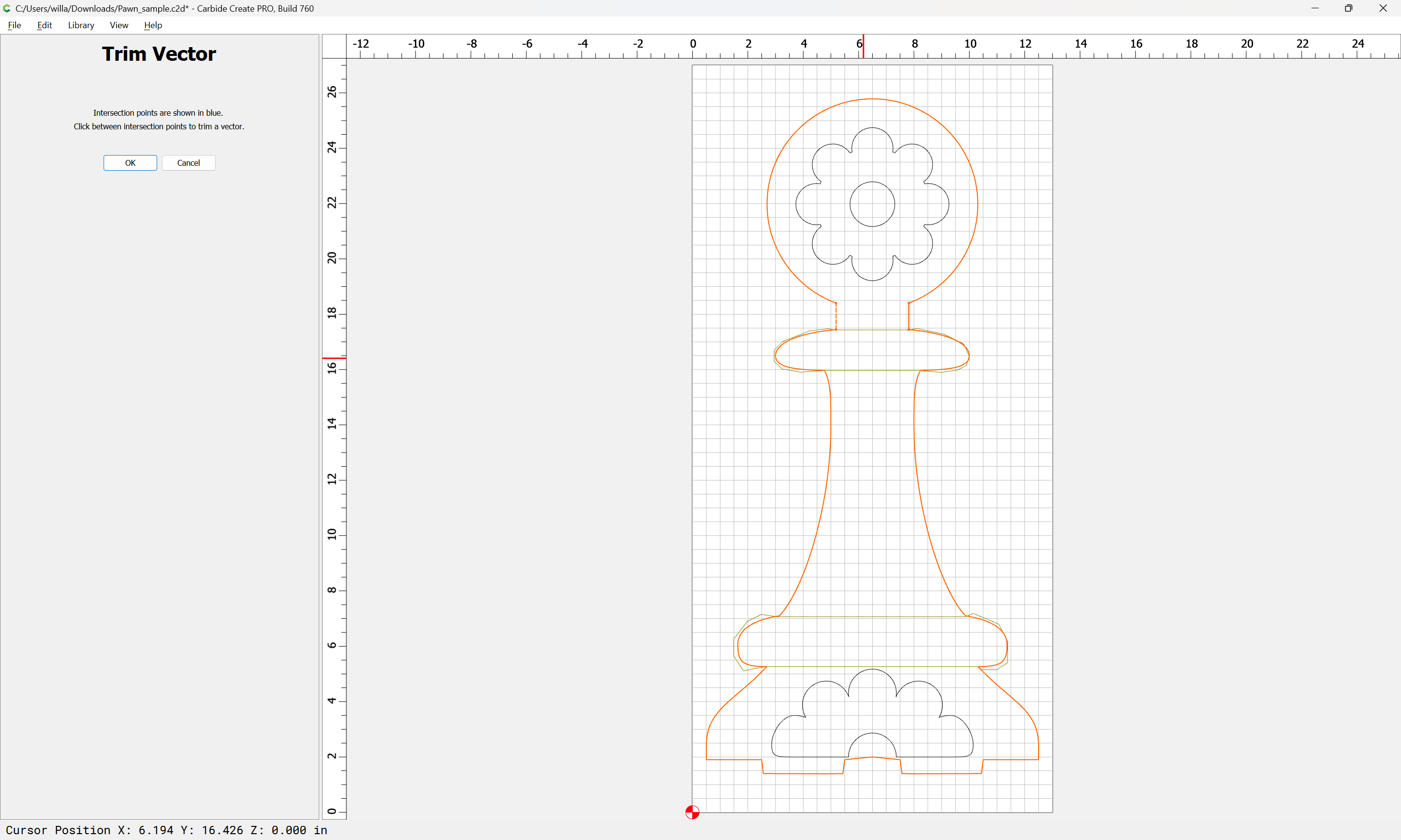
Use Trim Vectors to remove unwanted geometry:
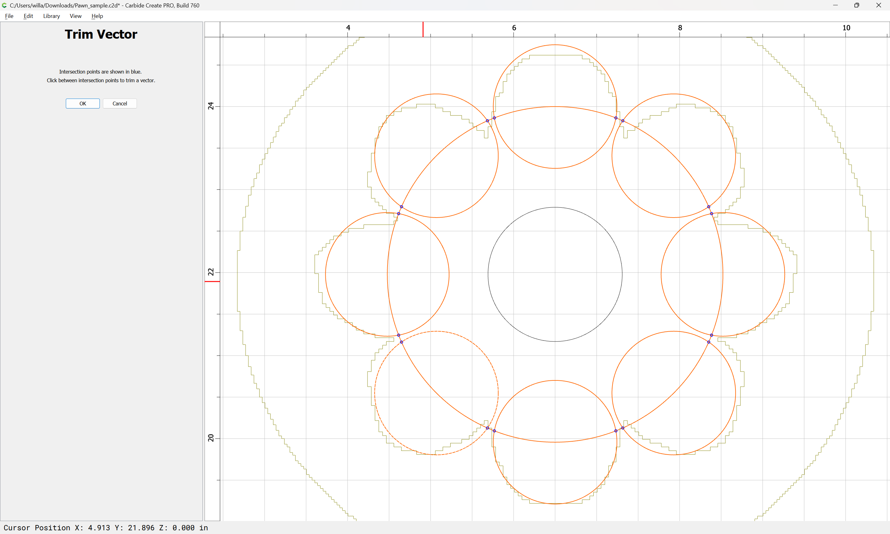
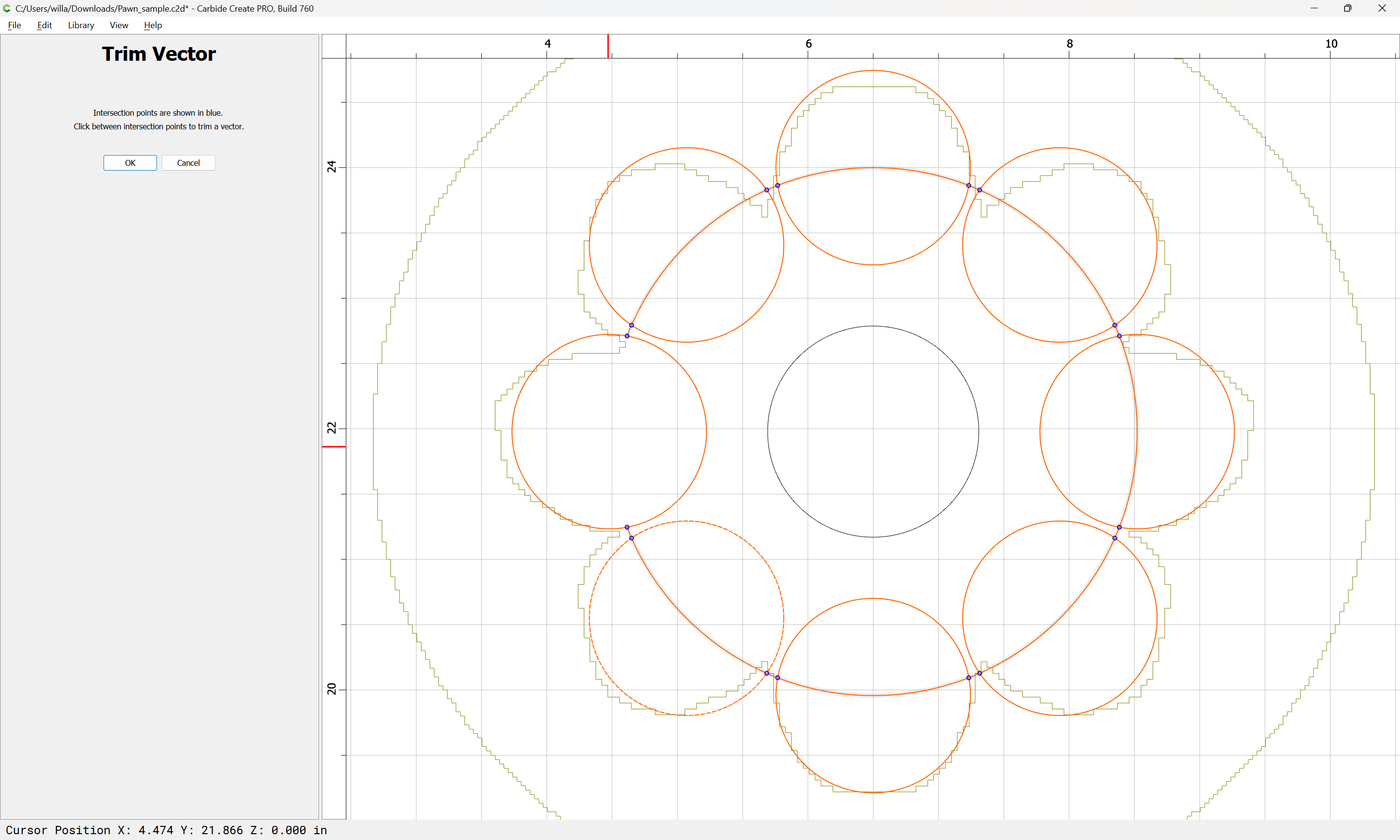
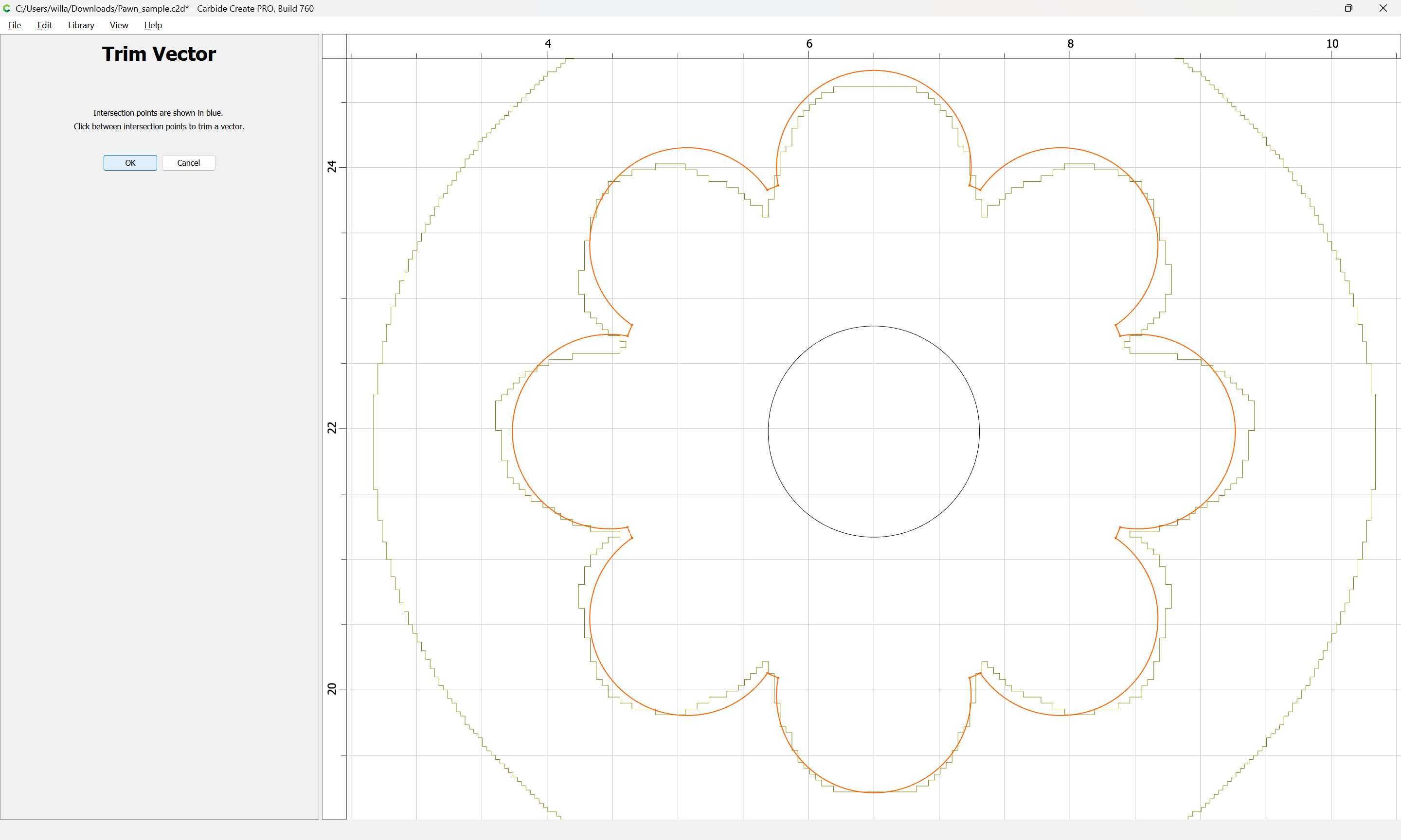
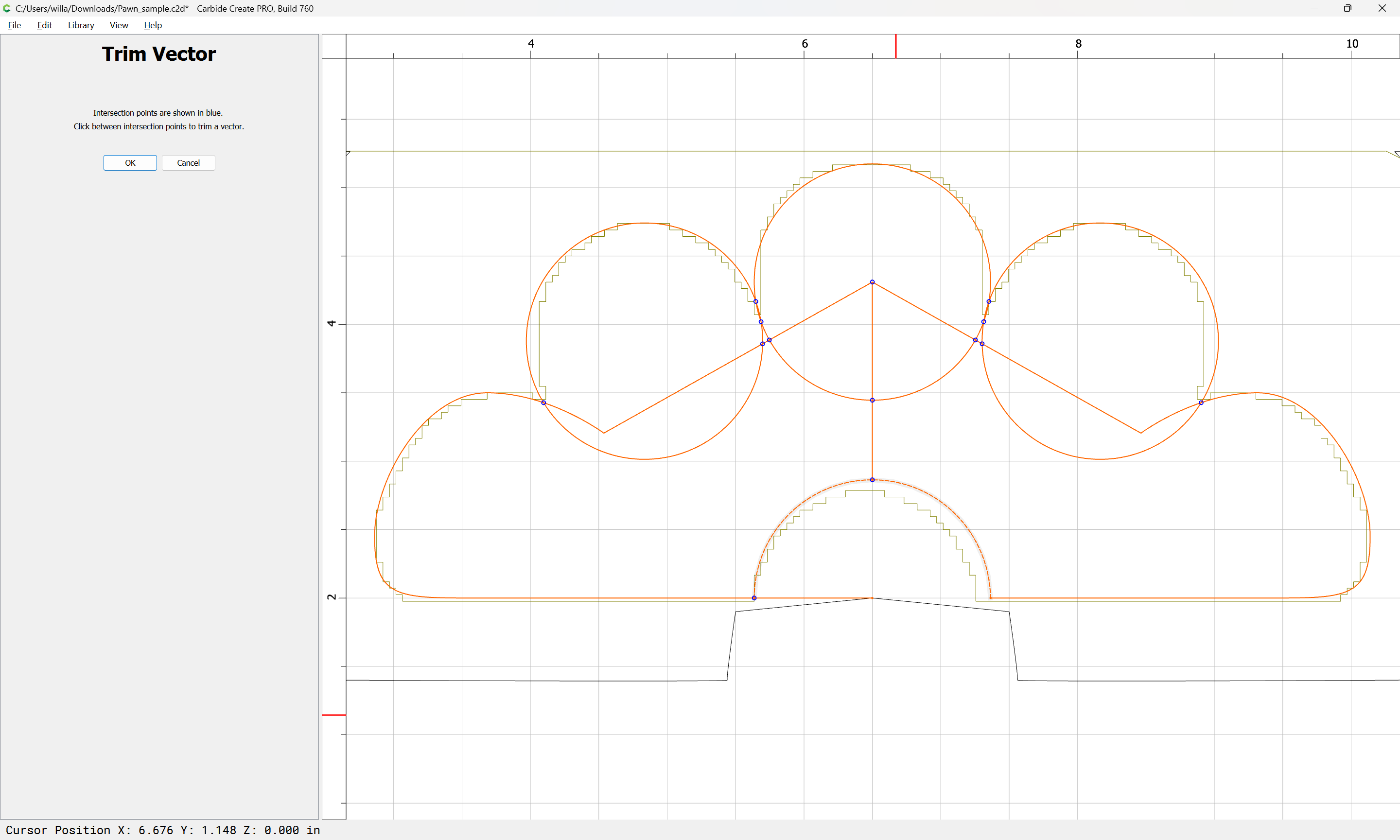
until one arrives at:
OK
OK
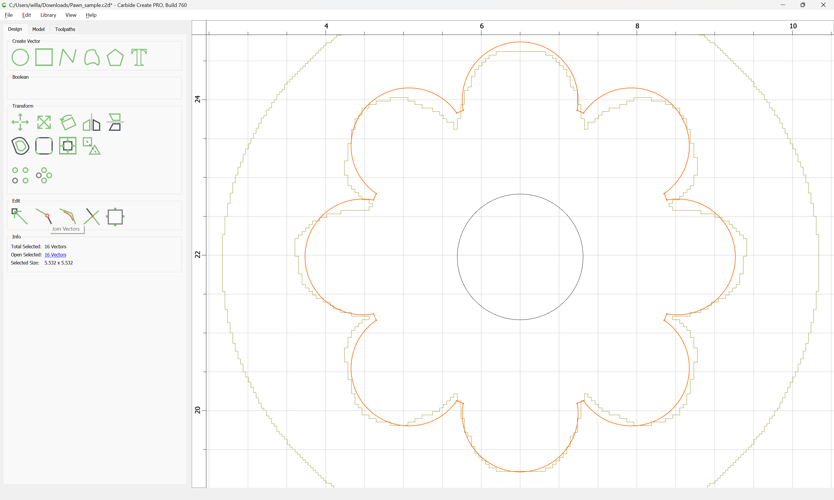
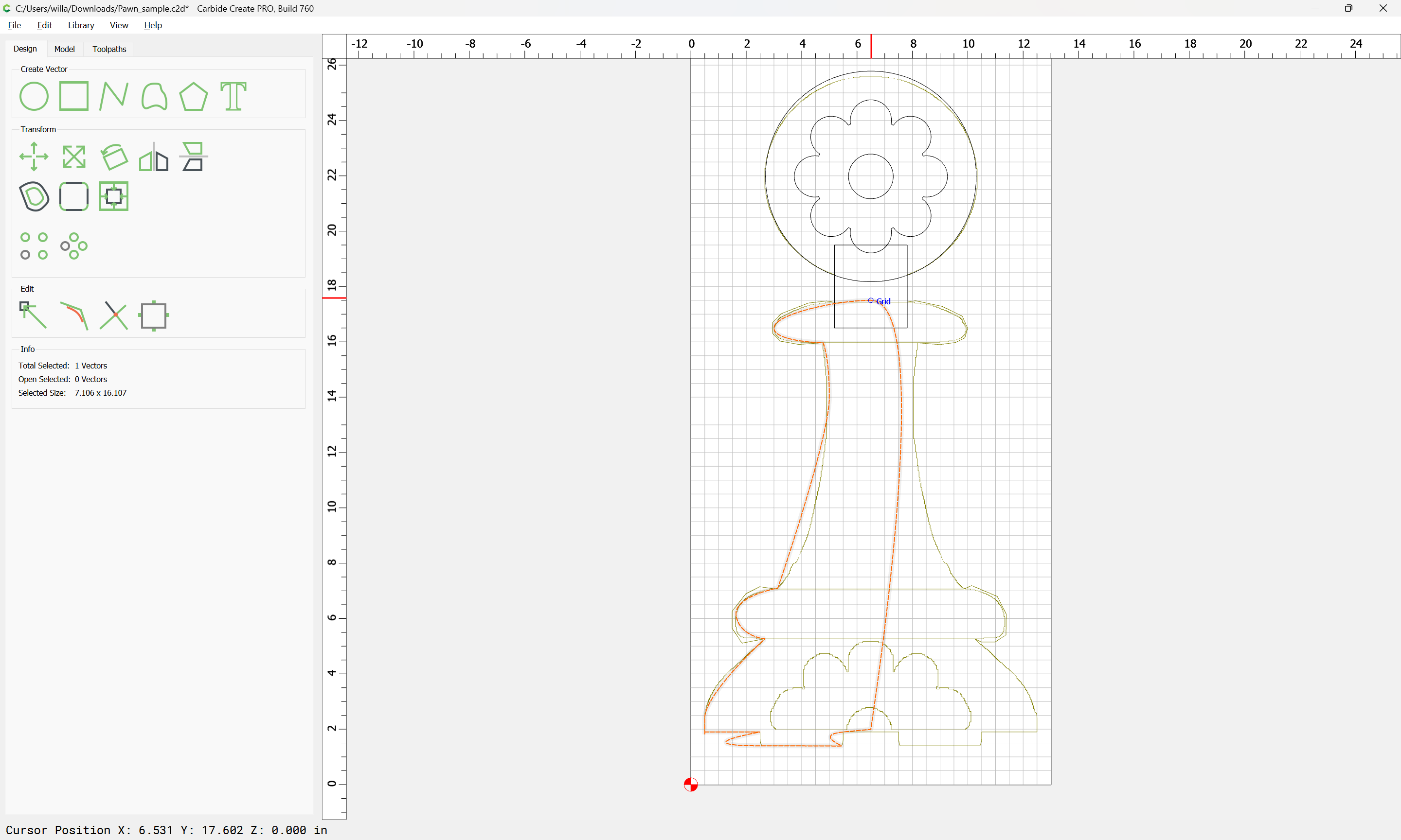
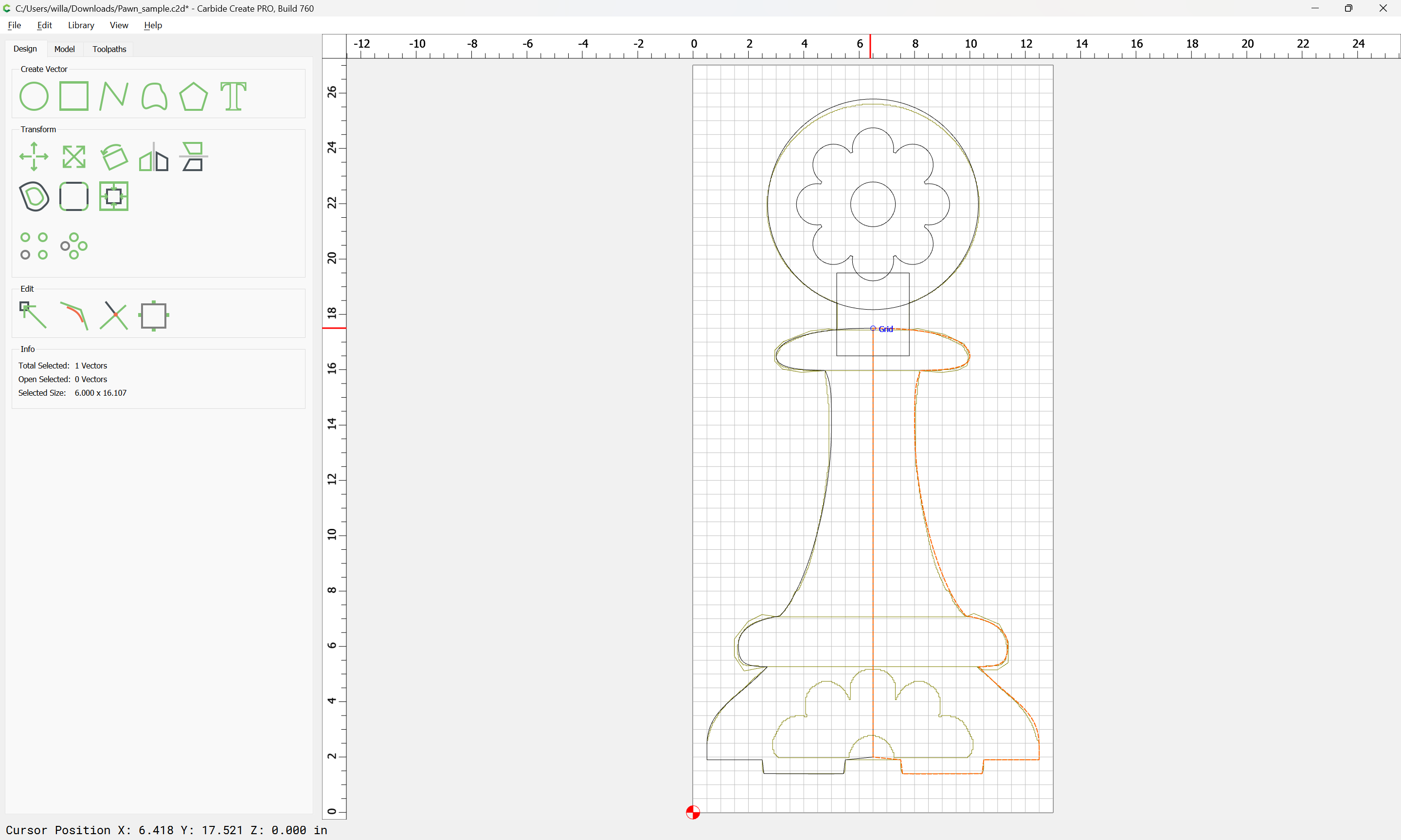
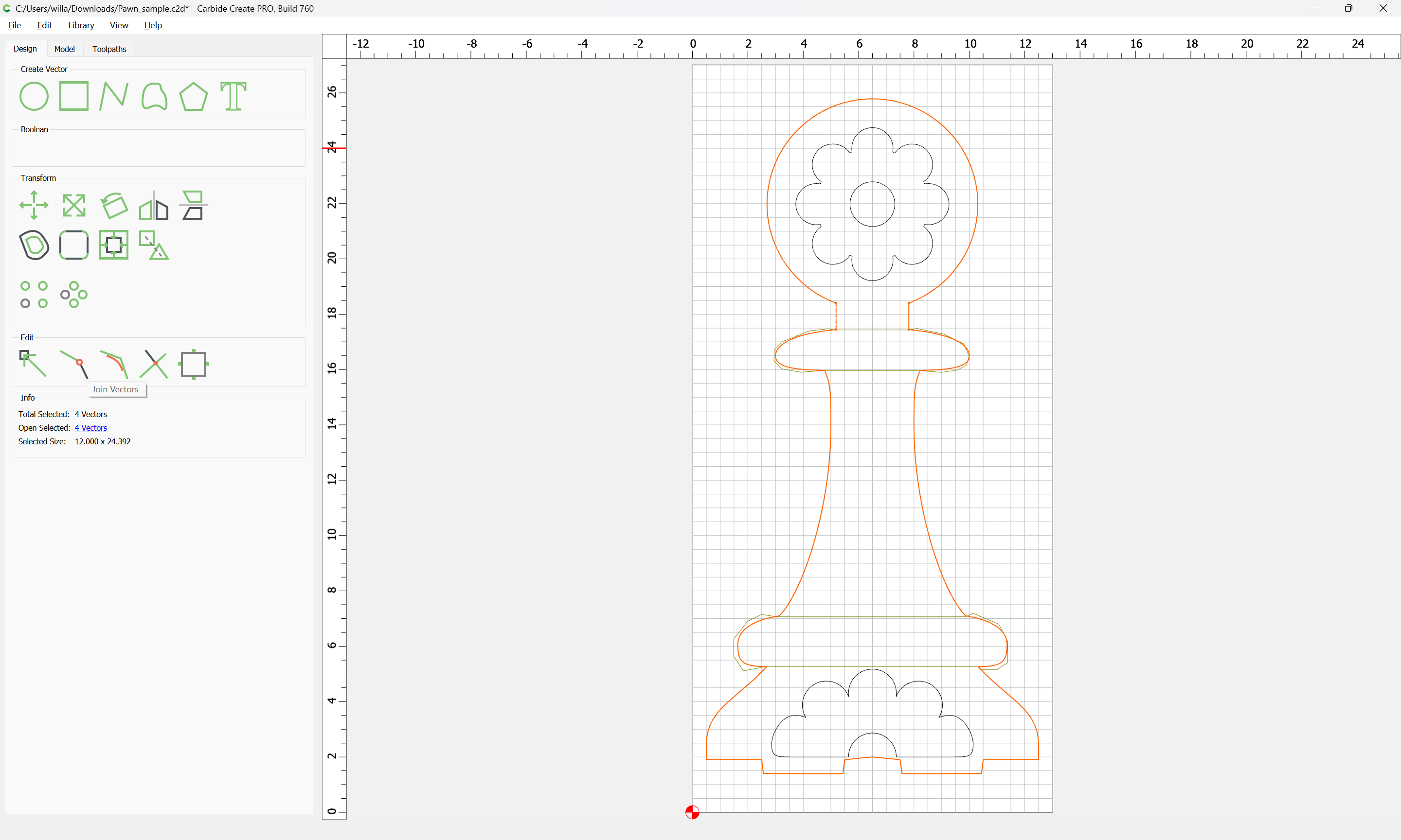
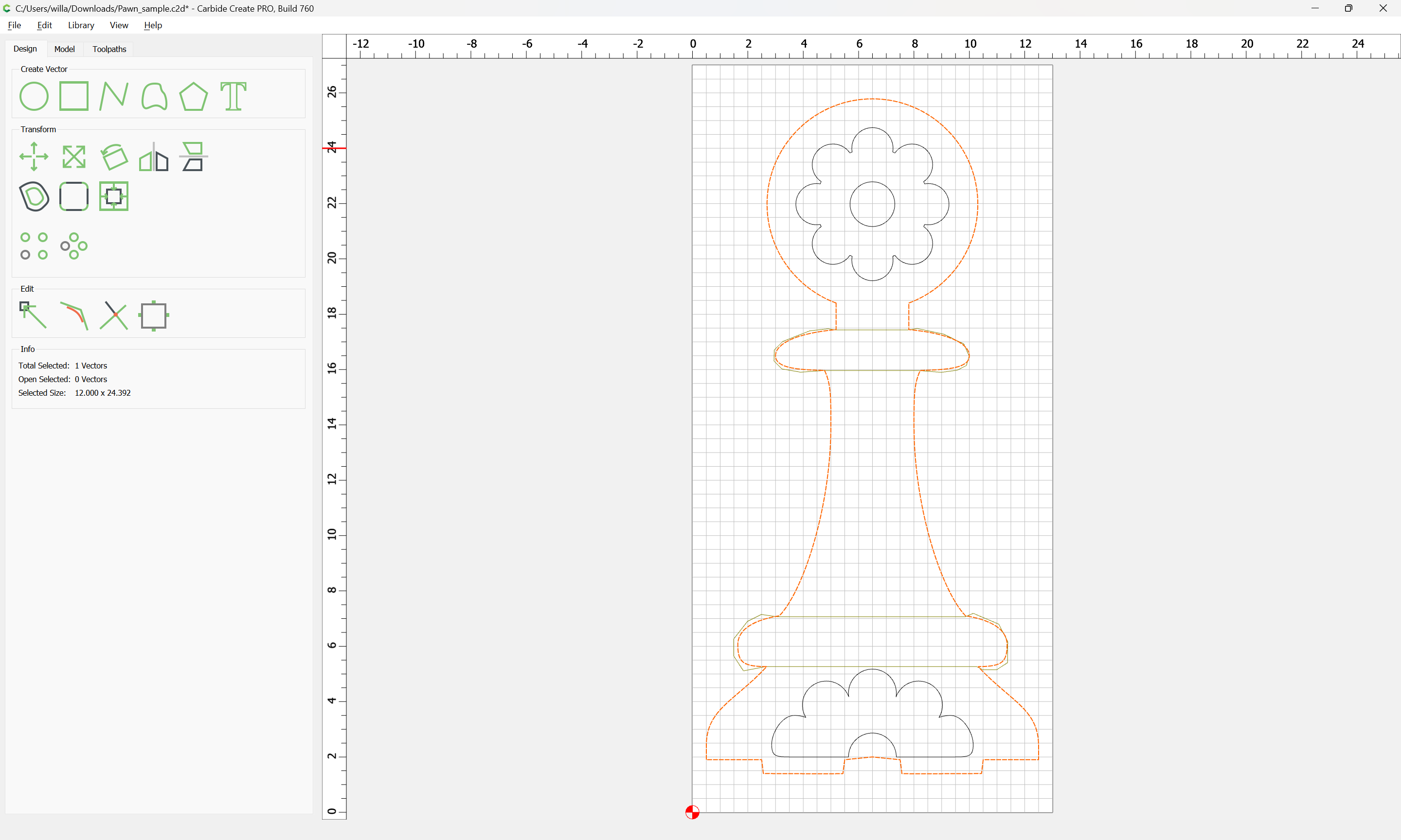
Join Vectors:
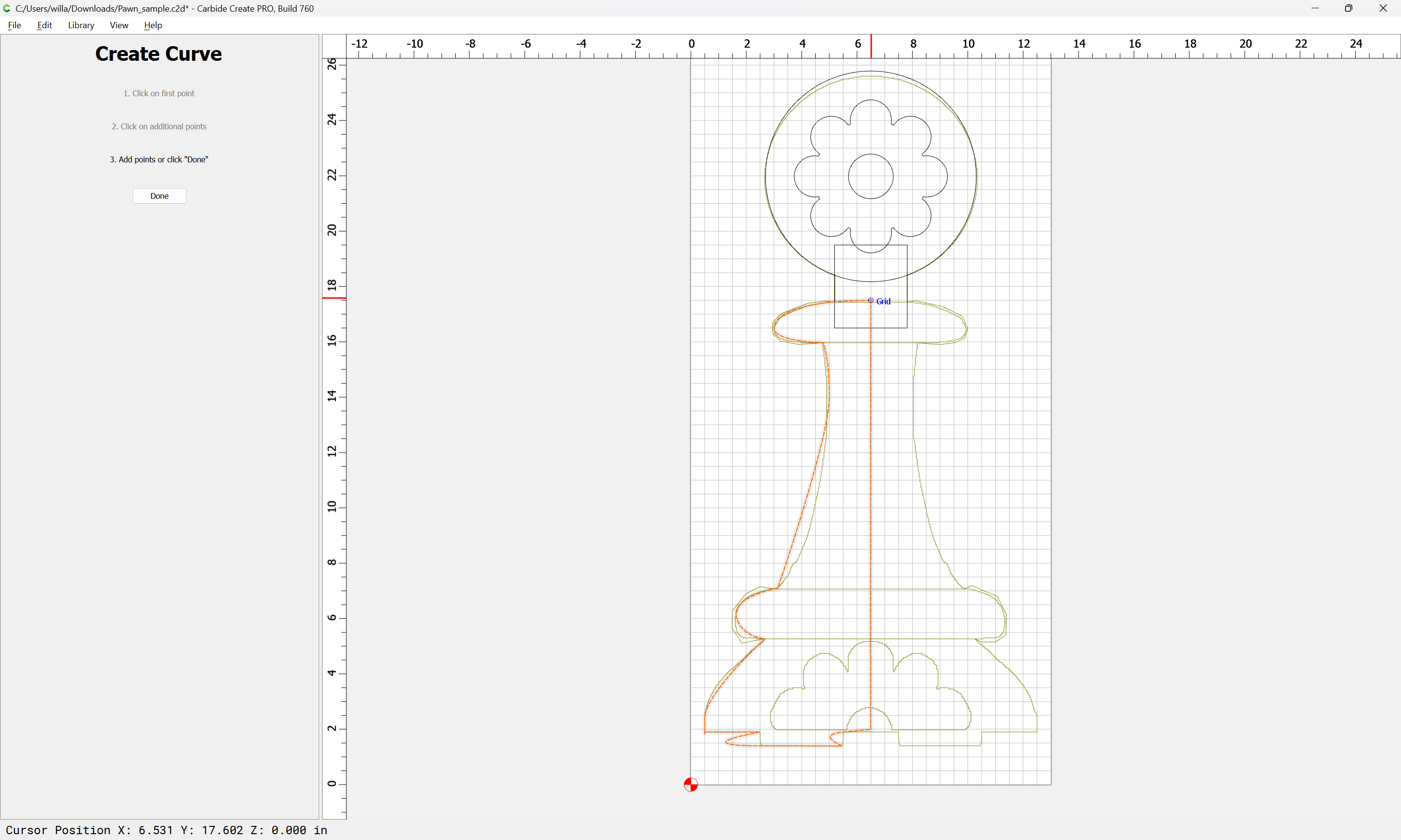
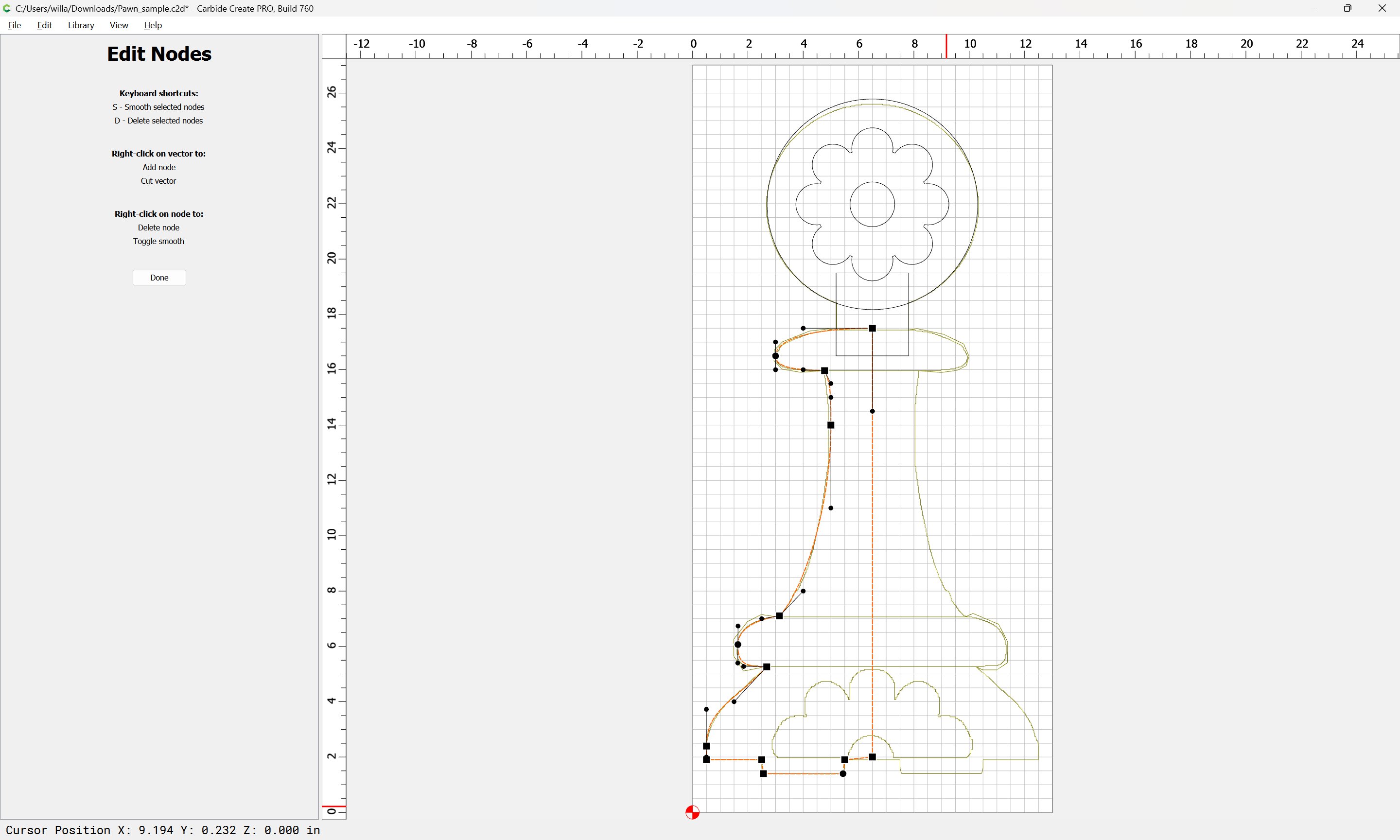
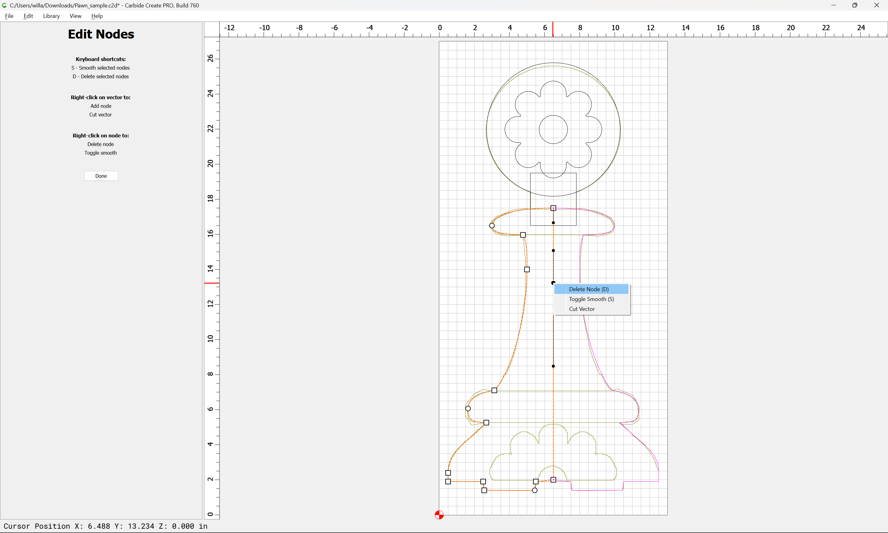
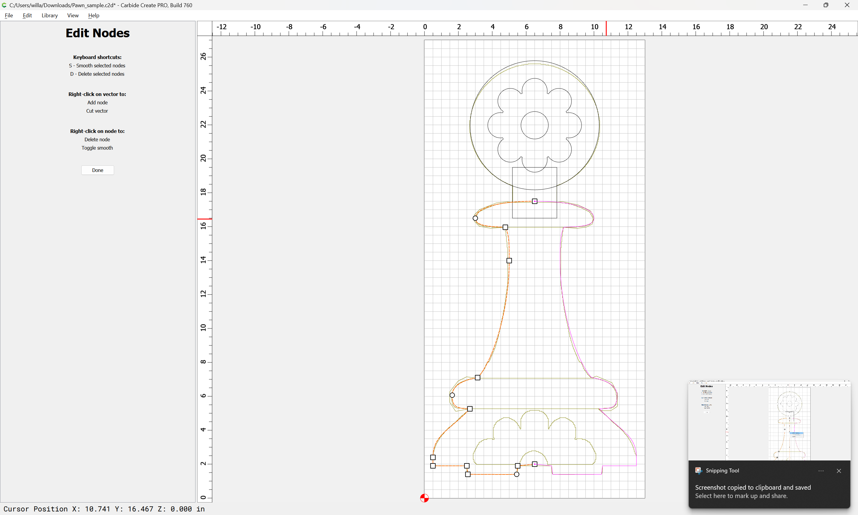
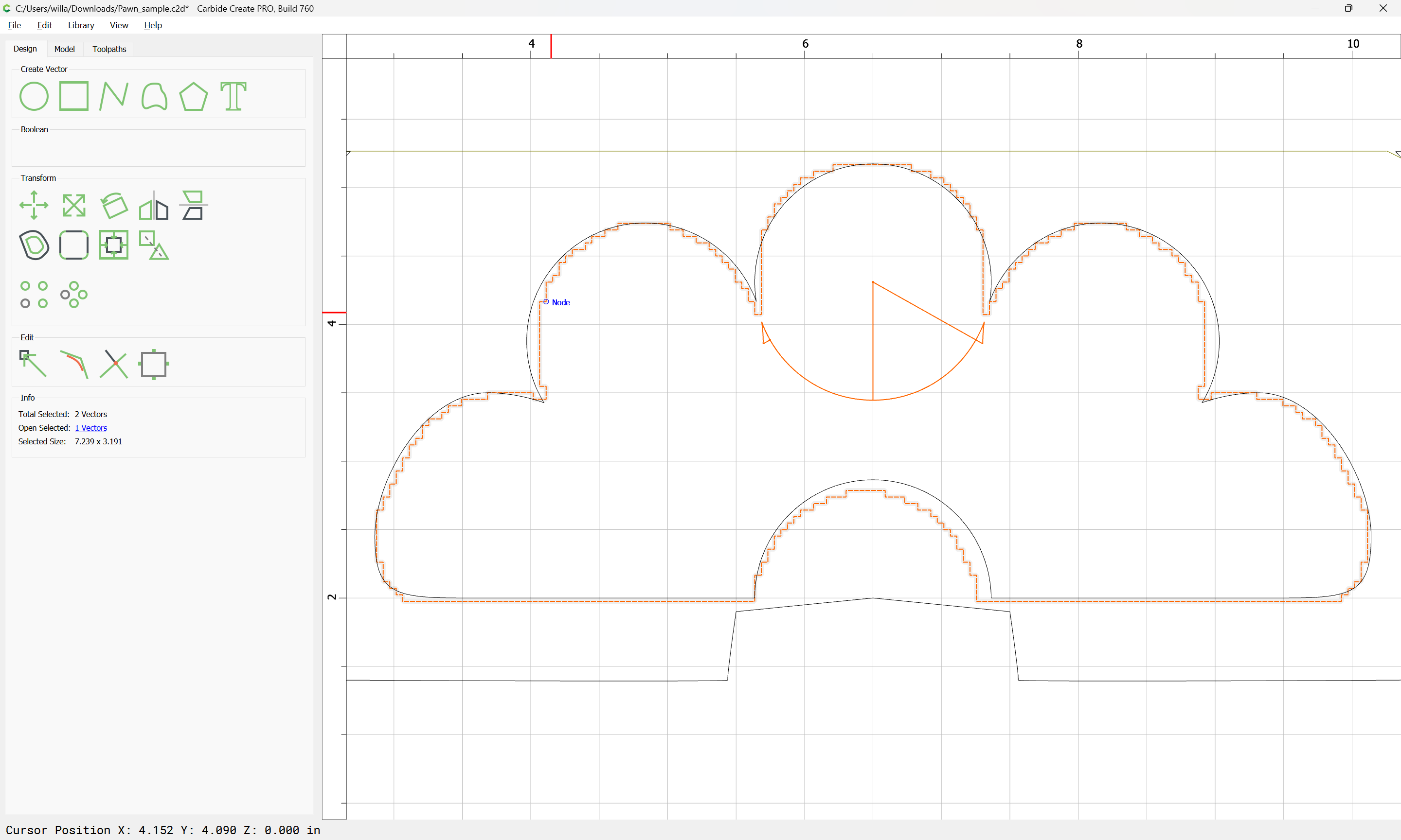
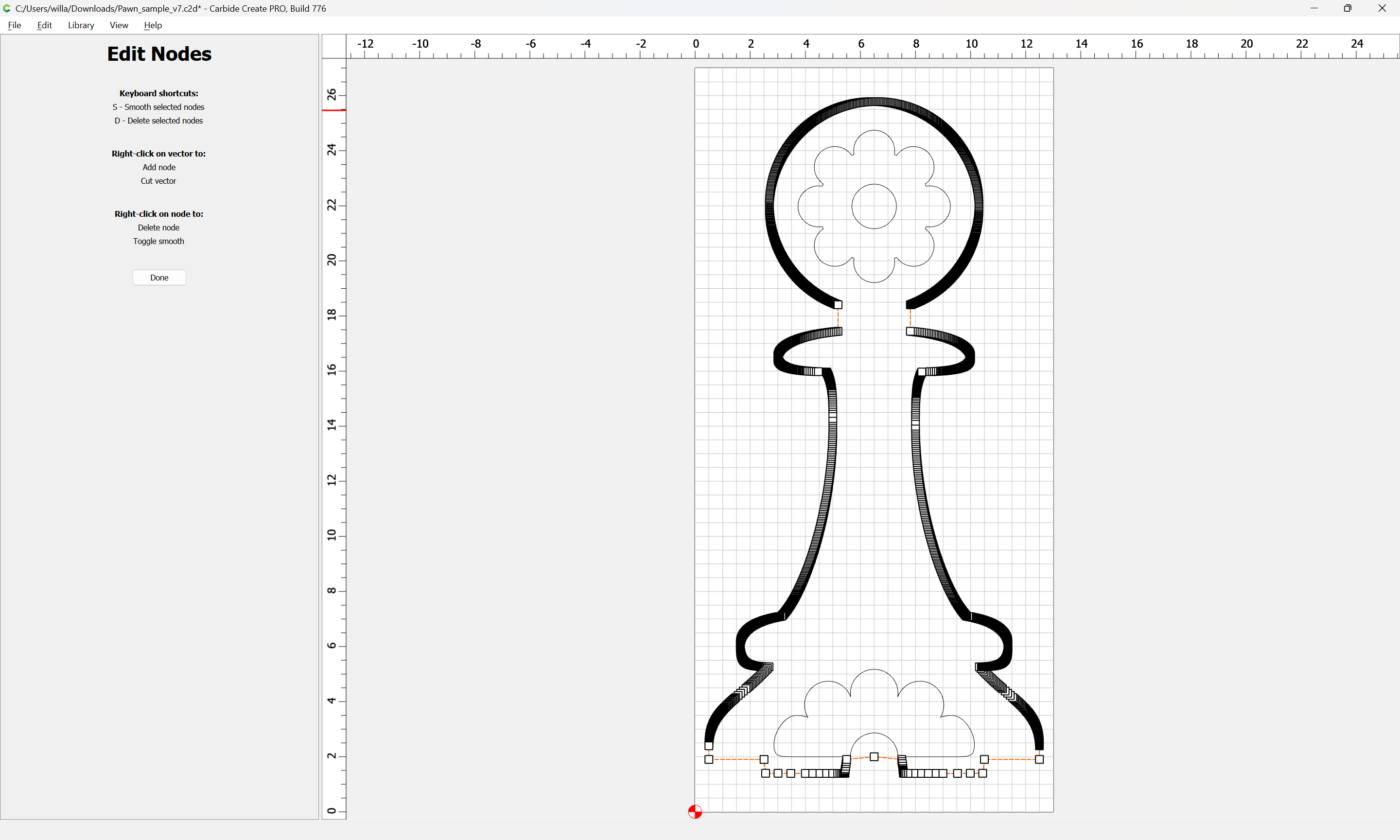
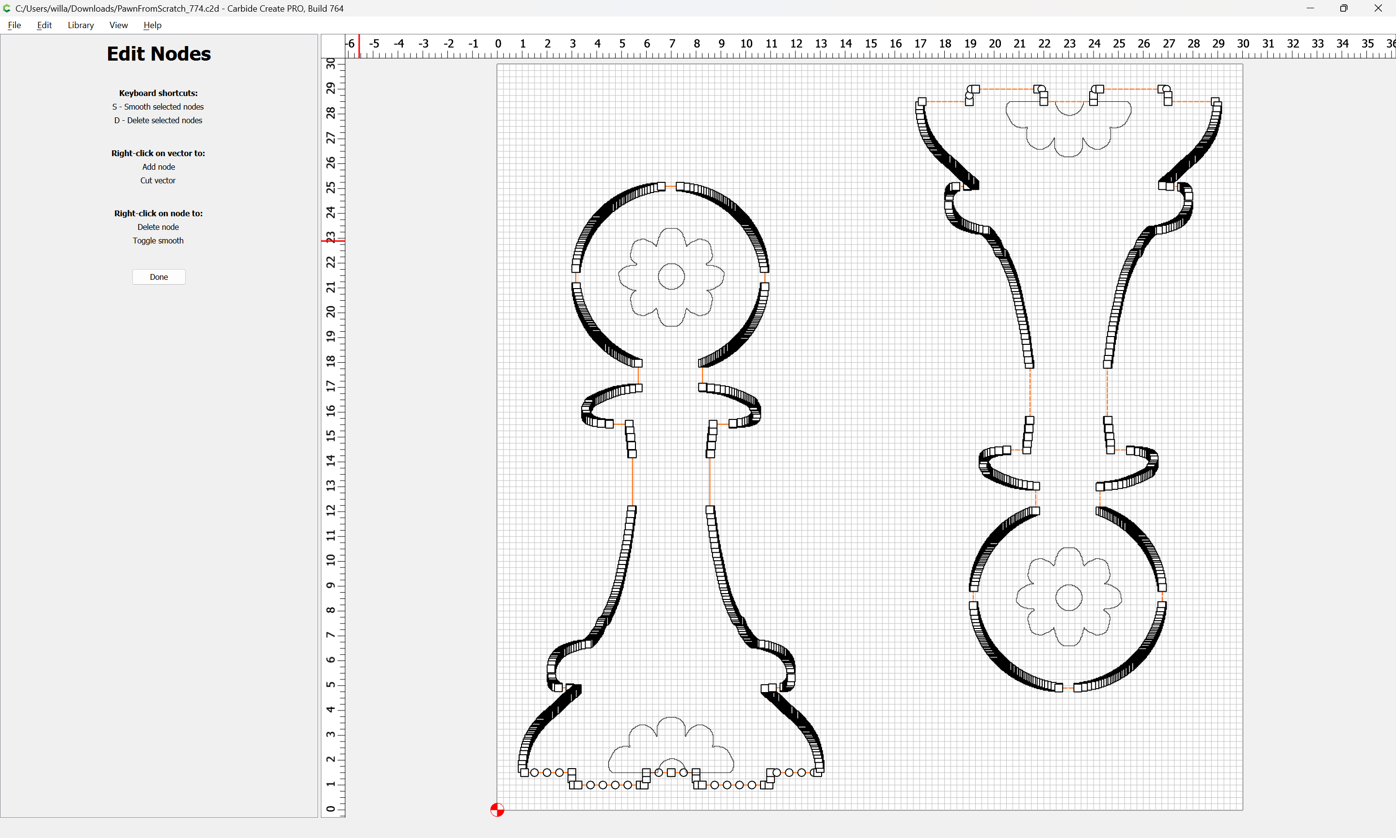
Use Node Editing to adjust as needed:
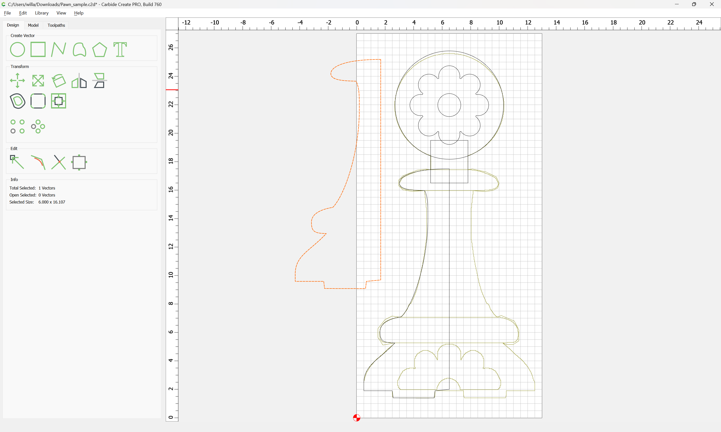
Duplicate and mirror
Edit nodes and remove them to remove unwanted lines:
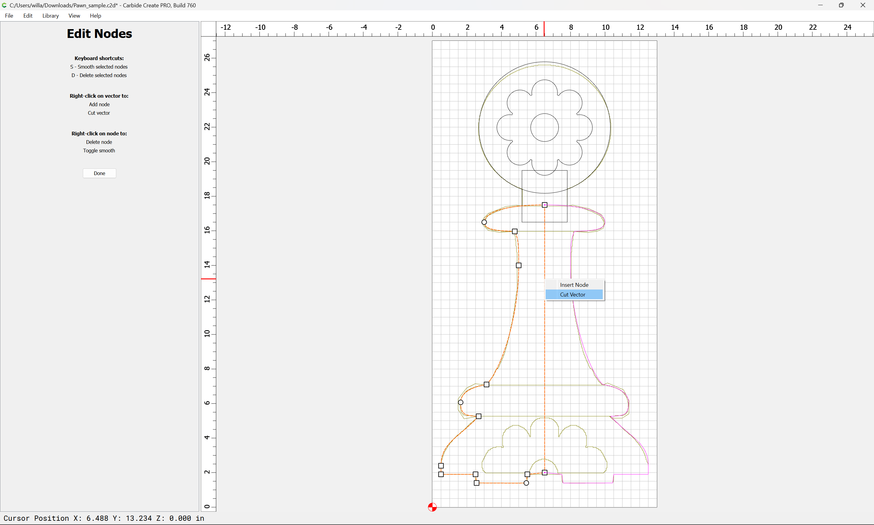
Done
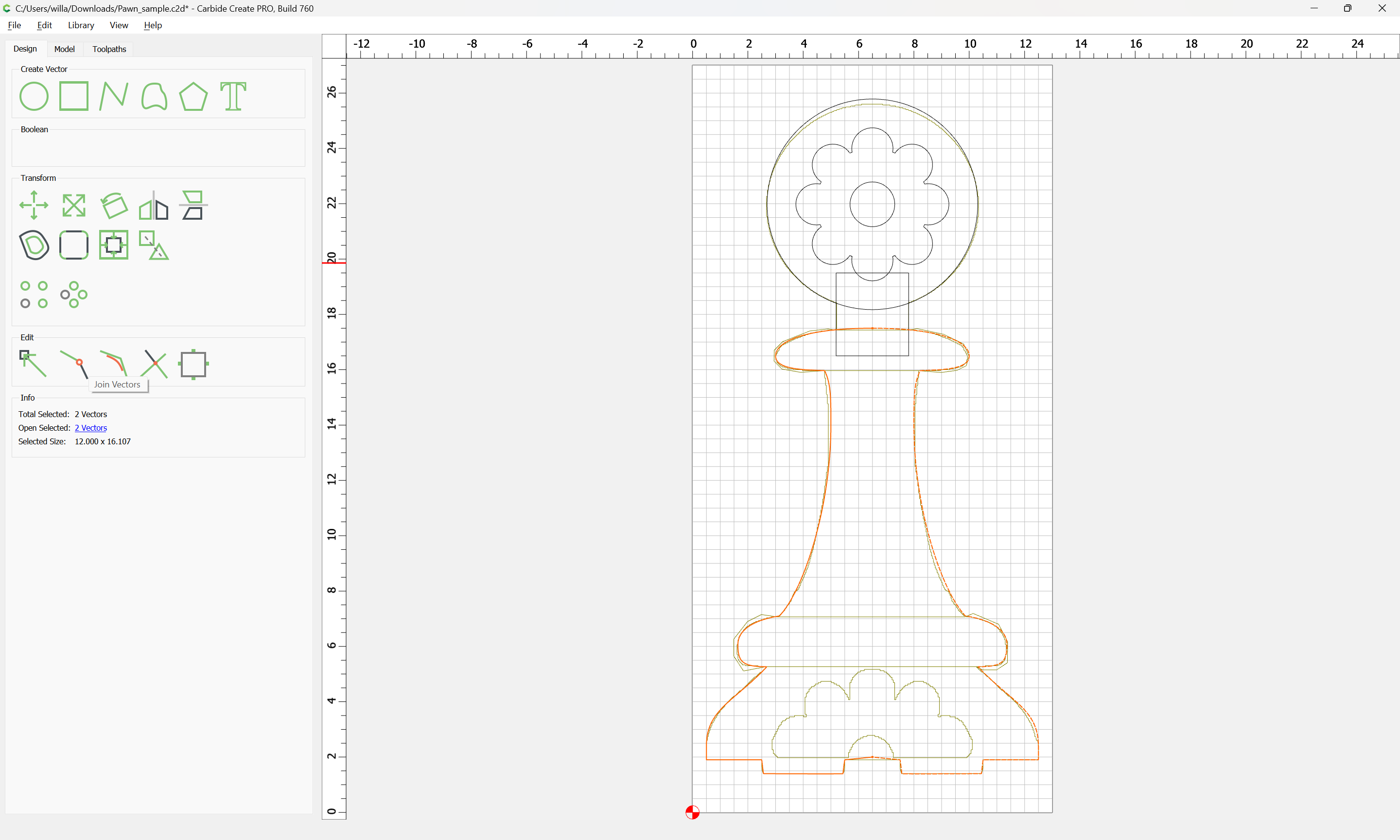
Join Vectors:
and continue re-drawing:
Done
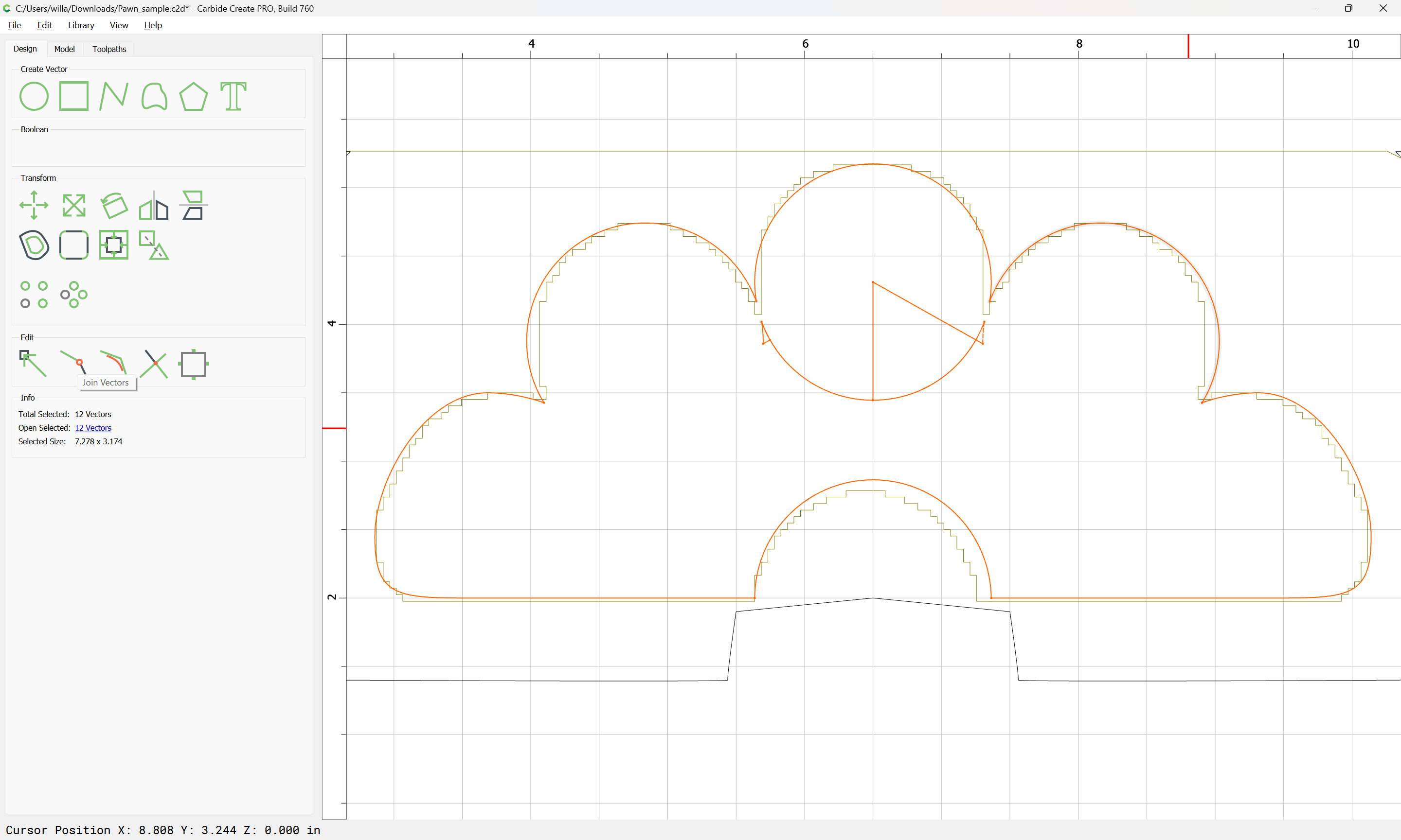
Join Vectors
Delete what is not wanted:
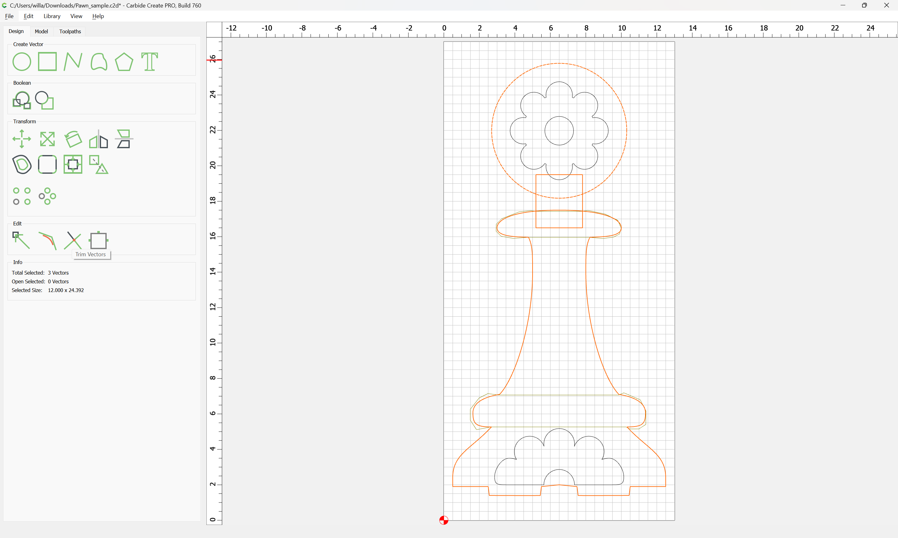
Then use Trim Vectors to fix things:
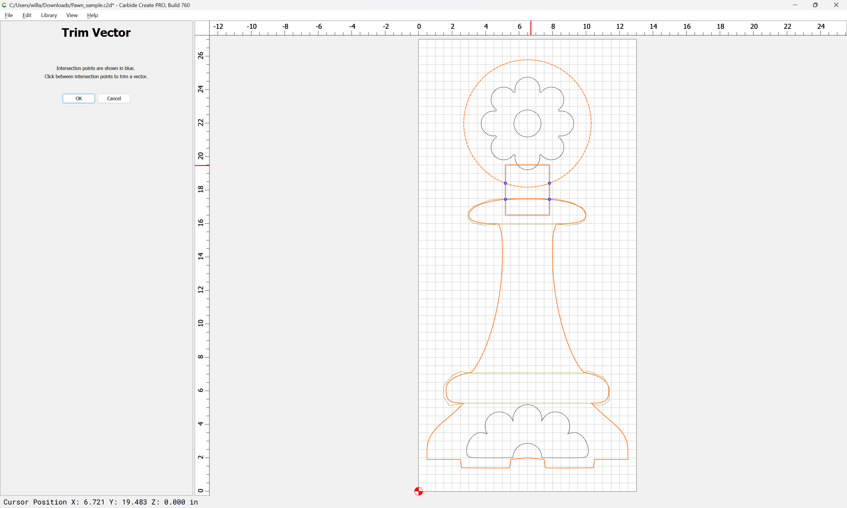

OK
Join Vectors
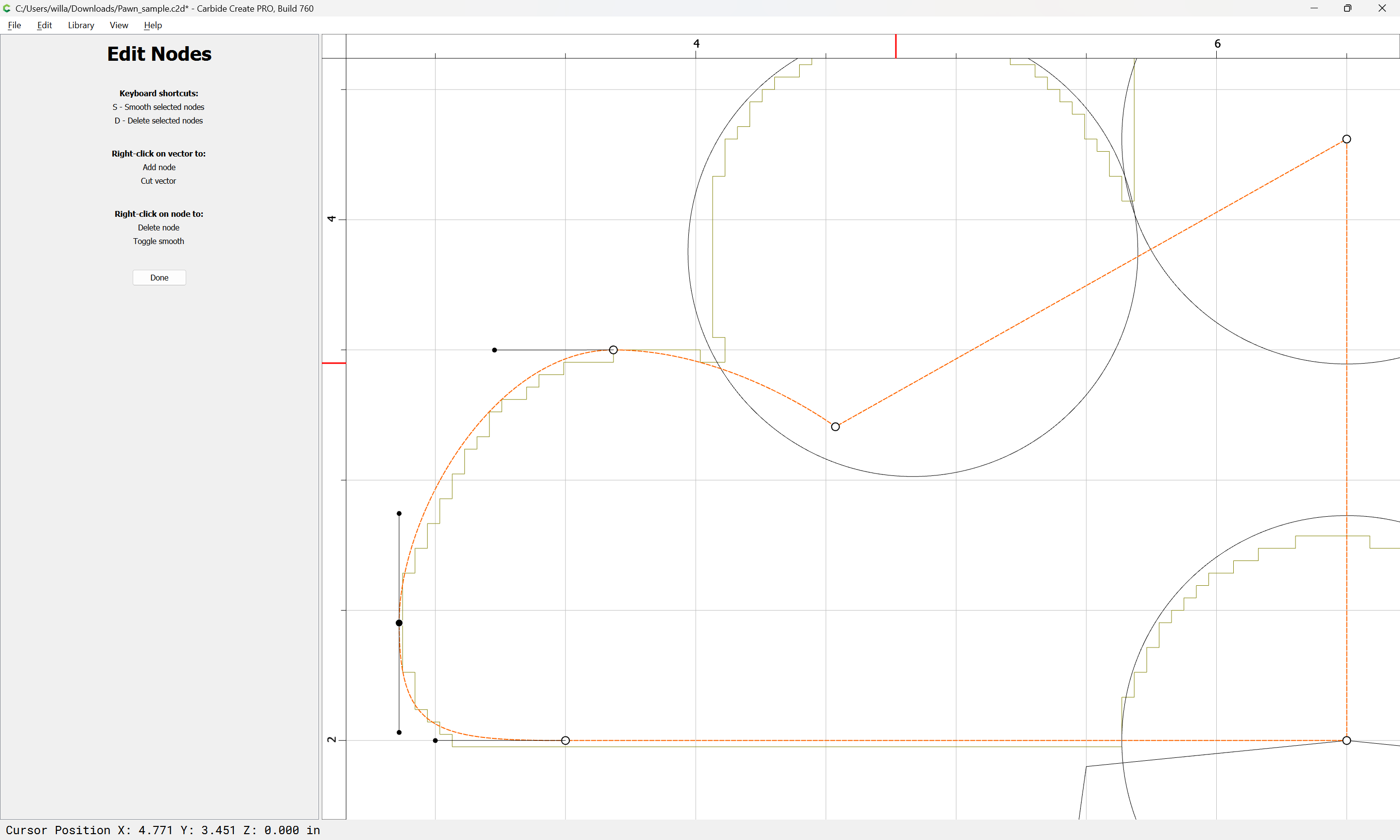
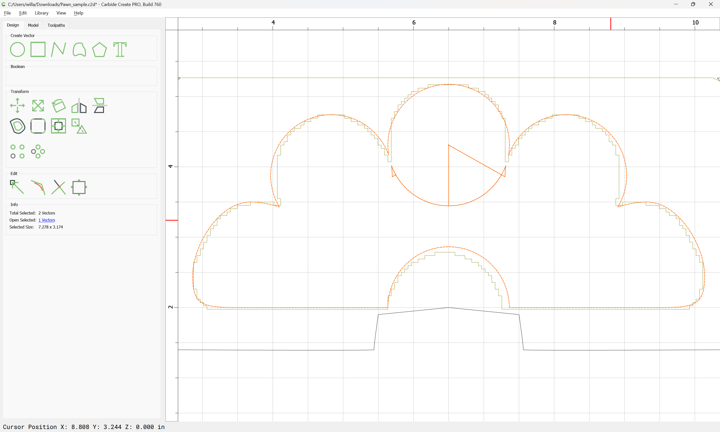
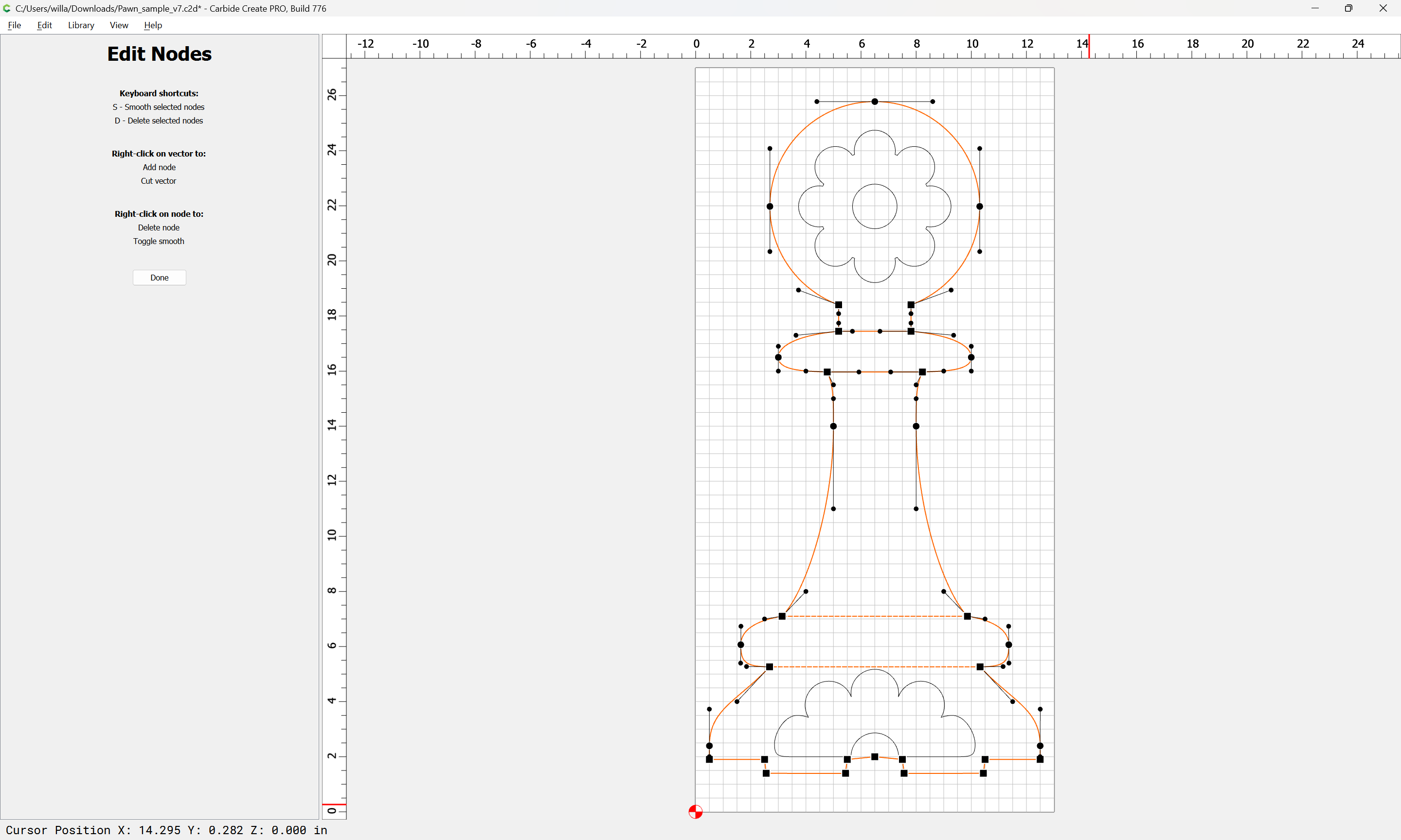
Duplicate the outline and use Node Editing to make the crossing geometry:
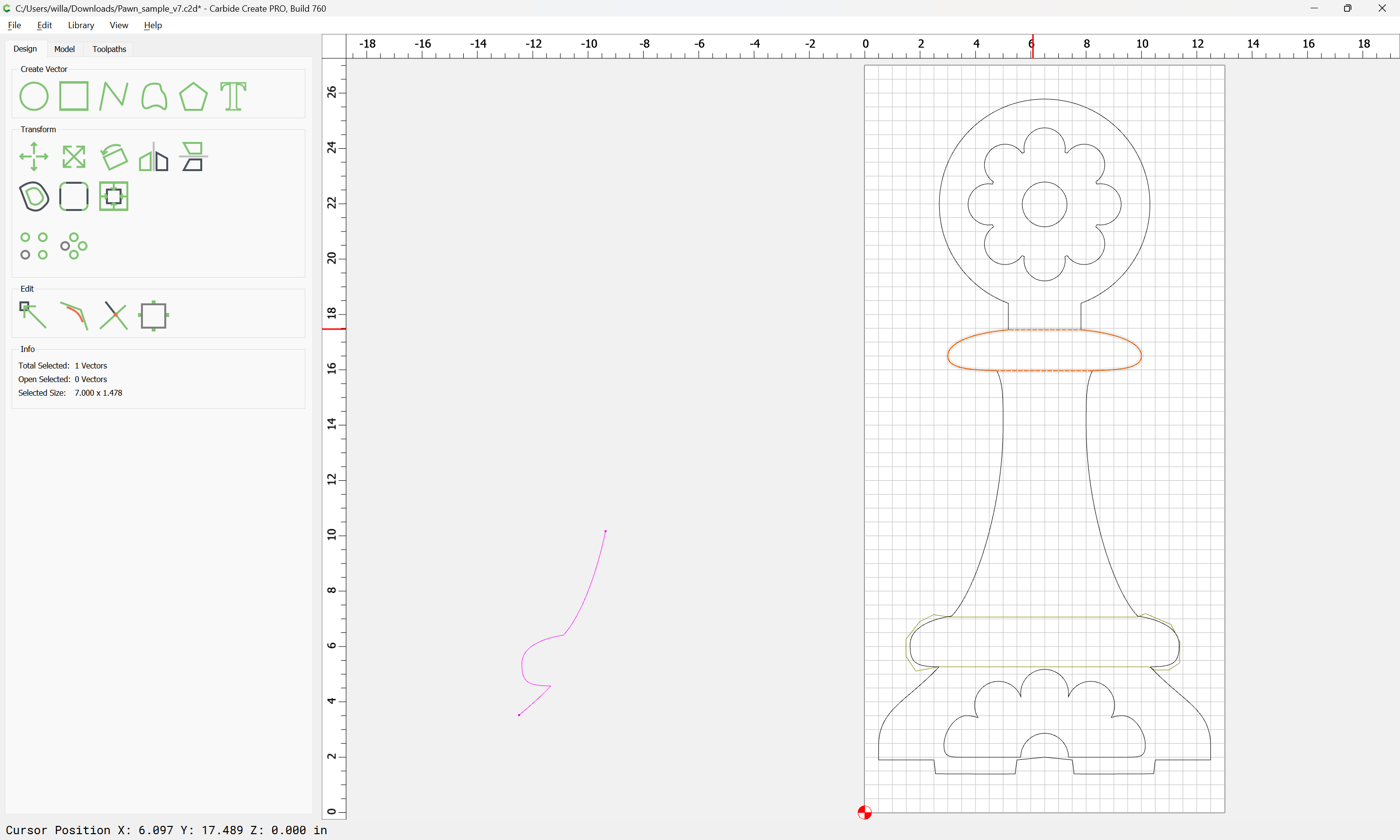
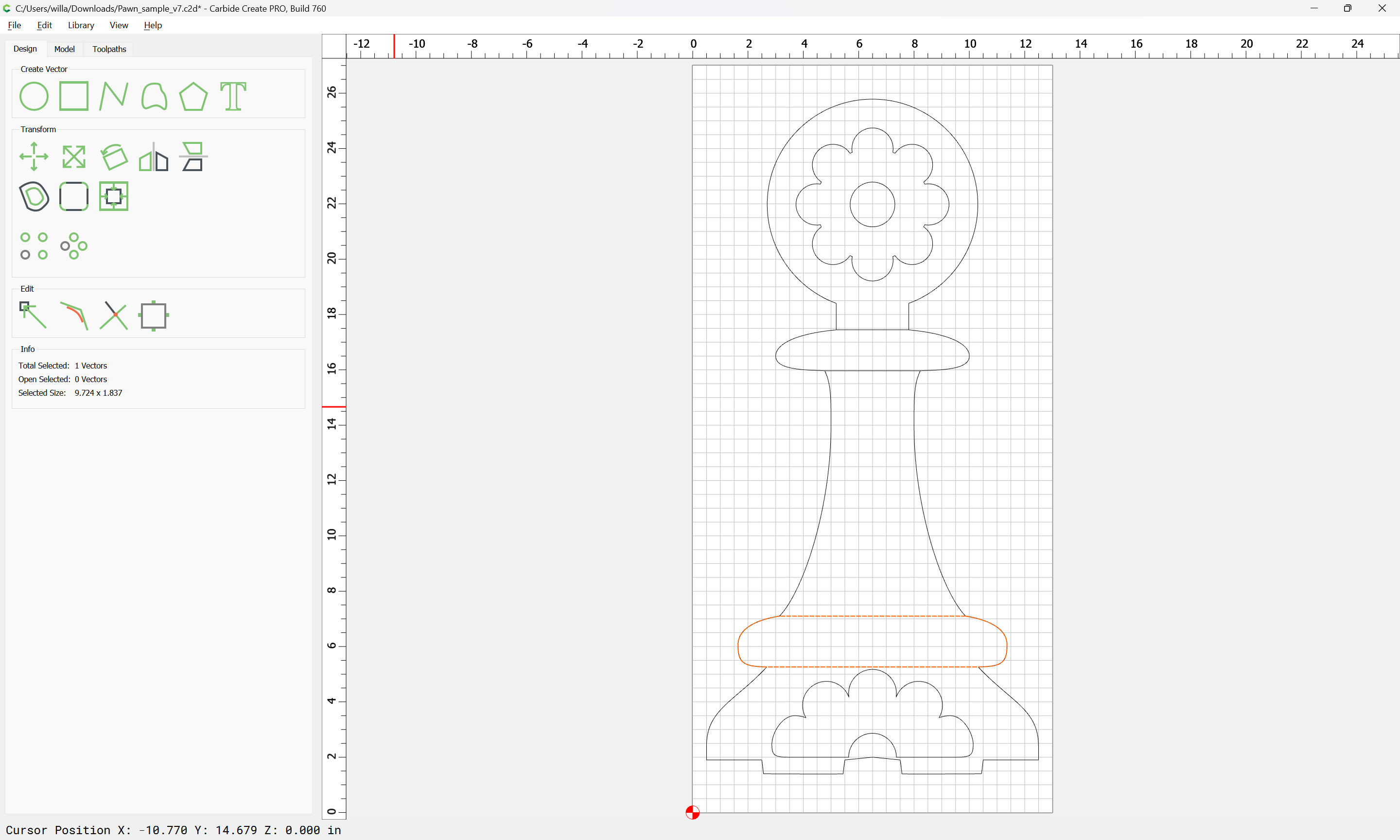
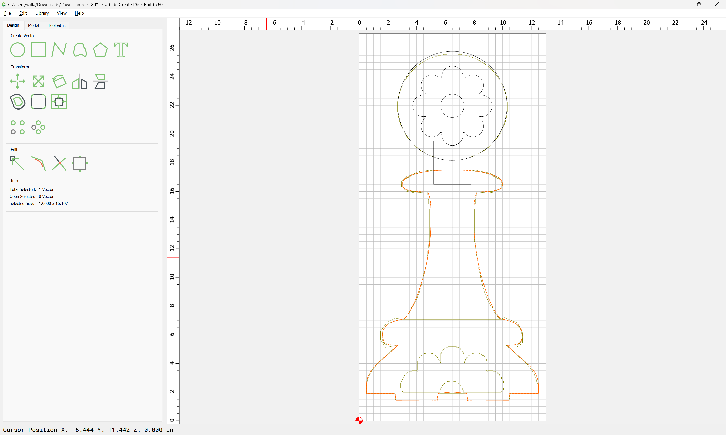
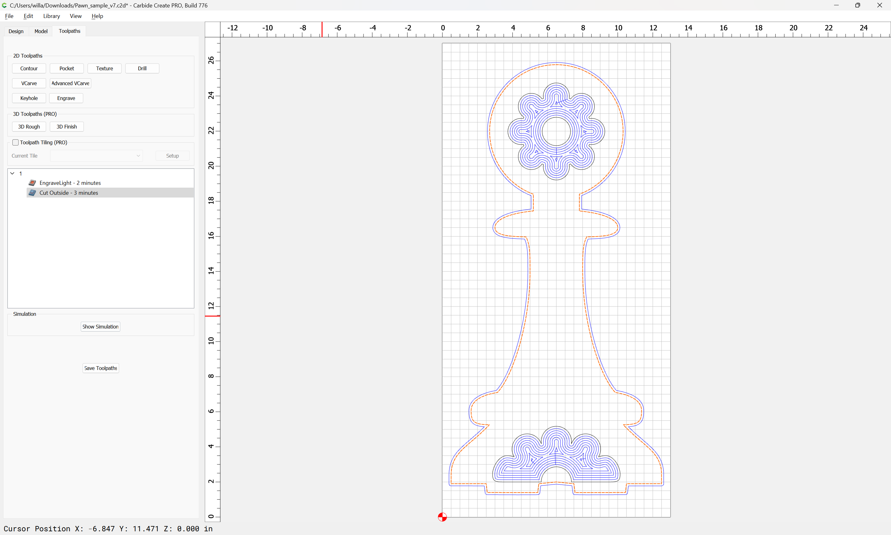
The re-drawn geometry works in 760:
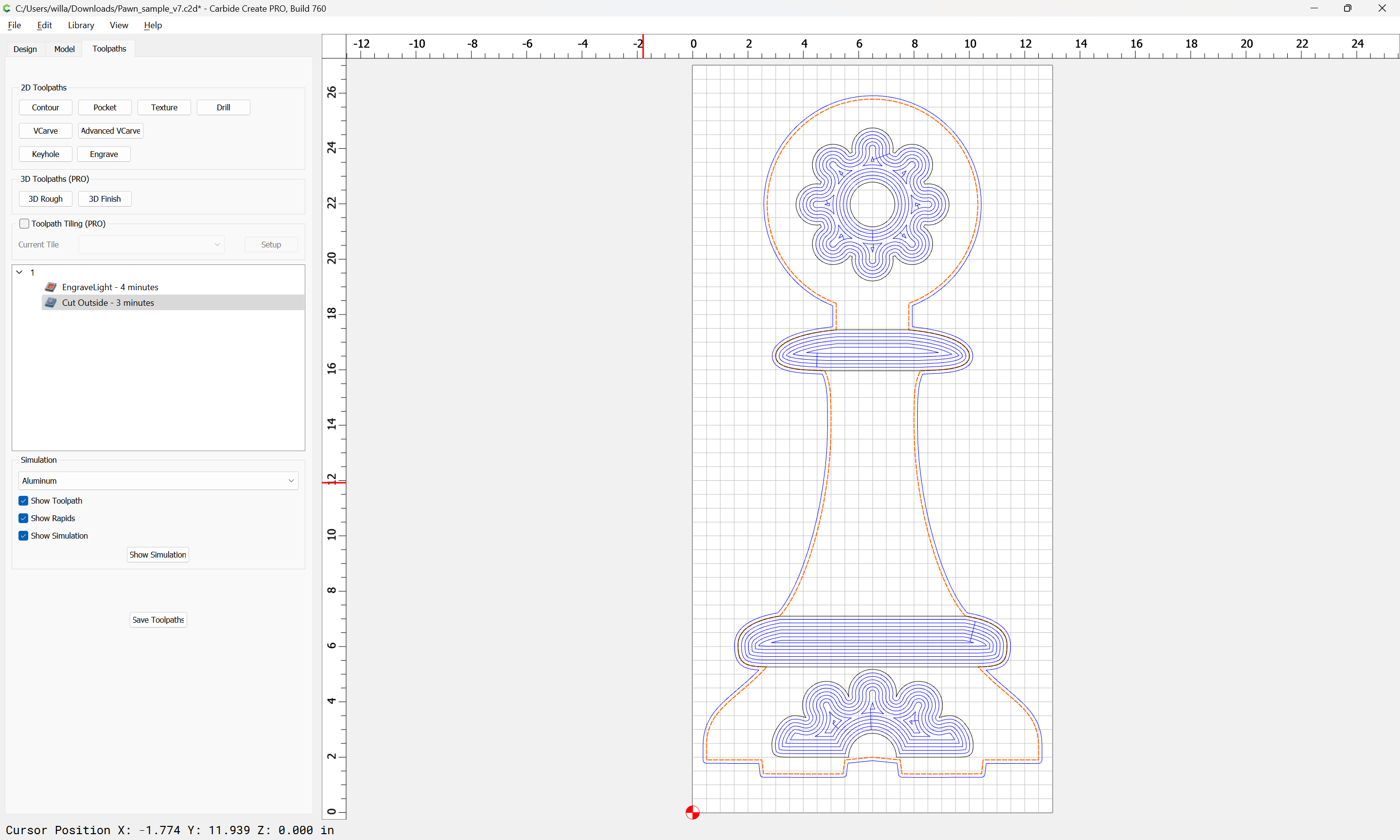
and in 776:
Attached as a v7 file:
Pawn_sample_v7.c2d (152 KB)
1 Like
Note that changing into a polyline:
still yields a working toolpath:
by way of contrast with the previous curvilinear representation:
I appreciate all the work and I think it gives me a way forward on fixing the other pieces.
In case it helps anyone else, I think a large part of the issue is that I’m starting from svg files that I import into Carbide Create.
These are the 2 source files for the pawn and they were drawn in Krita:


So my workflow is:
import them
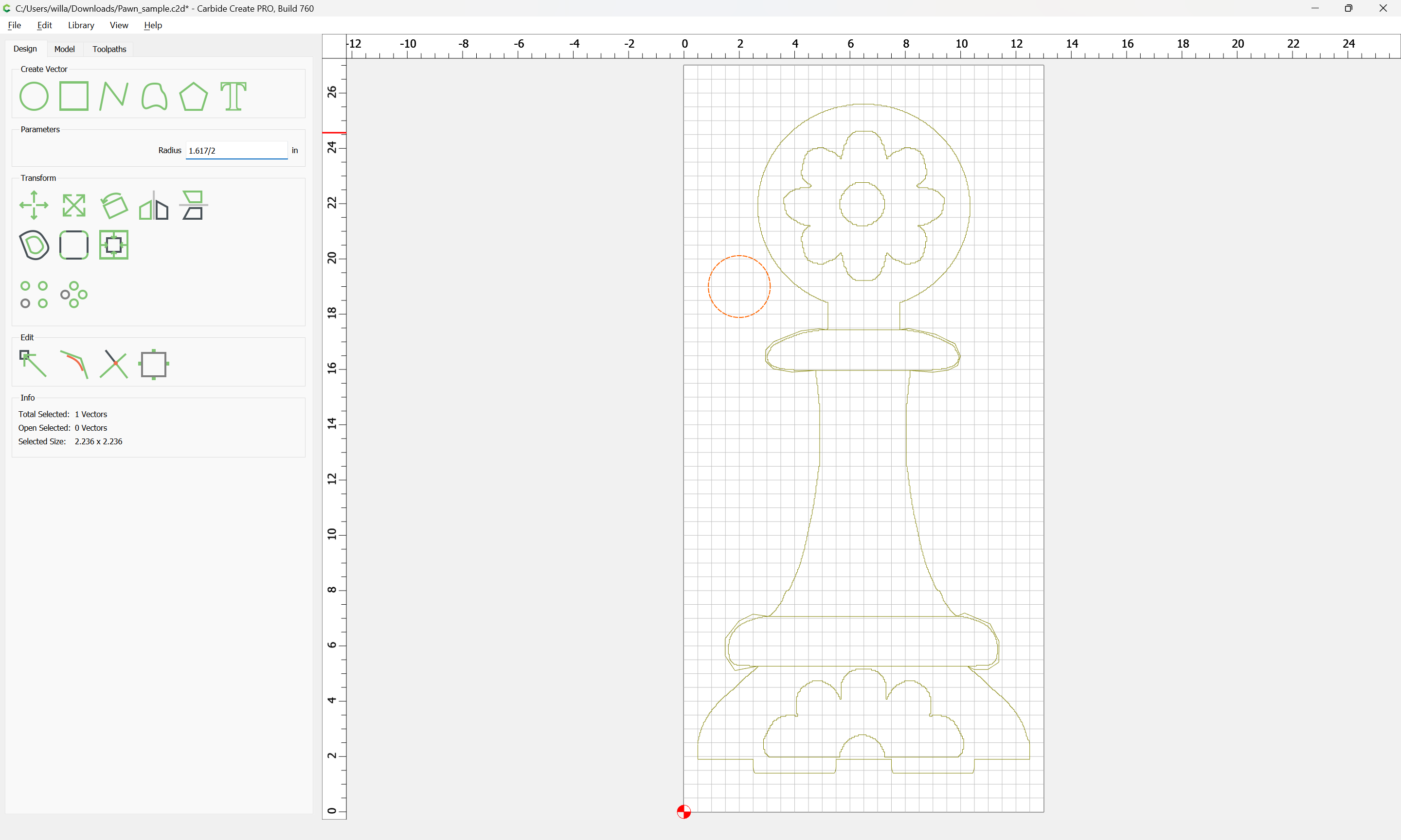
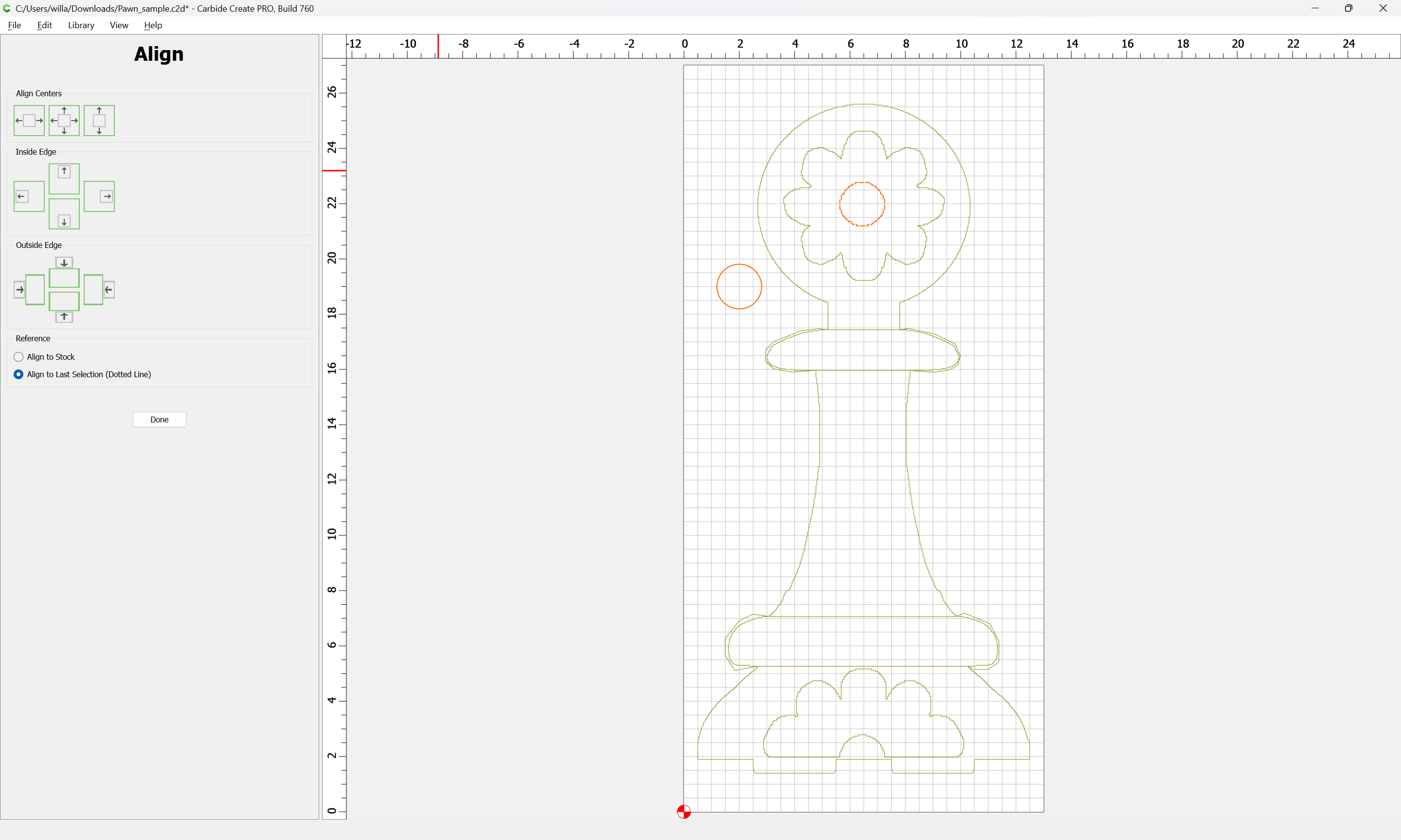
align them and remove the inner “shadow line” from Pawn_Cut.svg
scale them up so the base is 12 in - so a 9.942 scale factor
Clean up the bottom of the piece by deleting extra nodes.
add the “teeth” on the bottom that will glue into the base by inserting nodes
Add the toolpath for the outside cut
Rotate a copy so that I can get 2 on a sheet
When I just did all of that this morning… I still get the problem, like this
Here’s the current version of that file
PawnFromScratch_774.c2d (312 KB)
I’ve got a bunch of things to do today, but I’ll spend some time tonight replacing nodes on the bottom curve with splines like you did.
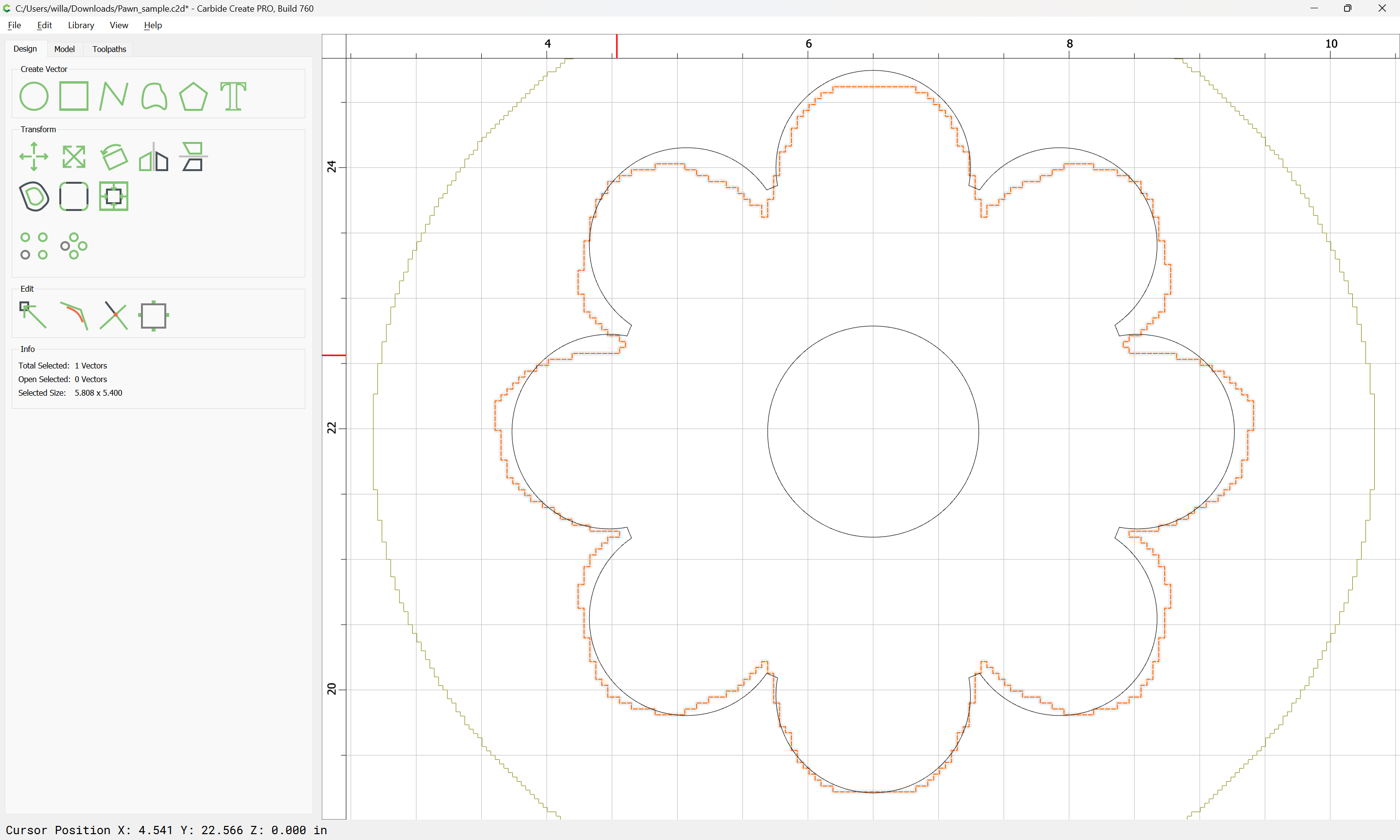
Still a bunch of nodes there:
(when possible, it’s best to use Trim Vectors rather than Boolean operations as was shown above).
Once re-drawn with a reasonable number of nodes as a Curve object:
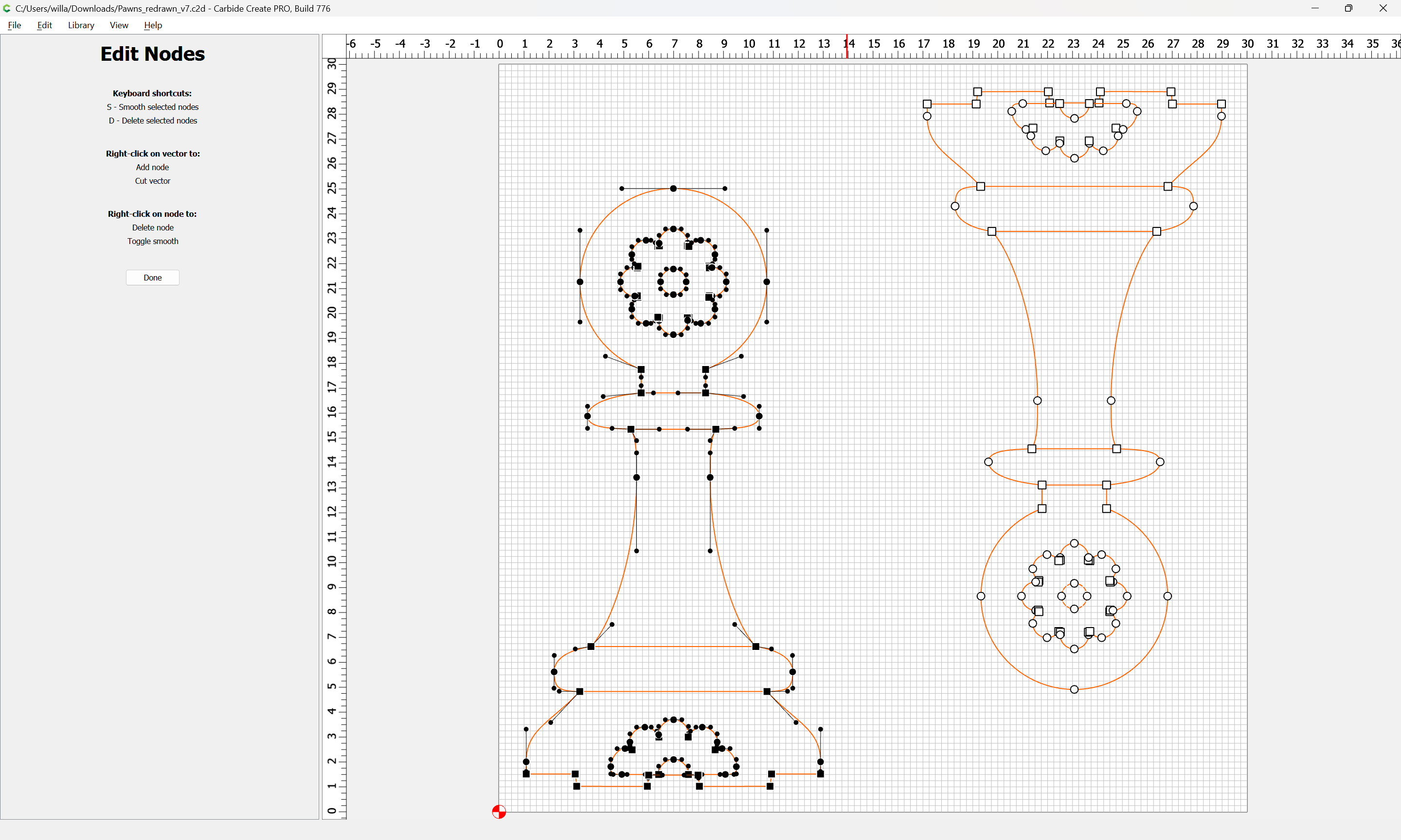
Toolpaths work as expected in the current version:
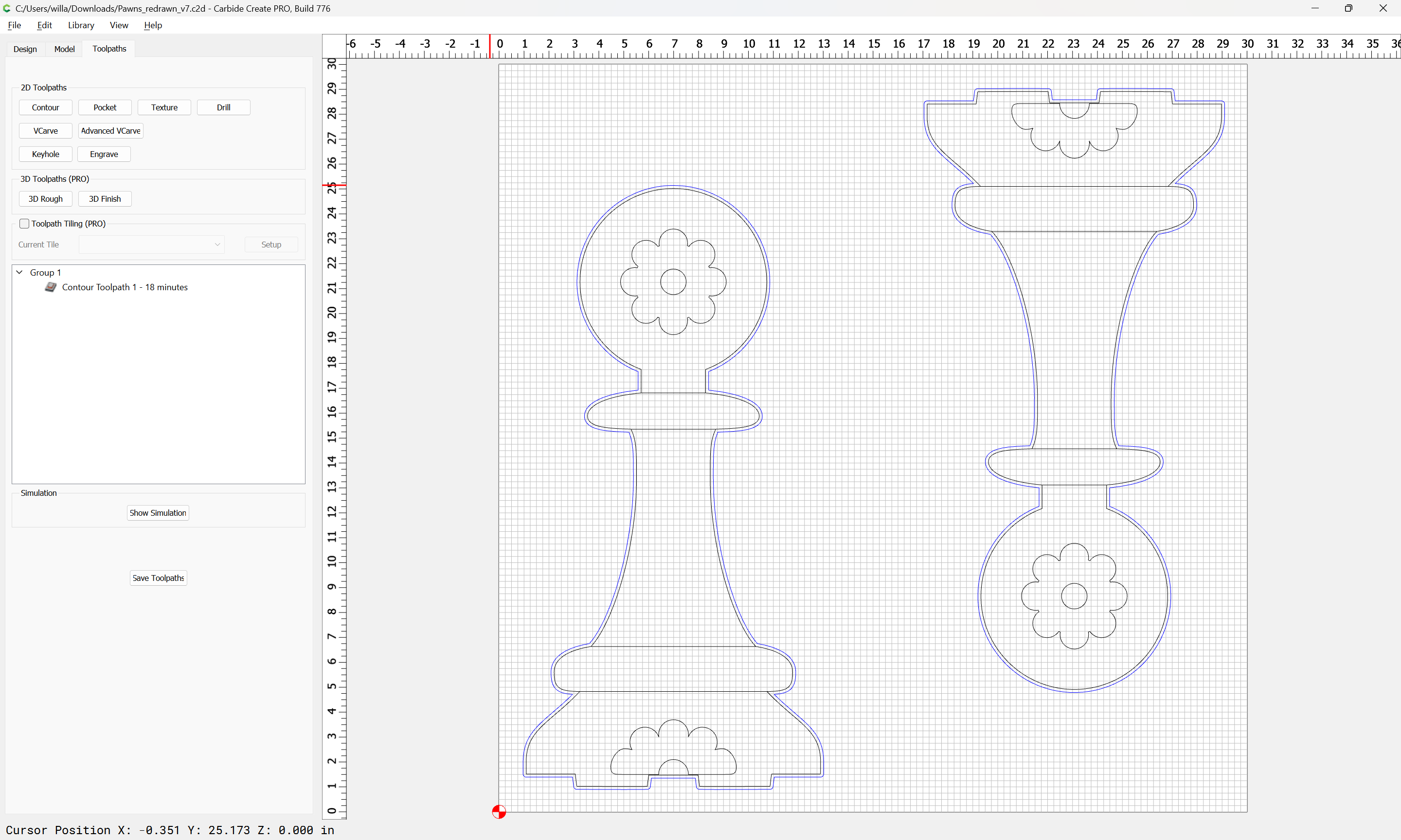
Uploaded as a v7 file:
Pawns_redrawn_v7.c2d (100 KB)
What does that geometry look like in Krita?
Are there any options in it for exporting SVGs to simplify or force curves?
Sorry for a slow response - yesterday got busier than planned.
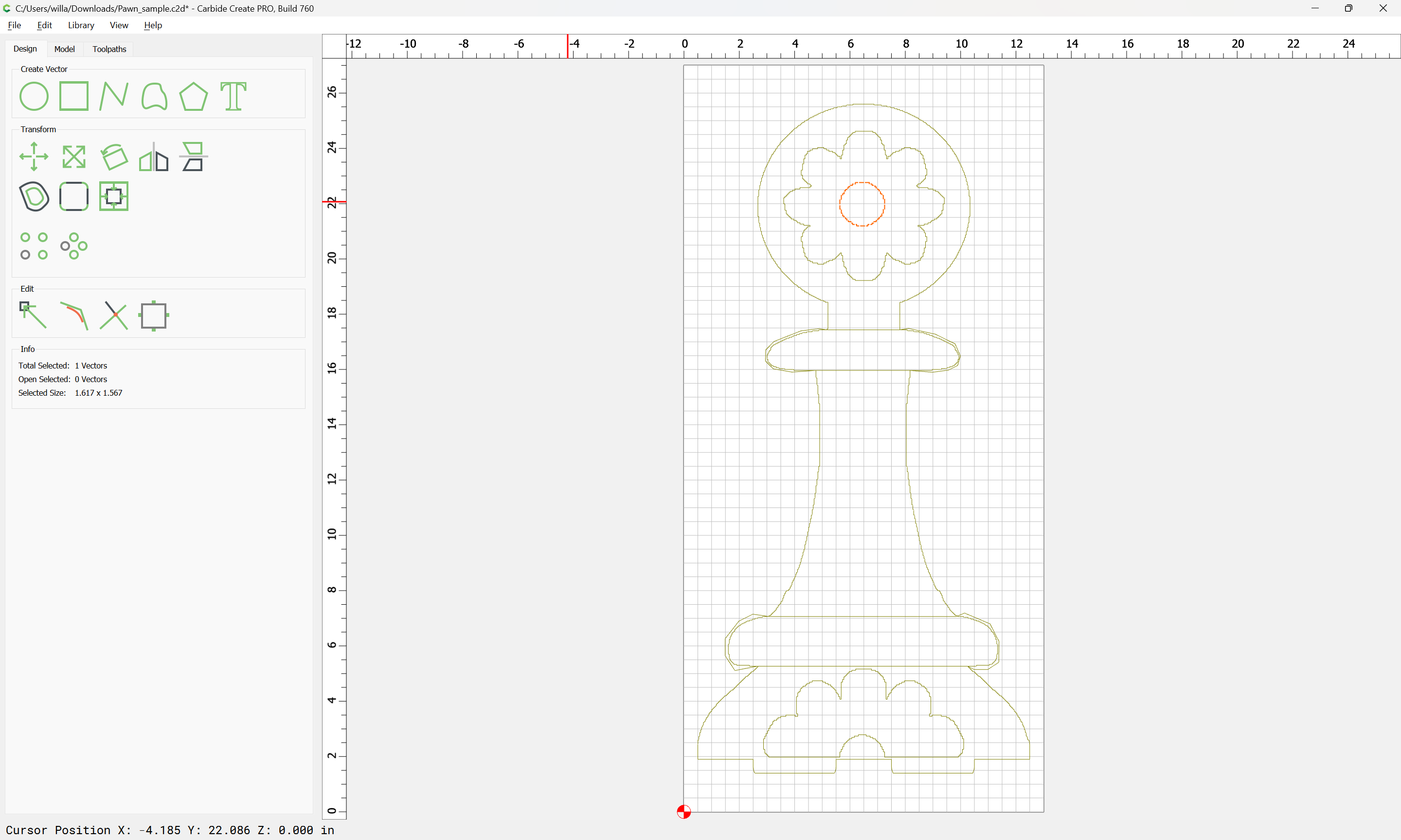
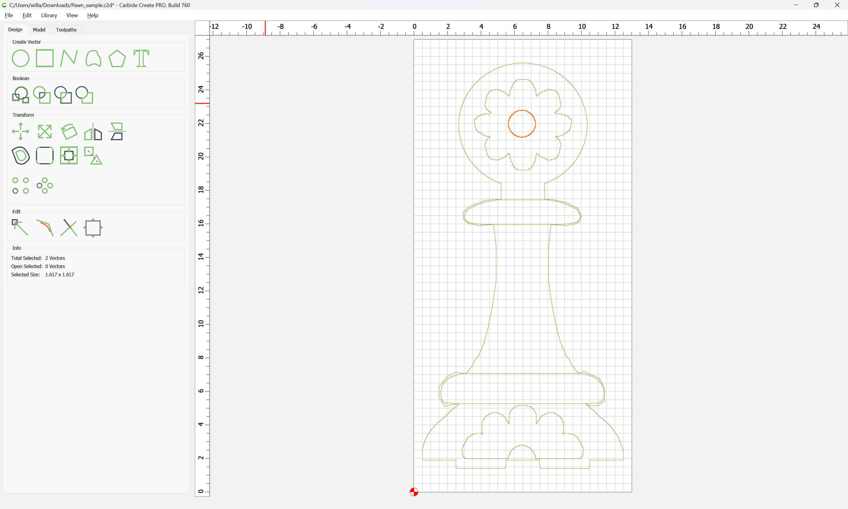
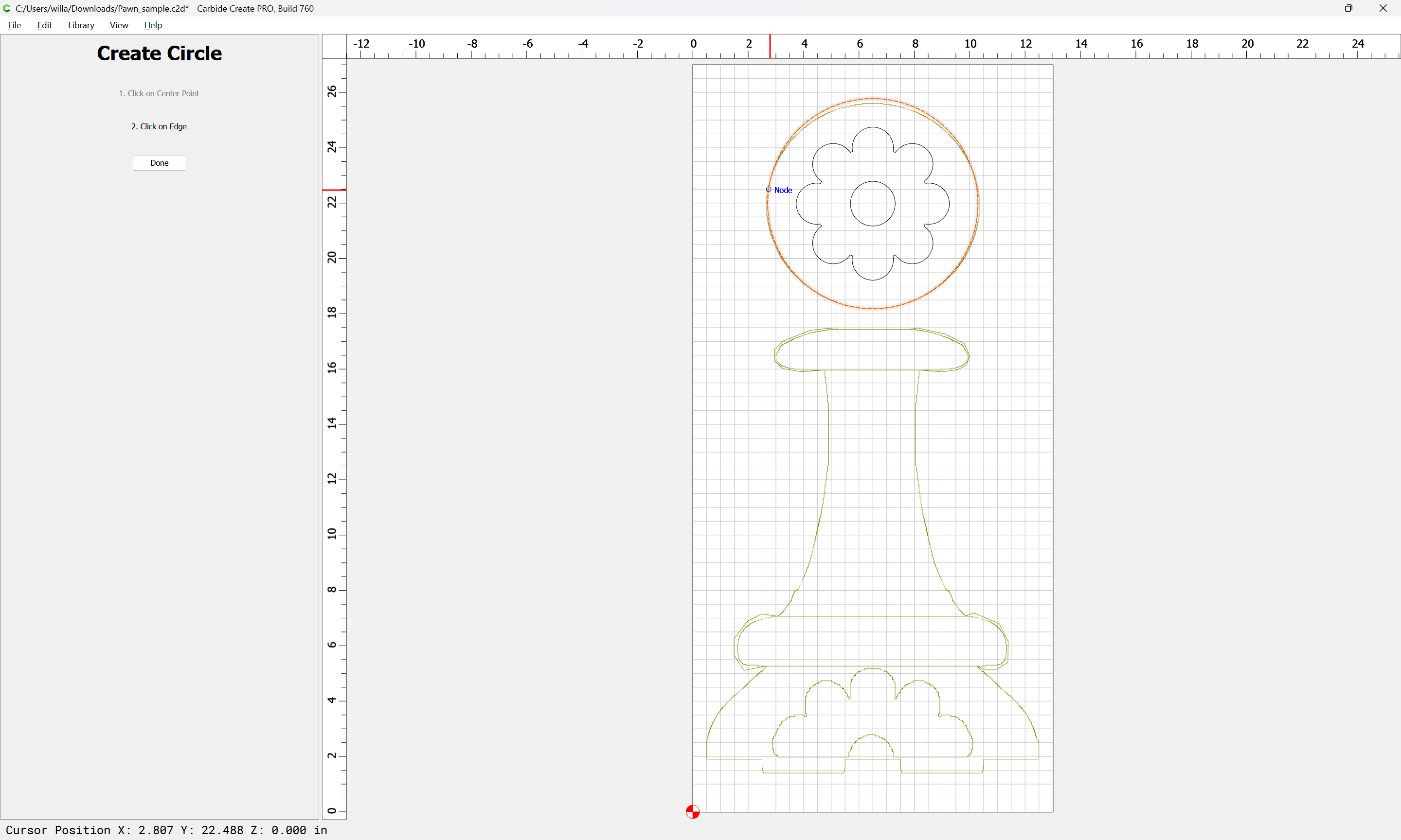
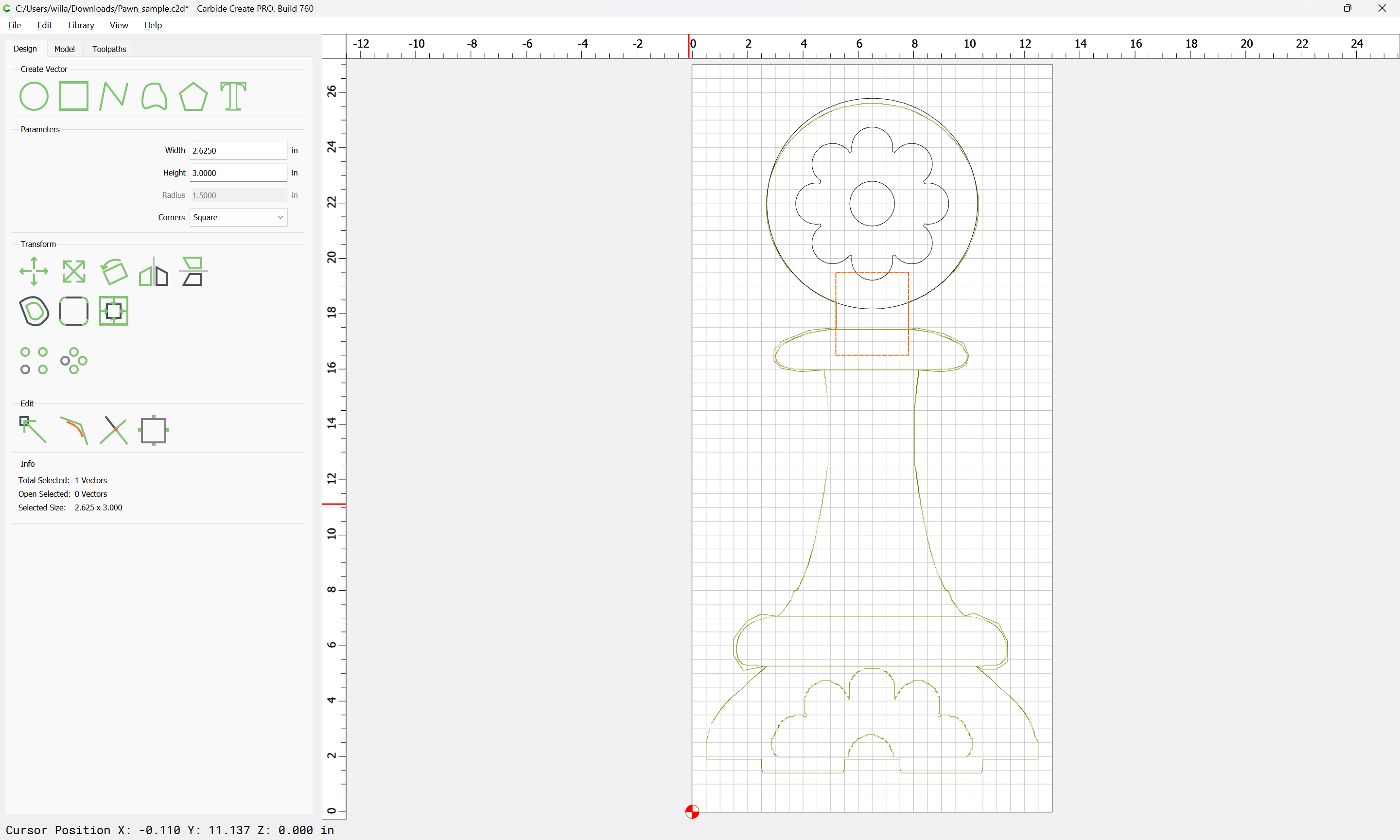
It occurred to me that the simplest way of reducing number of nodes would be to remove the circle. So I did that and it fixed the toolpath. Then I drew a new circle and used a boolean operation to attach (yeah, I know -not the best/most efficient) and that also generates a good toolpath:
PawnFromScratchReplaceCircle_774.c2d (632 KB)
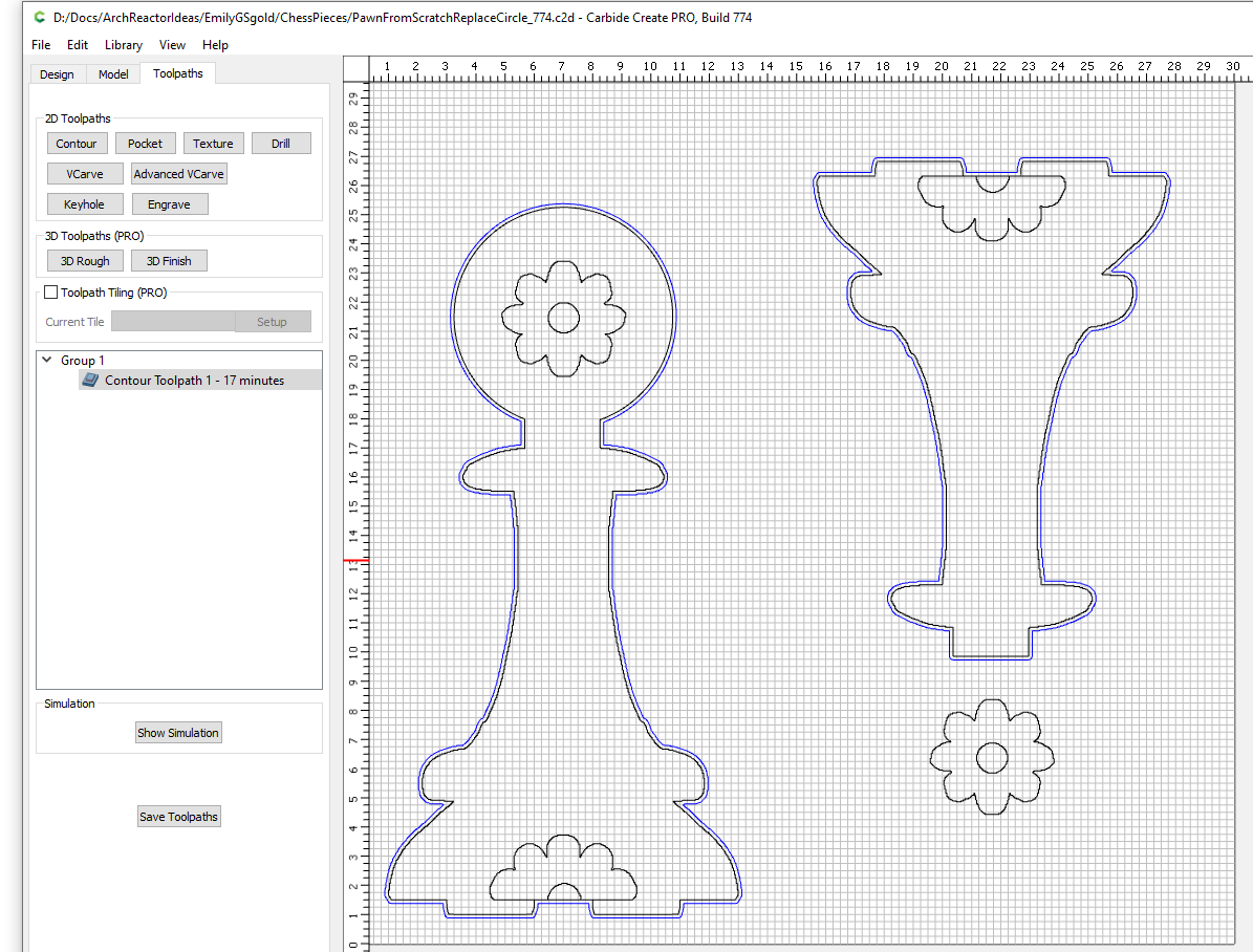
I’m going to count that as a “good enough” solve. To my untrained eye, it looks like the pawn with the circle still has an egregious number of nodes… but it works. I’m not looking for perfection as I’m just supposed to be a helper on this project… The Krita files are created by my daughter and I’m supposed to just helping her get them cut out in plywood… Too much “help” and it becomes my project and she runs out of motivation.
In answer your question about Krita, it looks like she could have chosen better vector drawing tools in Krita:
But I think the raster tools in Krita are what she normally uses. So since it’s the drawing tool she was familiar with… anything more “CAD-like” was too overwhelmingly different.
Last but not least - THANK YOU. I’ve learned a lot from your examples above and I’ll definitely be doing it differently next time.