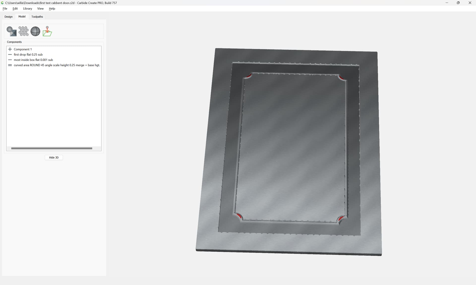
Been trying to layout a potential cabinet door all morning.
While the MODEL layout shows a simulation that is about what I’m looking for, the Toolpath doesn’t show up correctly when simulated.
Hoping someone can look at the file and tell me why the Toolpath doesn’t show correctly? first test cabbent door.c2d (516 KB)
That doesn’t do it.
I’m trying to get the door to be a raised door with the center at the same height as the outside edge (rails and stiles).
There is a depression of 1/4" before the “rounded” lift up to the middle section.
If you look at the “Model” simulation, it shows correctly. However, when I do the Rough/Final cuts, the Toolpath doesn’t show up the drop around the middle section???
A further consideration is that you are using a tiny tool — I’d suggest a #102 at the smallest for roughing, and note that if you go down to the tools which have short cutting flutes and shanks wider than the cutting diameter it is on you to make certain that you aren’t cutting up against vertical (or nearly so) features which are taller than the cutting flutes.
Cut the 1/4" recess with a 1/4" pocket (DOC 0.125, feed 90),
then an 1/8" Rest mill (default values for hardwood).
Then just finish 3D cut the bead with a 1/16" tool (0.015 stepover, 90 IPM).
Sorry for the delay. Just got back home.
Tod1d: Used your suggestions and looks like that will be the solution.
I will cut a sample tomorrow and see how it goes.
Thanks to all. Appreciate the help and will try the model method Will suggested after I get a sample done.