Some days I think I’m taking two steps forward and three backward.
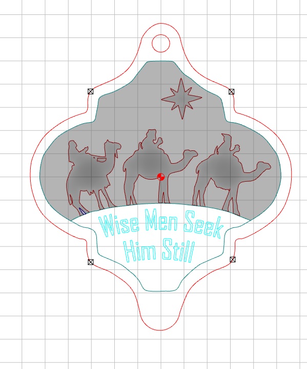
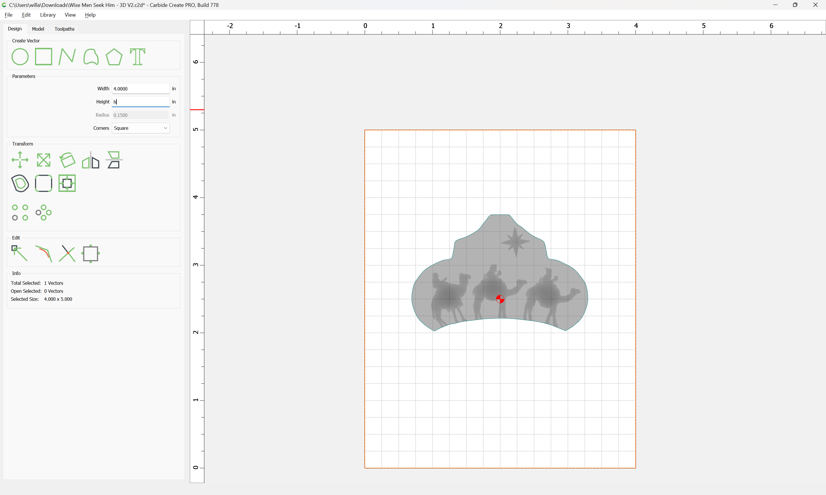
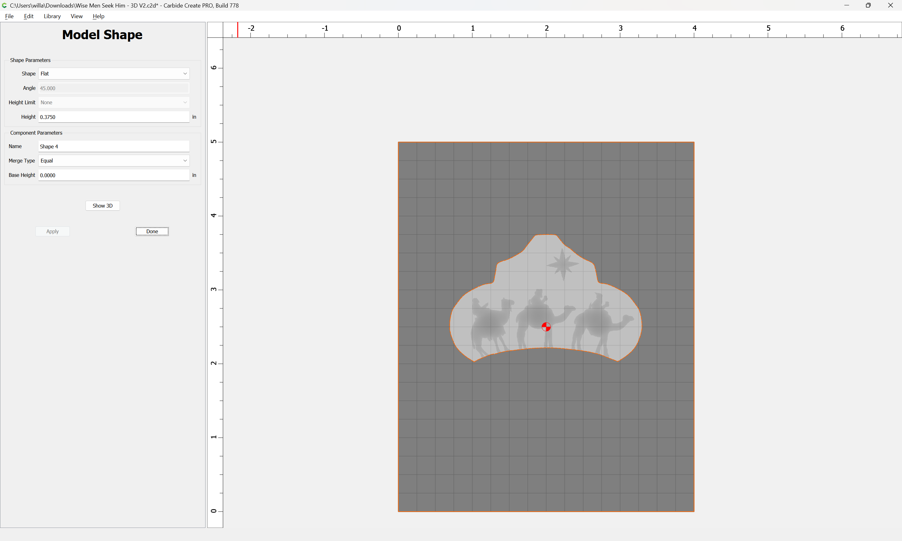
Tonight’s Bedtime Question: when selecting a vector to be modelled, why does the Toolpath simulation show it cutting beyond the bounds of the vector? On a Christmas ornament design, I’ve established the basic design in a relatively few vectors. One is the outline for one portion of the ornament, which serve as the background for characters. Immediately below that section is a “Stage” for text.
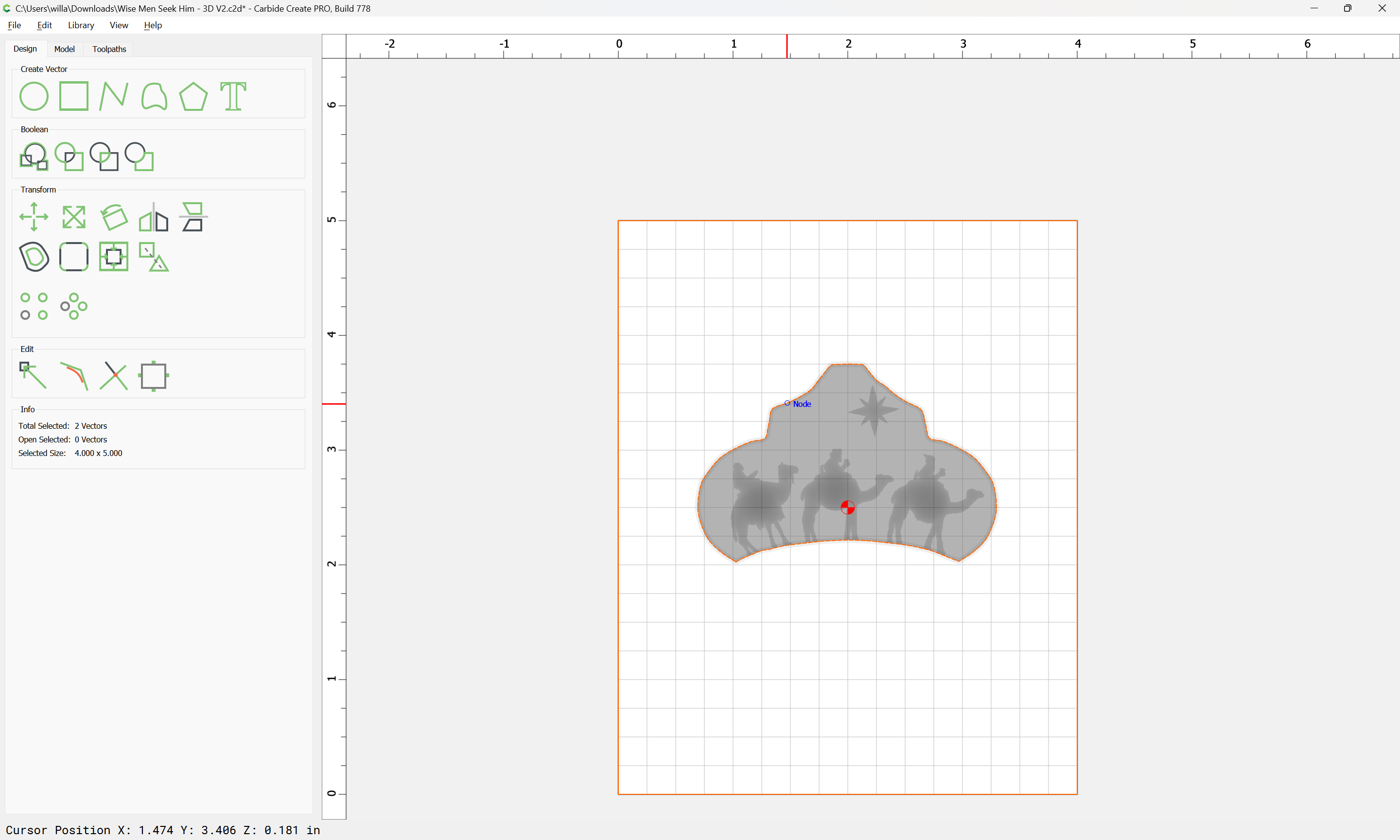
The red outer line serves as the overall boundary for the ornament. Within that are two close vectors which define the “Character area” and the “Stage” where text appears.
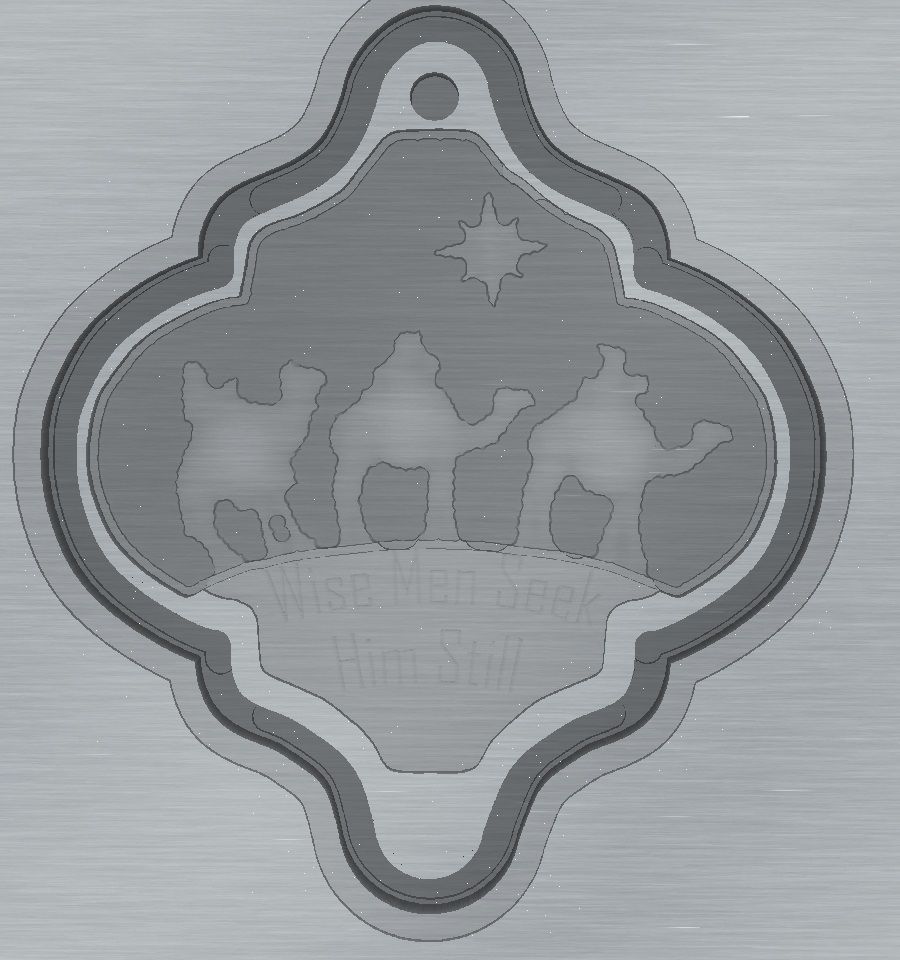
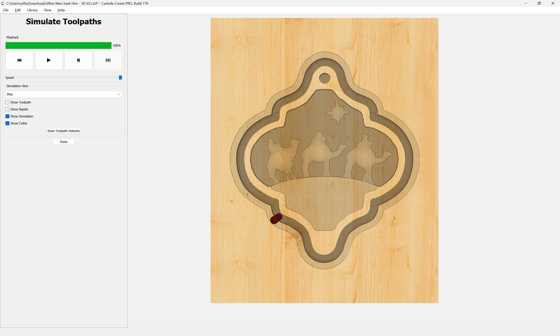
Below is a screenshot from the Toolpath Simulation.
The black indicates the cut which separates the ornament from the board. The lighter area inside of that is the raised frame of the ornament, the sides of which are supposed to be about 1/10" wide.But notice that the stage, which is cut using 2D pocketing is invaded by the characters and their background above it. And, the outer rim or frame of the ornament is also invaded by the 3D cutting, First and worst, by the Rough Pass and a bit less by the Finish Pass.
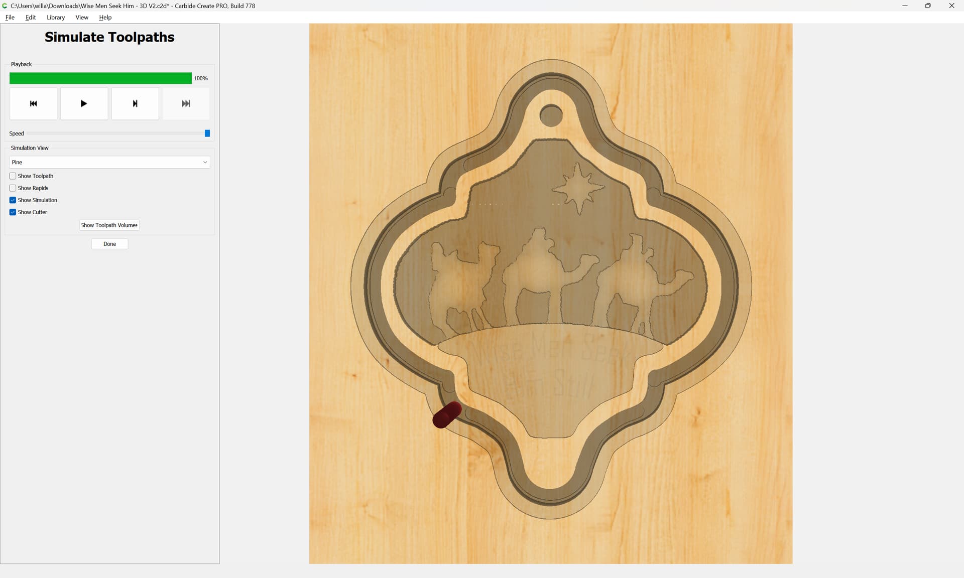
I think what you are seeing is how the ‘edge’ of a region is treated, and how it’s treated for 2D pockets/contours and 3D toolpaths.
For 2D pocket toolpaths, the tool comes up to, but does not cross the edge. For 3D toolpaths, the tool center comes up to, but does not cross the edge.
So, the ‘invasion’ you are seeing is half the width of the tool, and thus is worse for the rough (larger tool) toolpath.
Now I’m remembering the how and why of what Will demonstrated for me some days ago. But for whatever reason, I really want the final cutout to be done with the contour function.
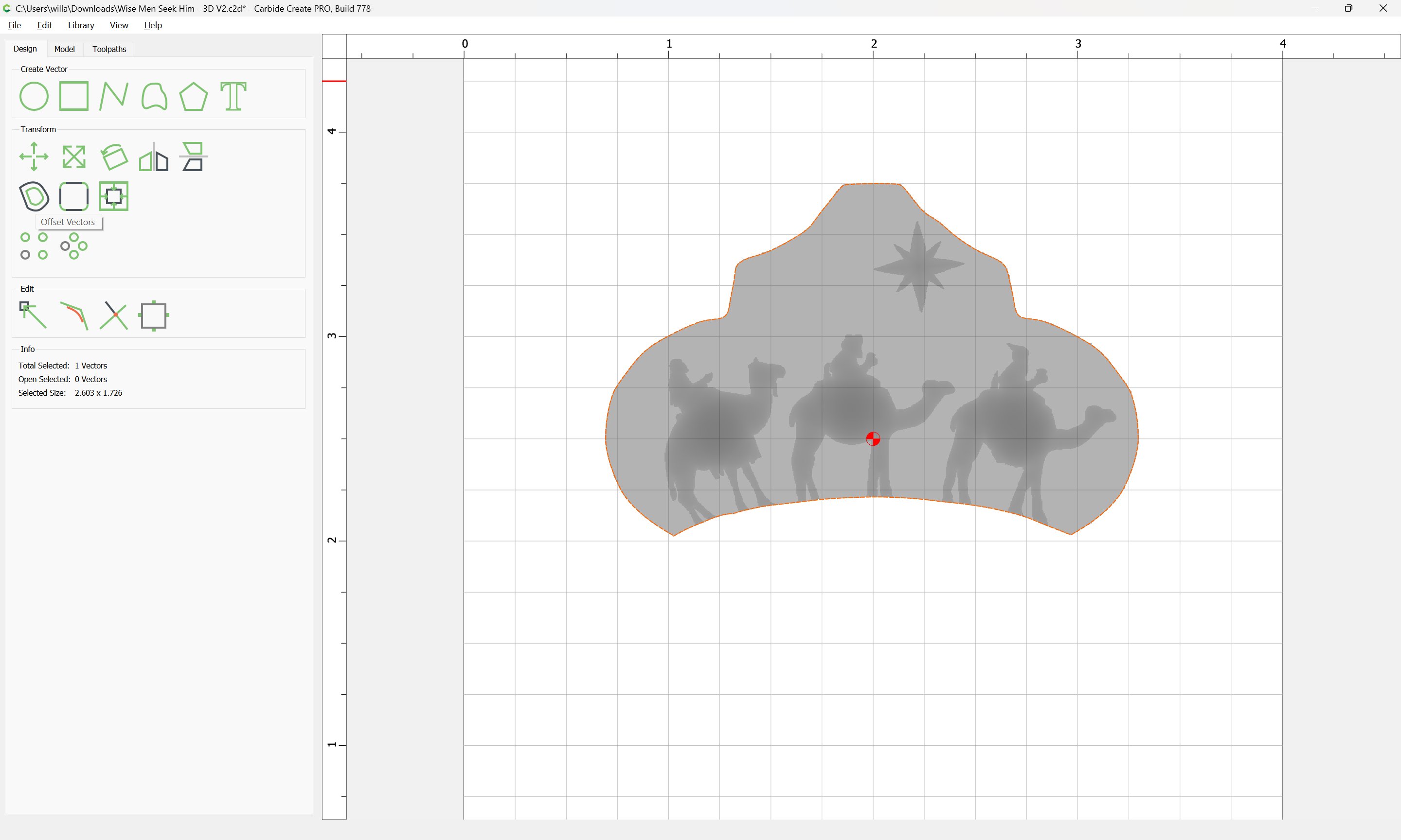
The issue is that you do not have a geometric representation which will allow selecting a region for the 3D toolpaths to cut which will limit said toolpaths to the area of the 3D.
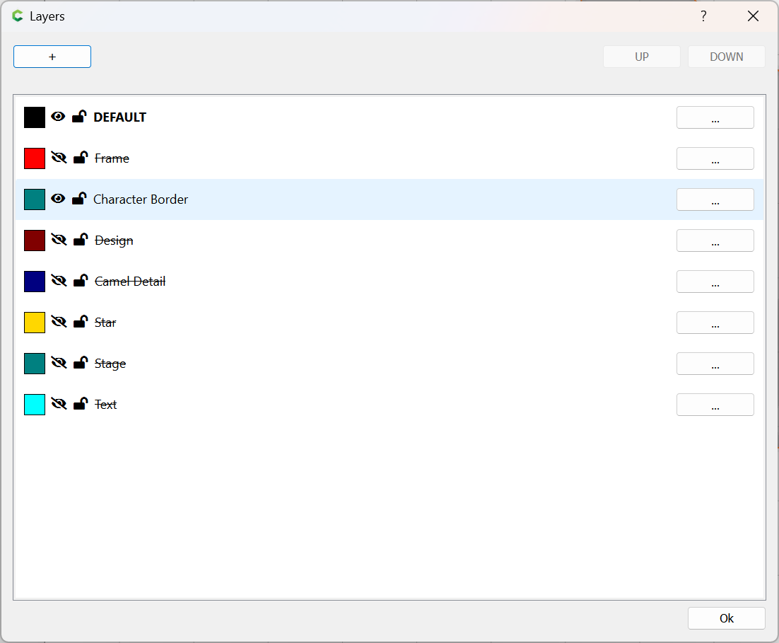
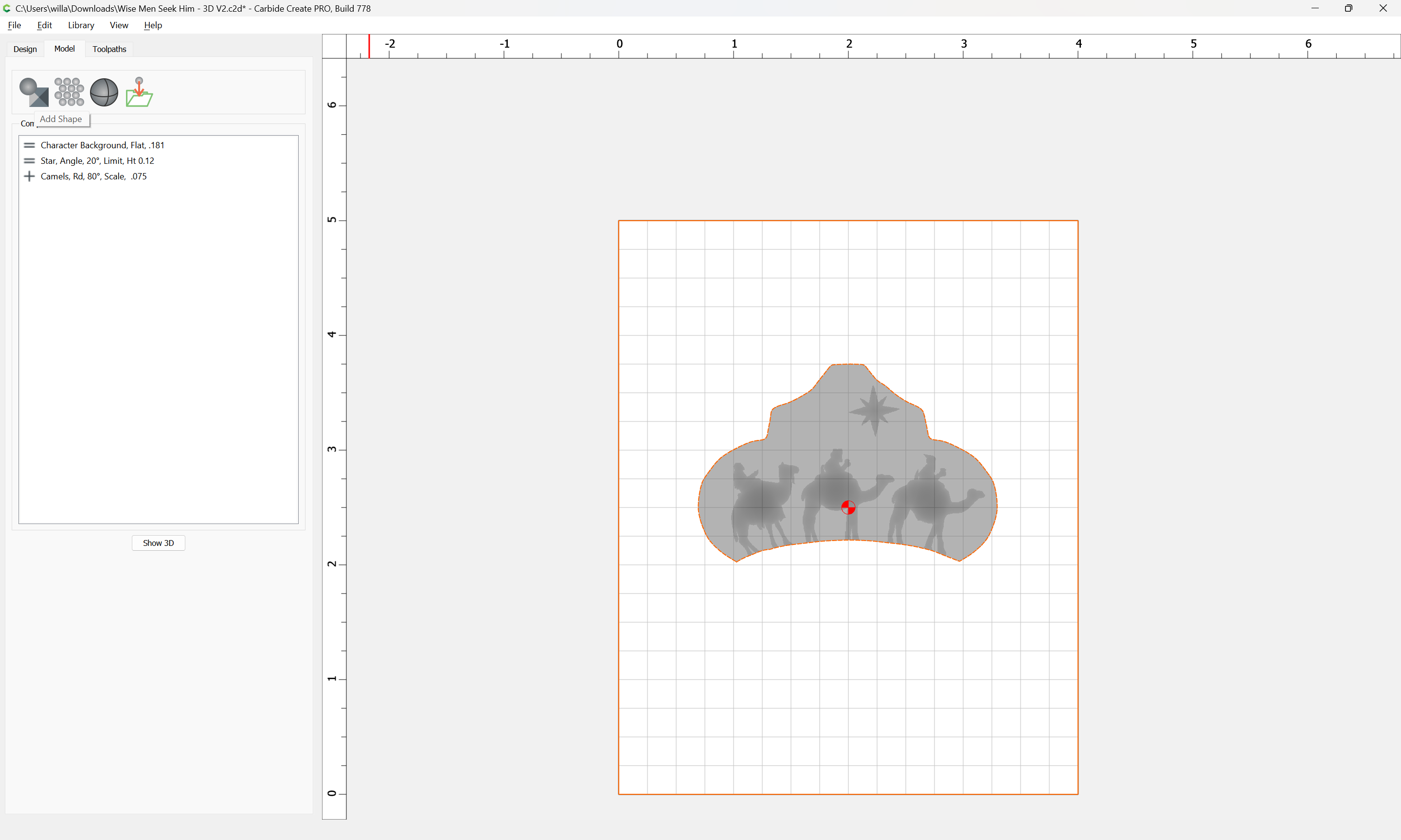
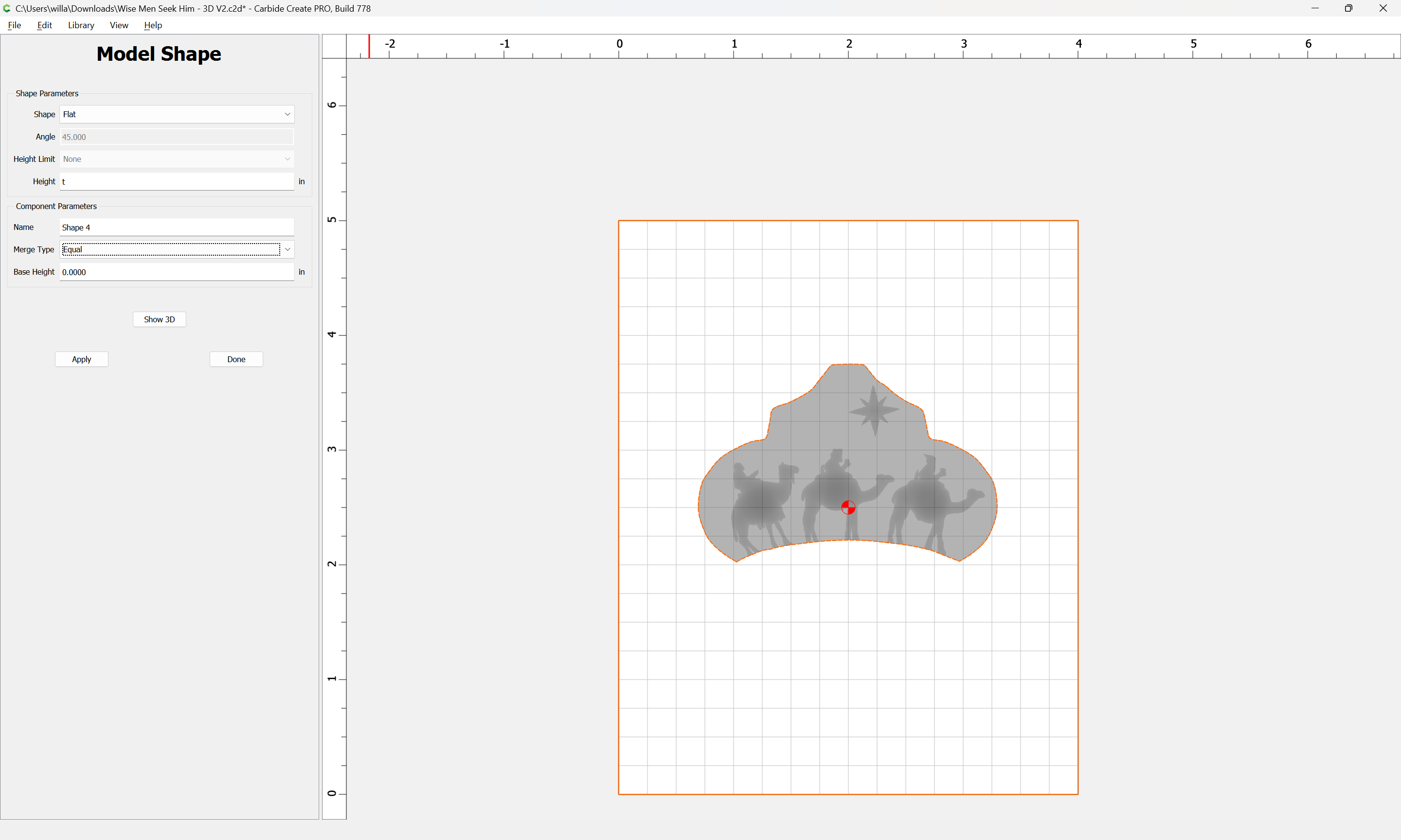
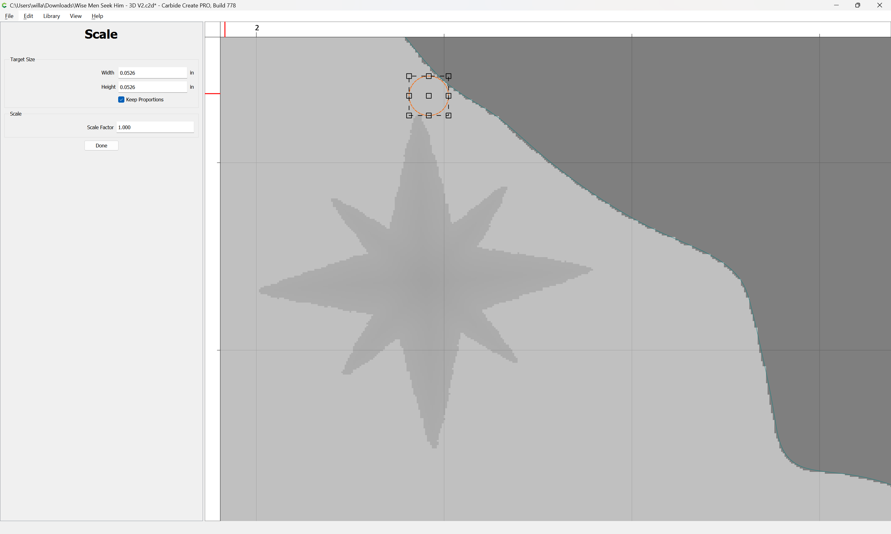
The easiest way to limit this sort of thing is to select the “Character Border”: