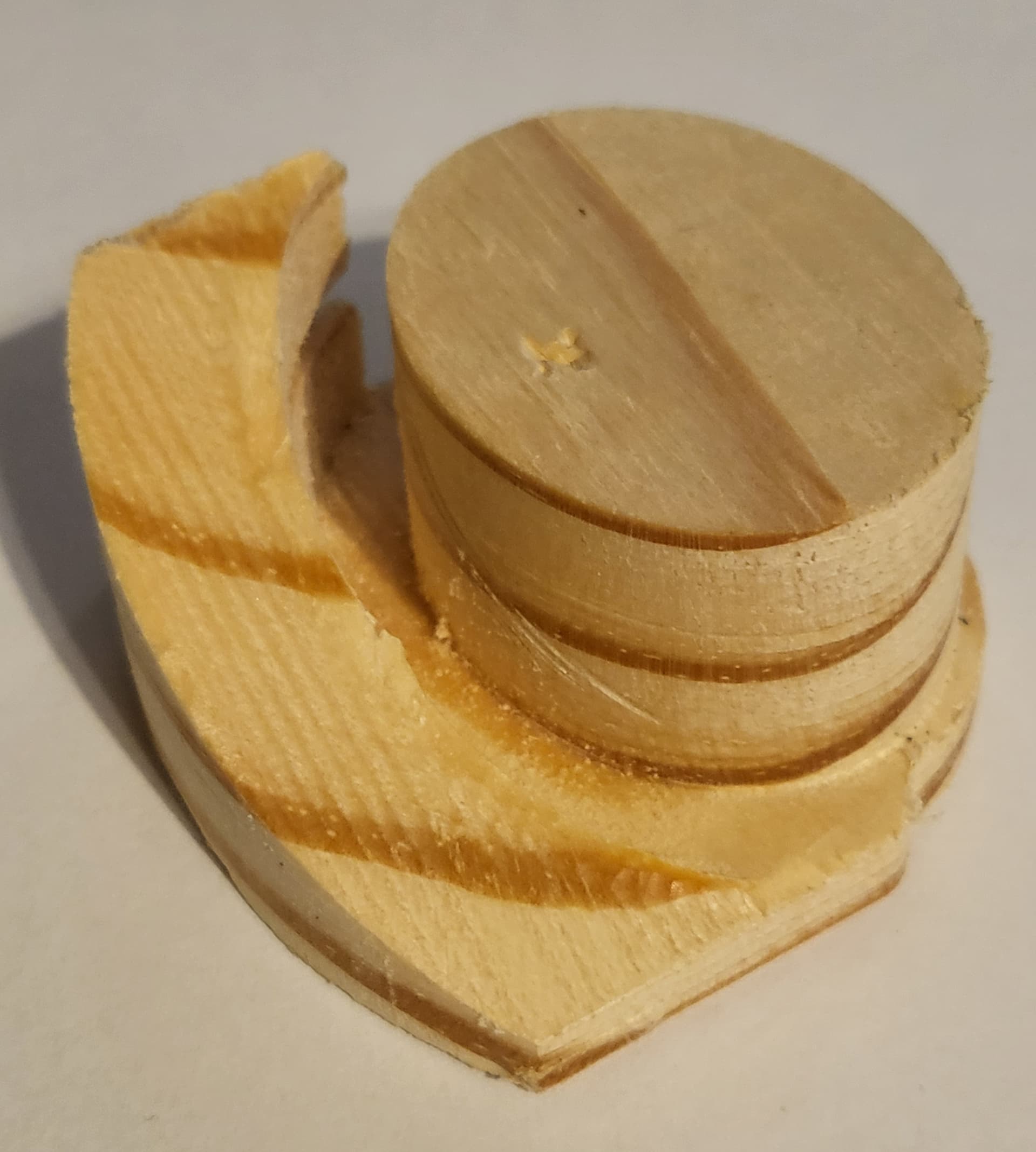
This came in as a tech support request:
I don’t see a way to create the pictured part in Carbide 3D Pro.
Is it possible?
The short answer is, “Yes.” for the long answer and how-to, see below.
This came in as a tech support request:
I don’t see a way to create the pictured part in Carbide 3D Pro.
Is it possible?
The short answer is, “Yes.” for the long answer and how-to, see below.
The part is about 2.5 " by 2" and 1" thick.
We will need a stock area comfortable larger than that:
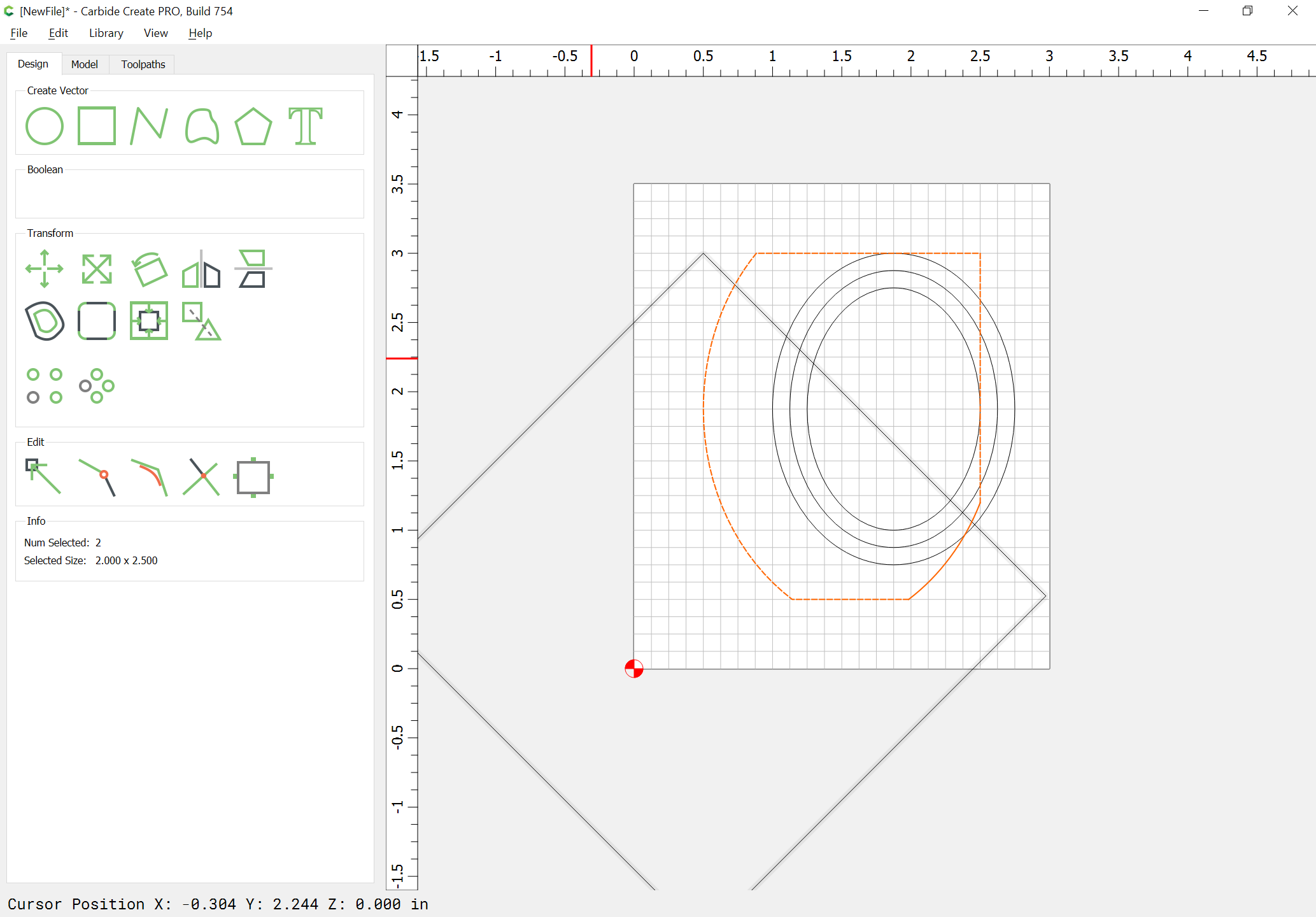
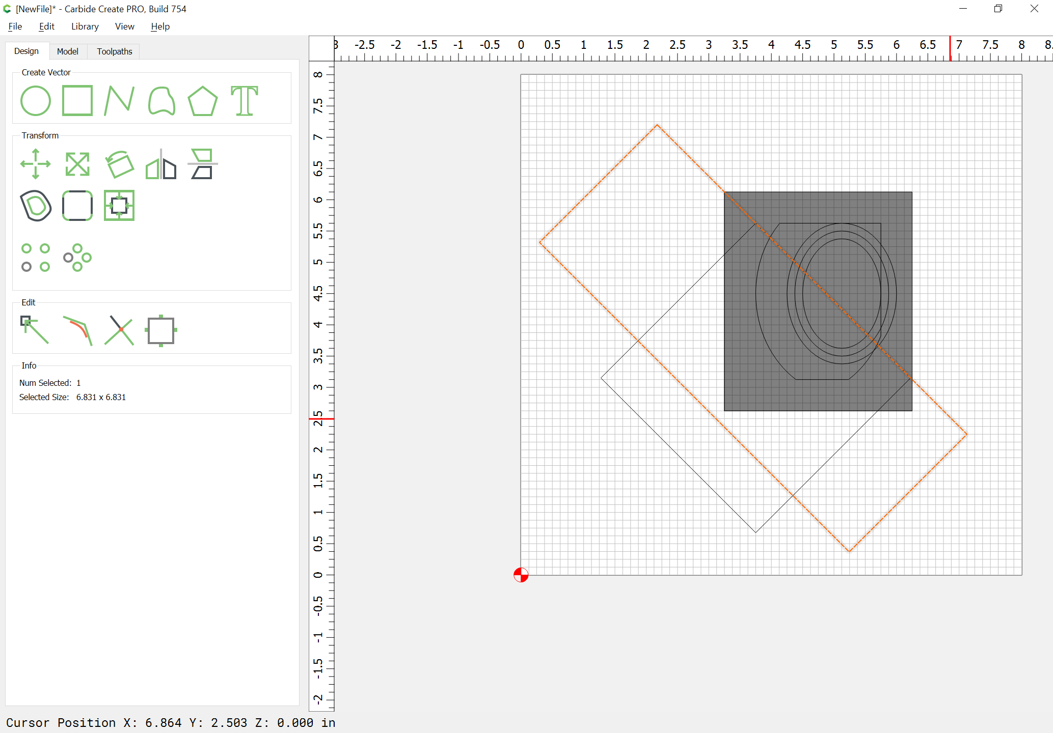
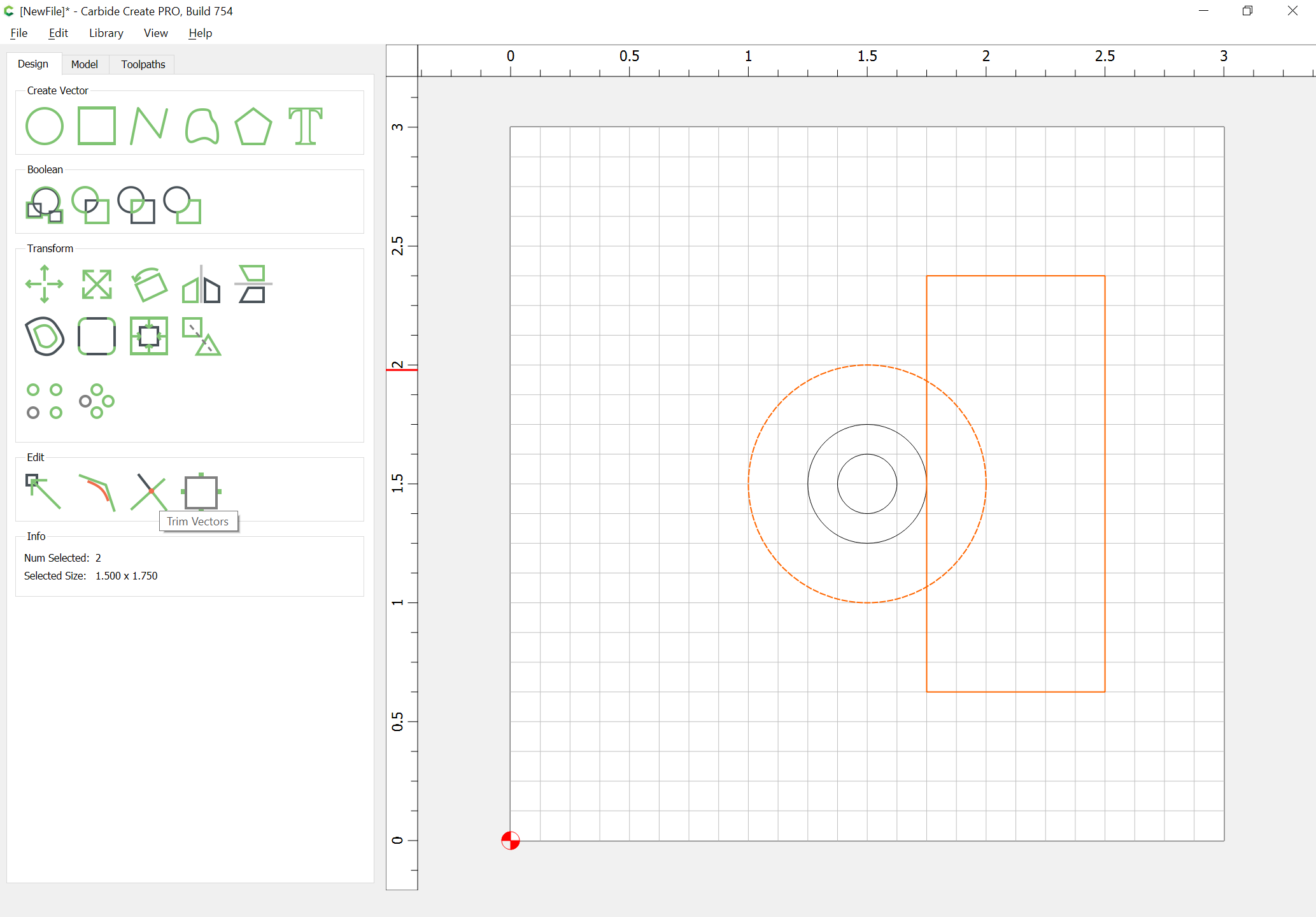
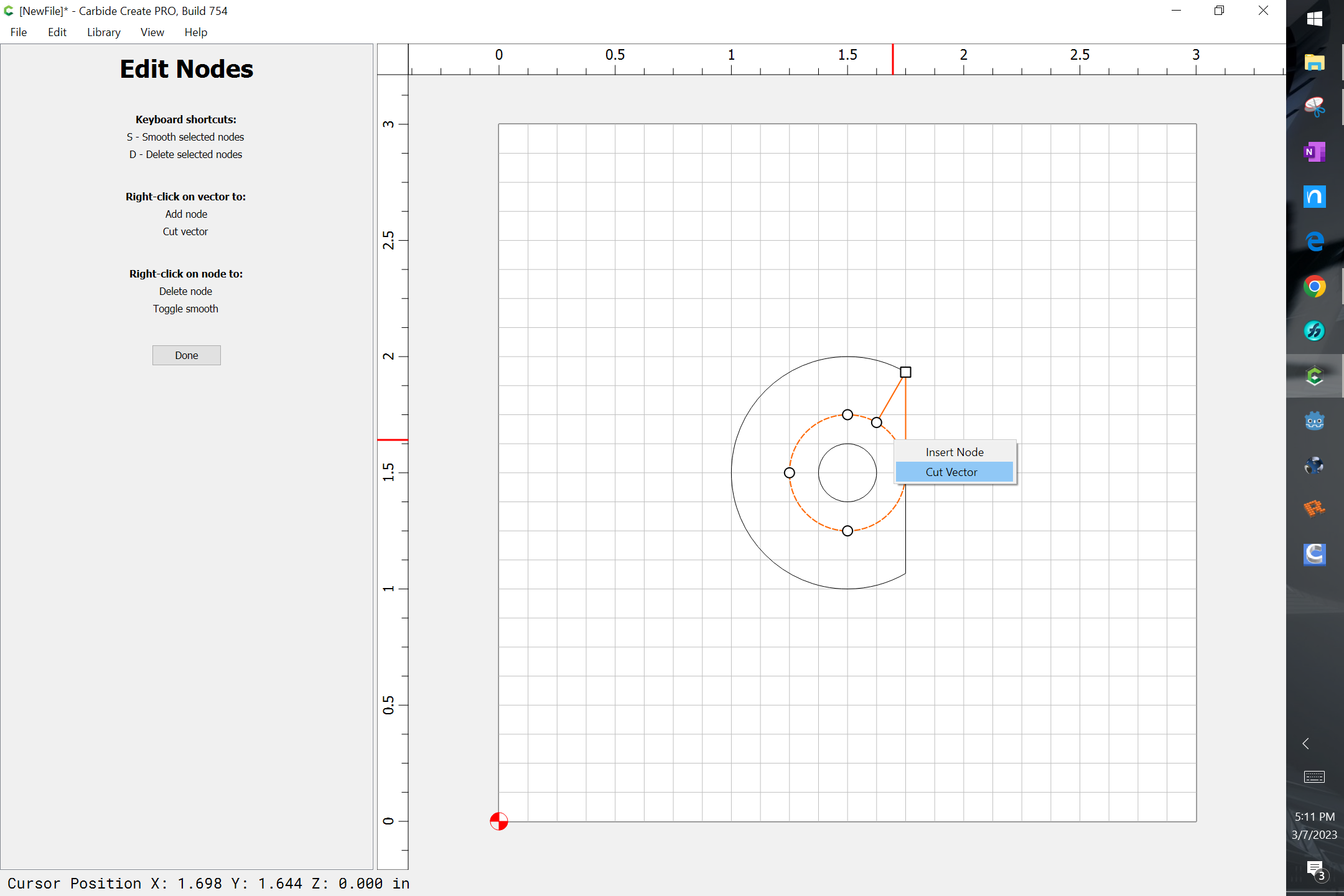
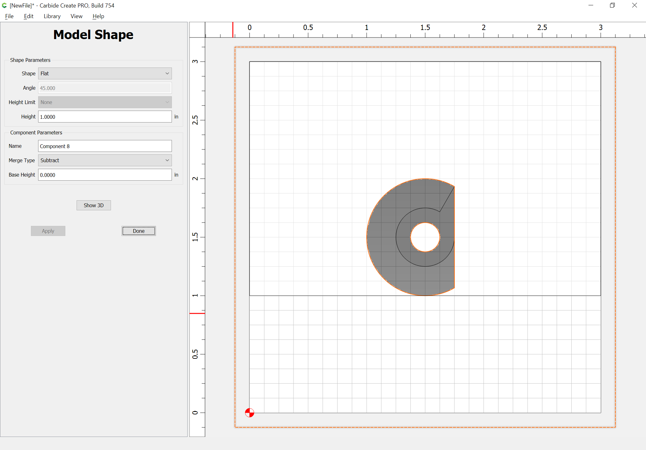
Then draw in some geometry which describes a top-down view of what we want to cut:
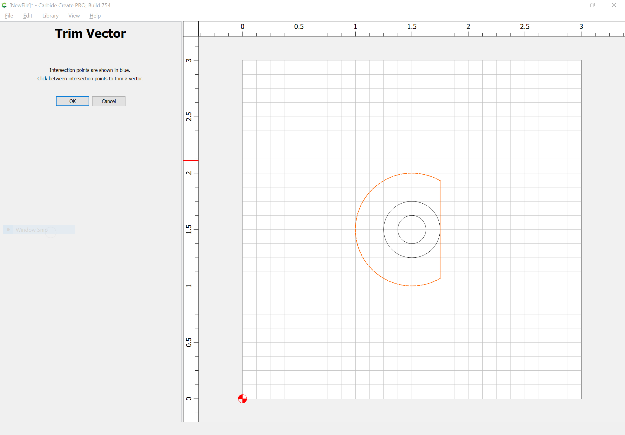
and use the Trim Vectors command and some additional geometry to arrive at outlines which are then Joined together:
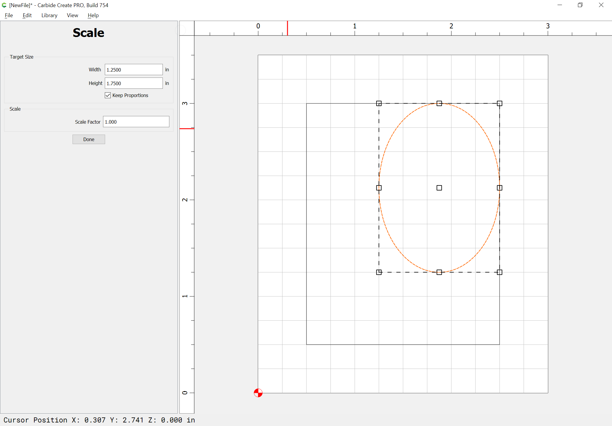
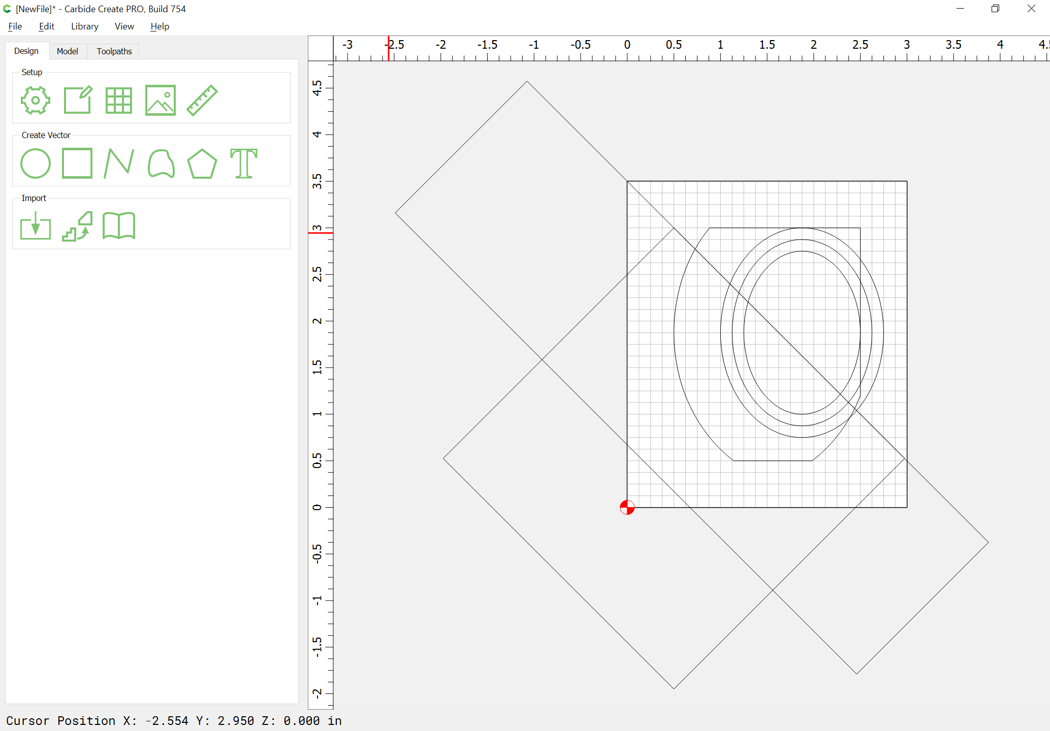
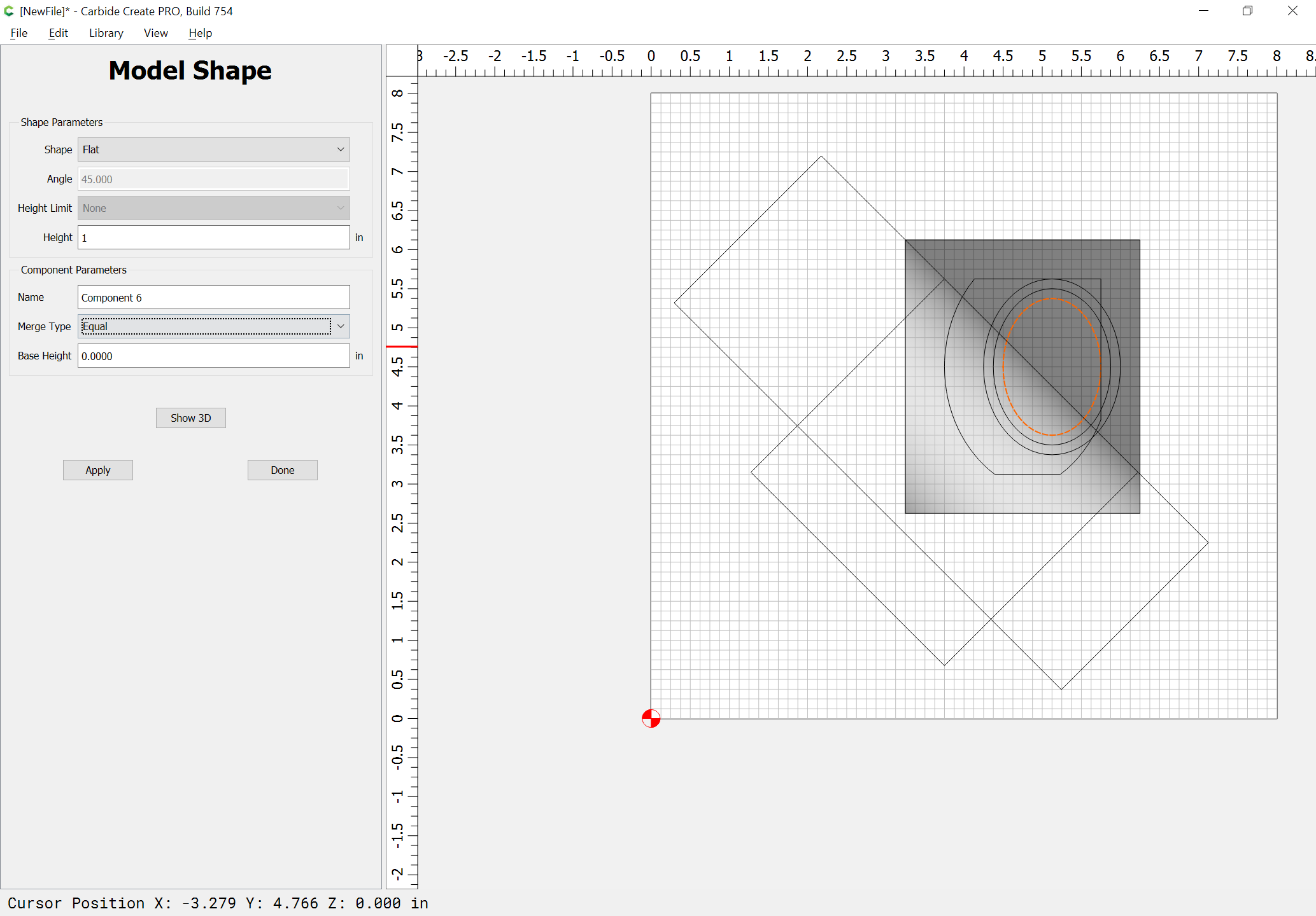
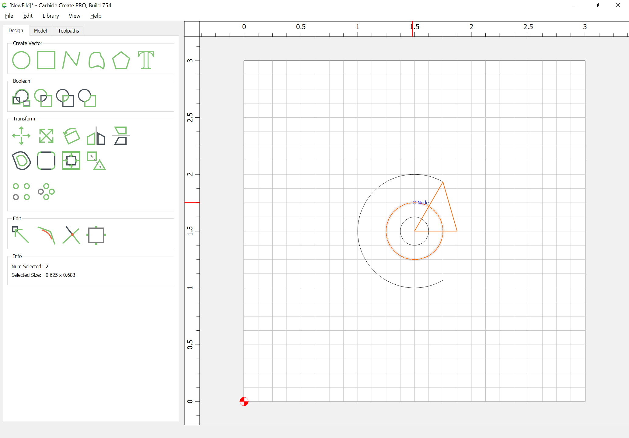
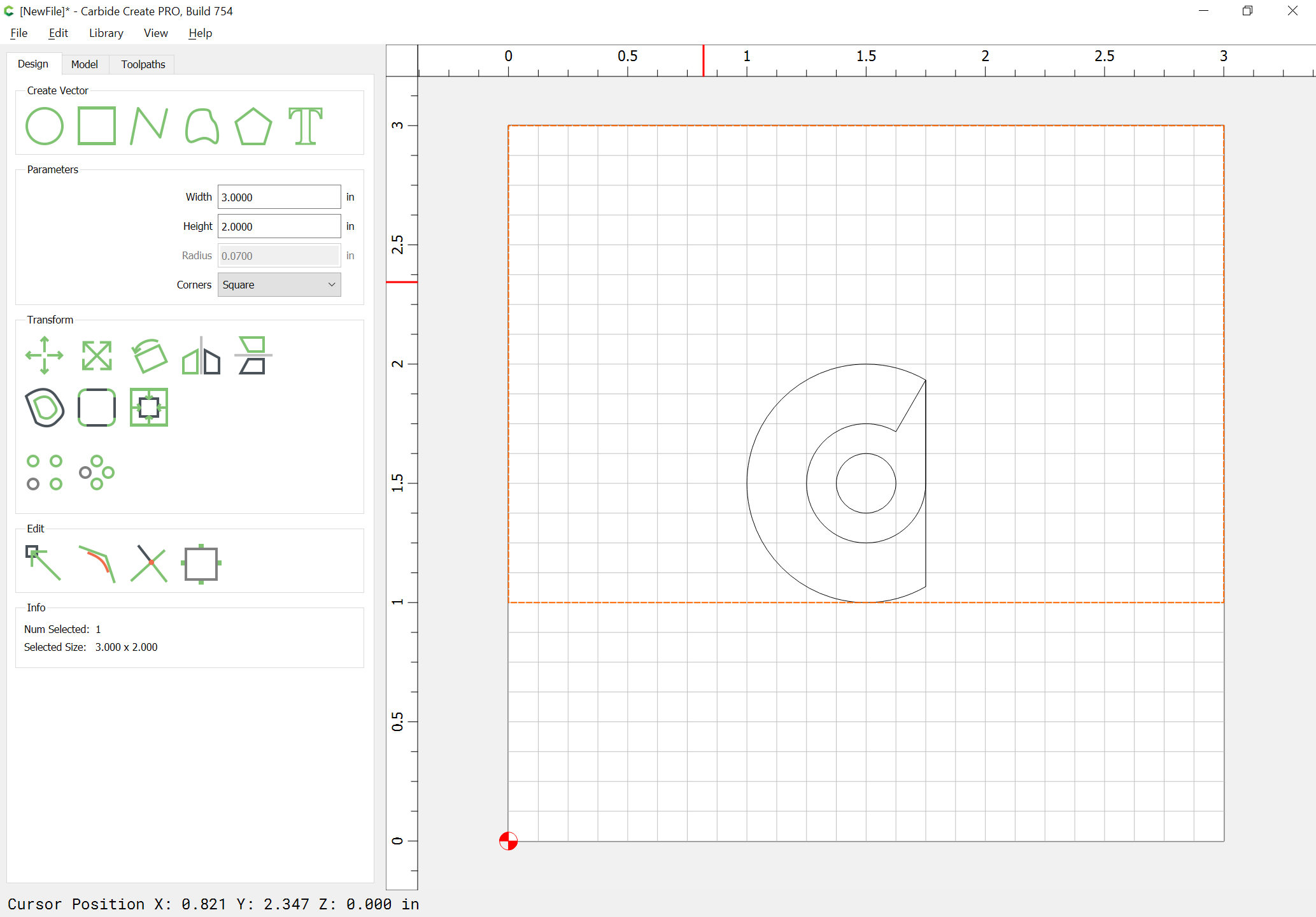
Then we draw in geometry which exceeds the bounds and which can be used to begin to model the shapes:
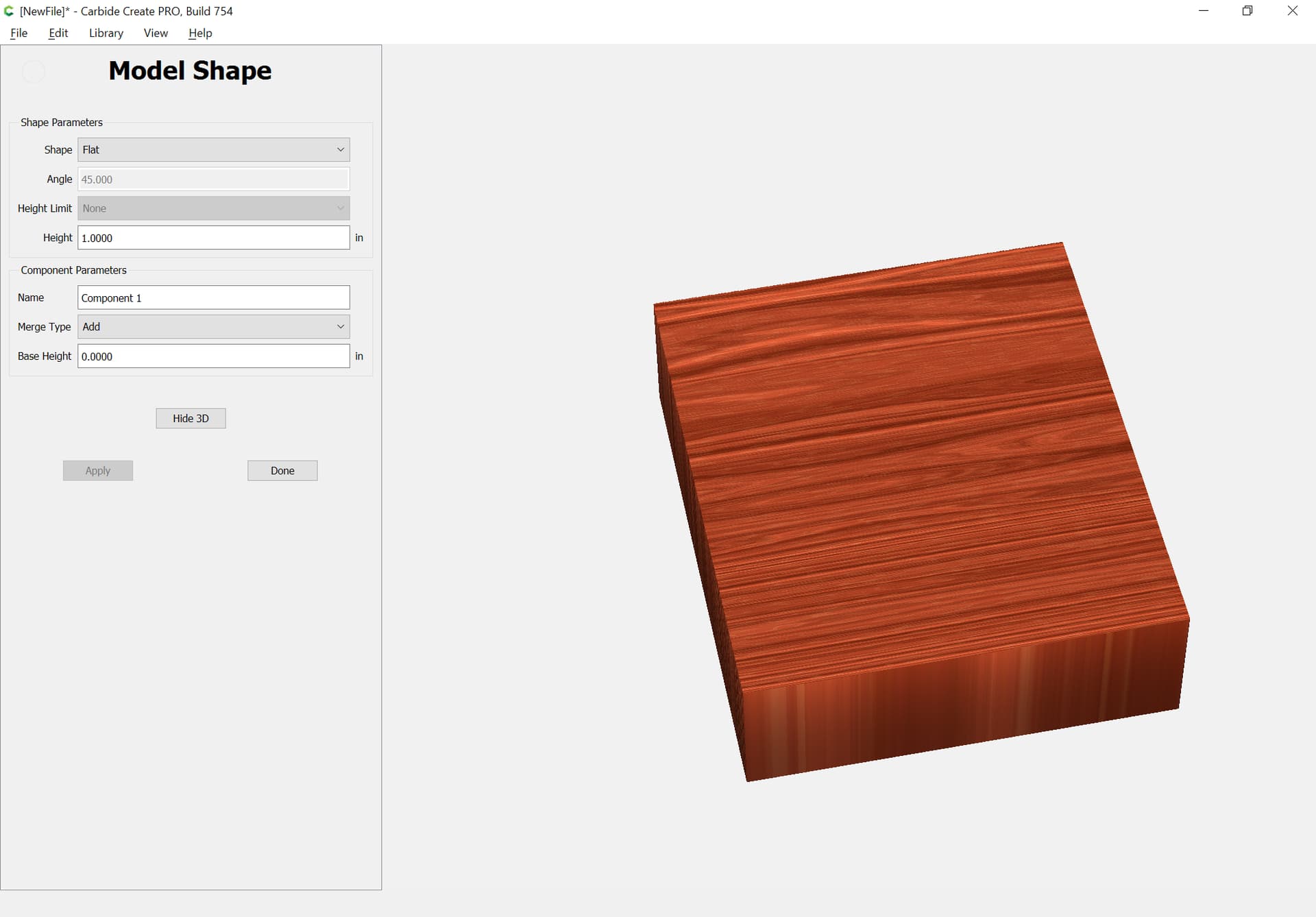
Begin by adjusting the stock size to encompass all the geometry:
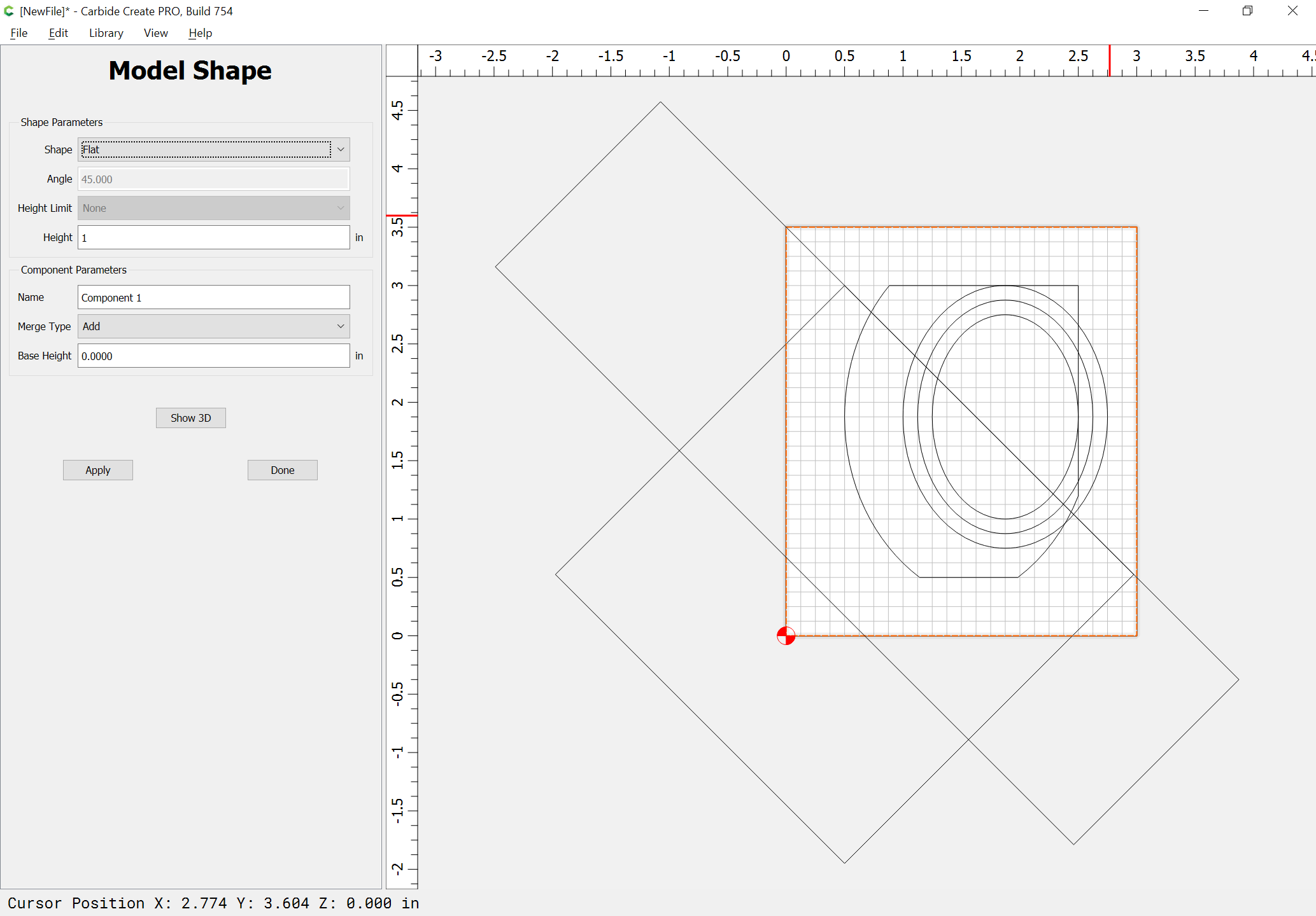
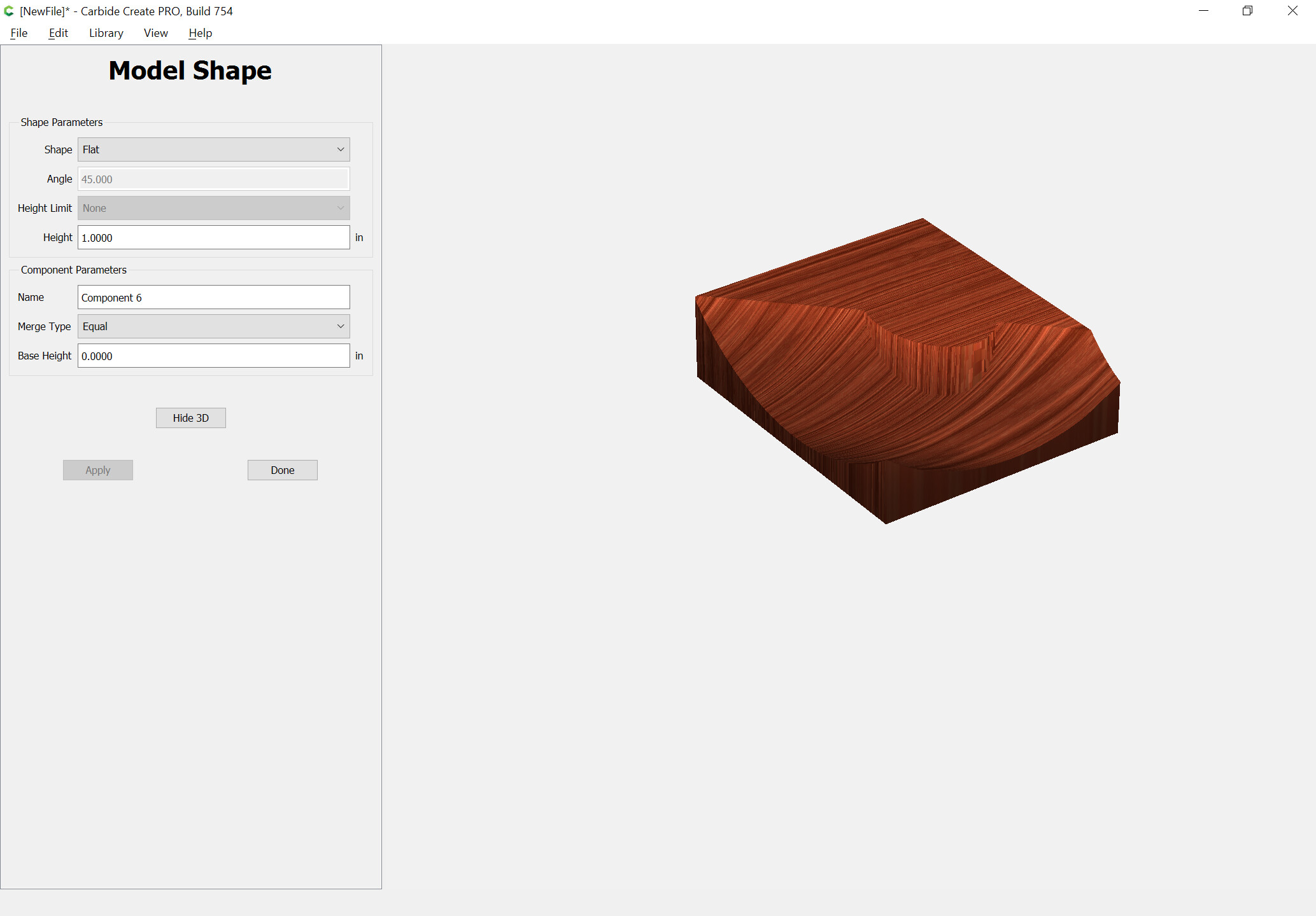
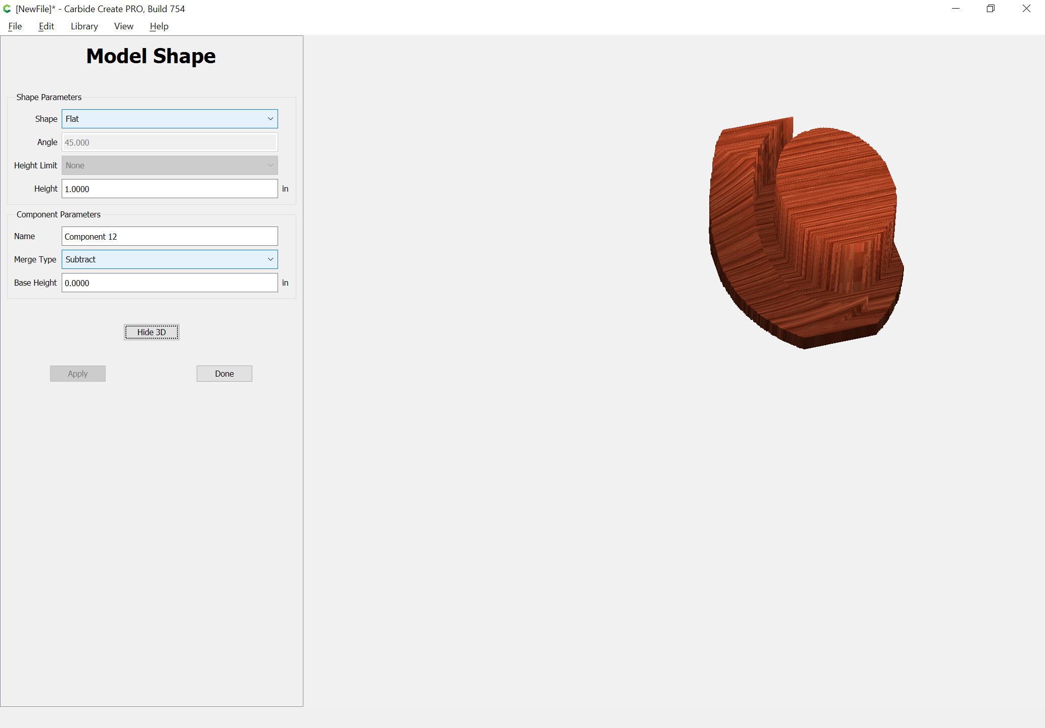
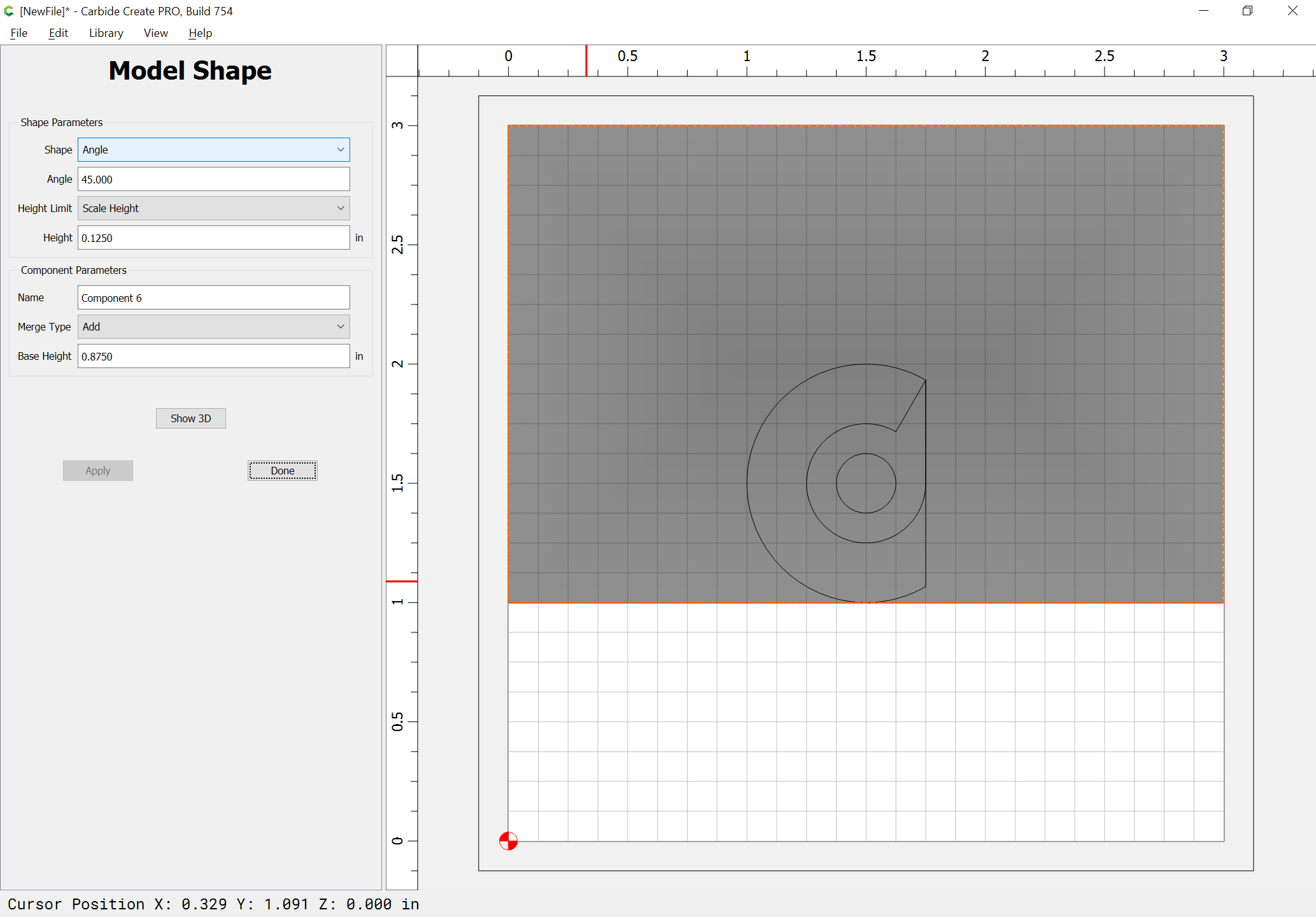
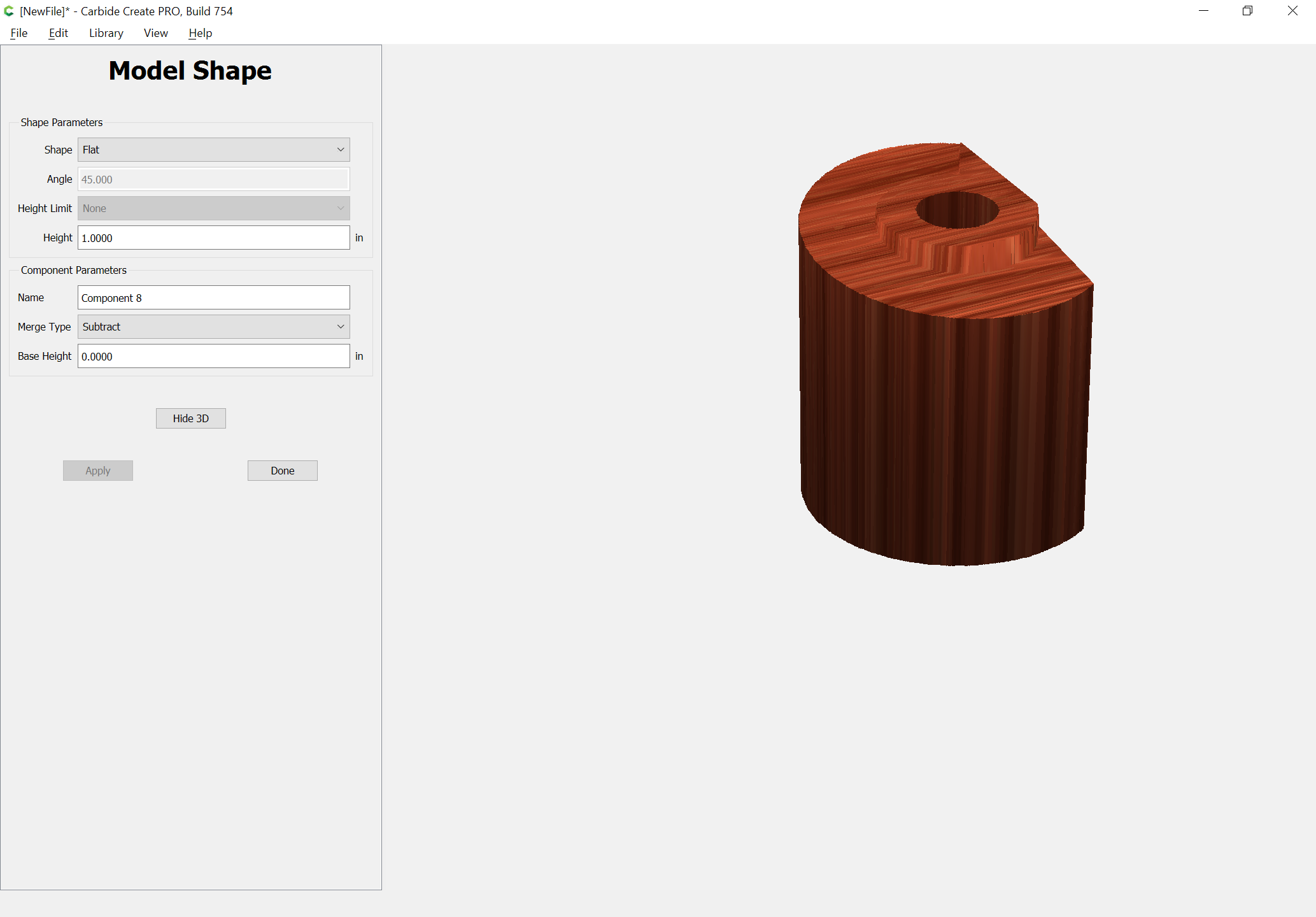
Then, model the full thickness:
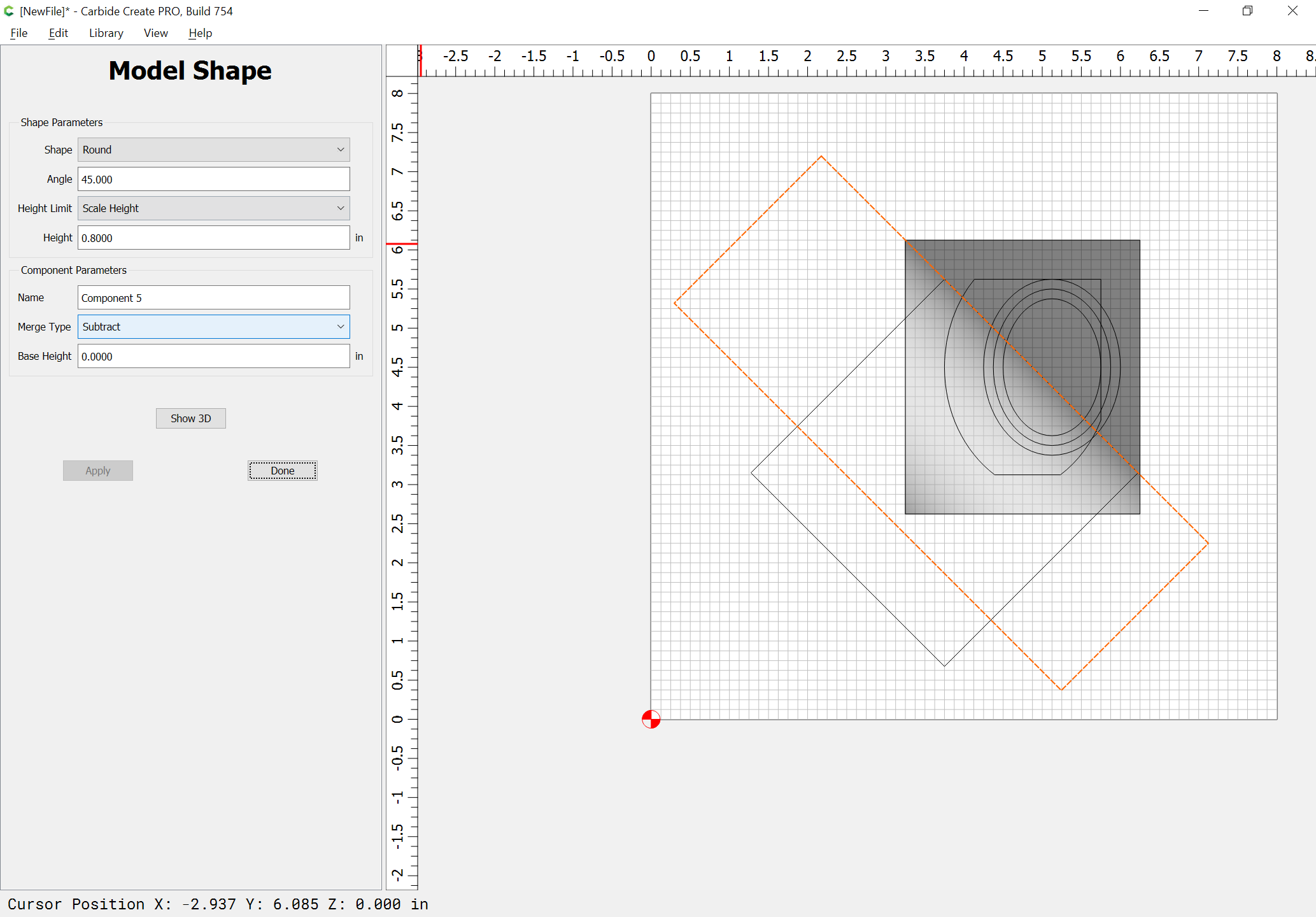
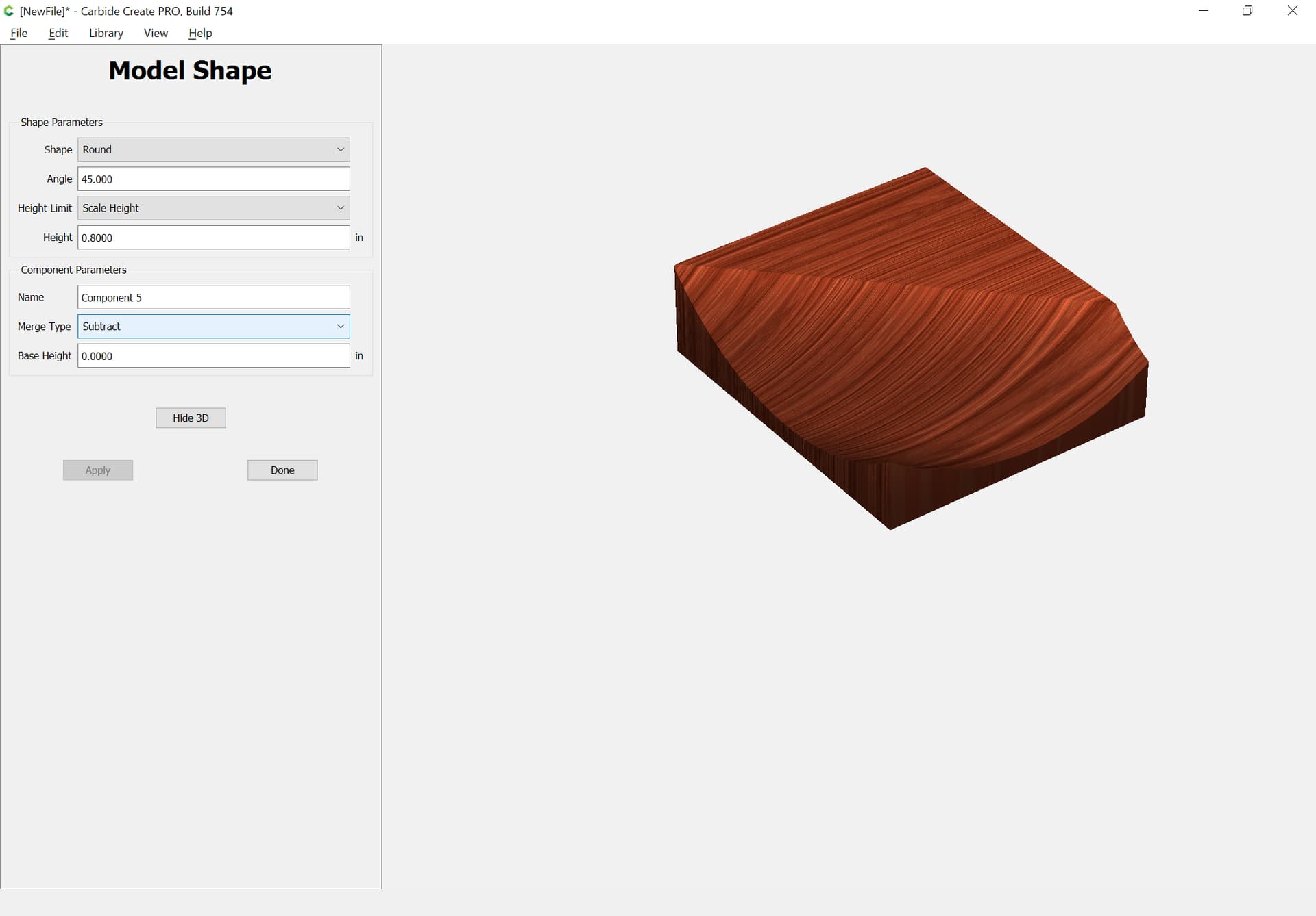
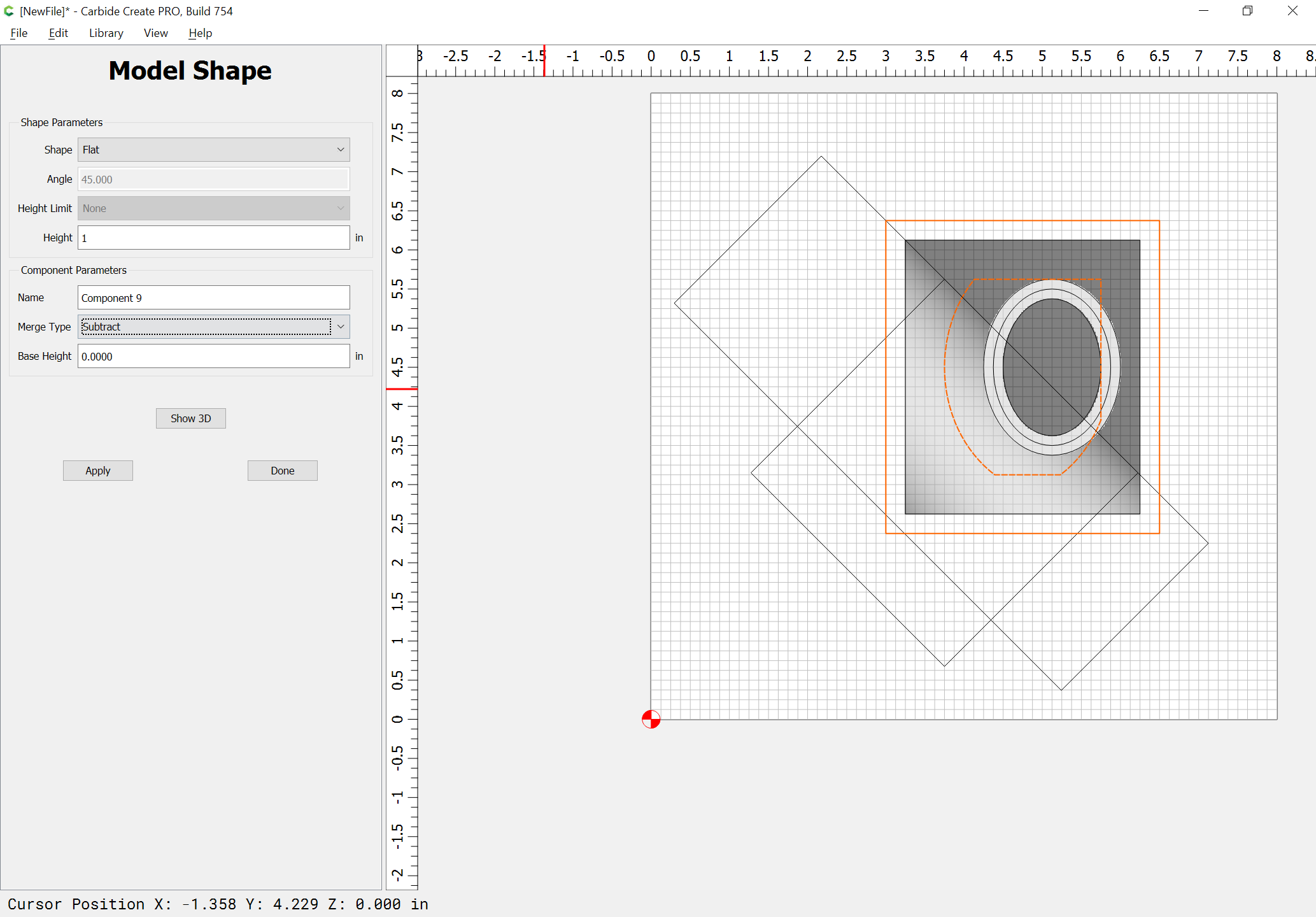
Then subtract the rounded form:
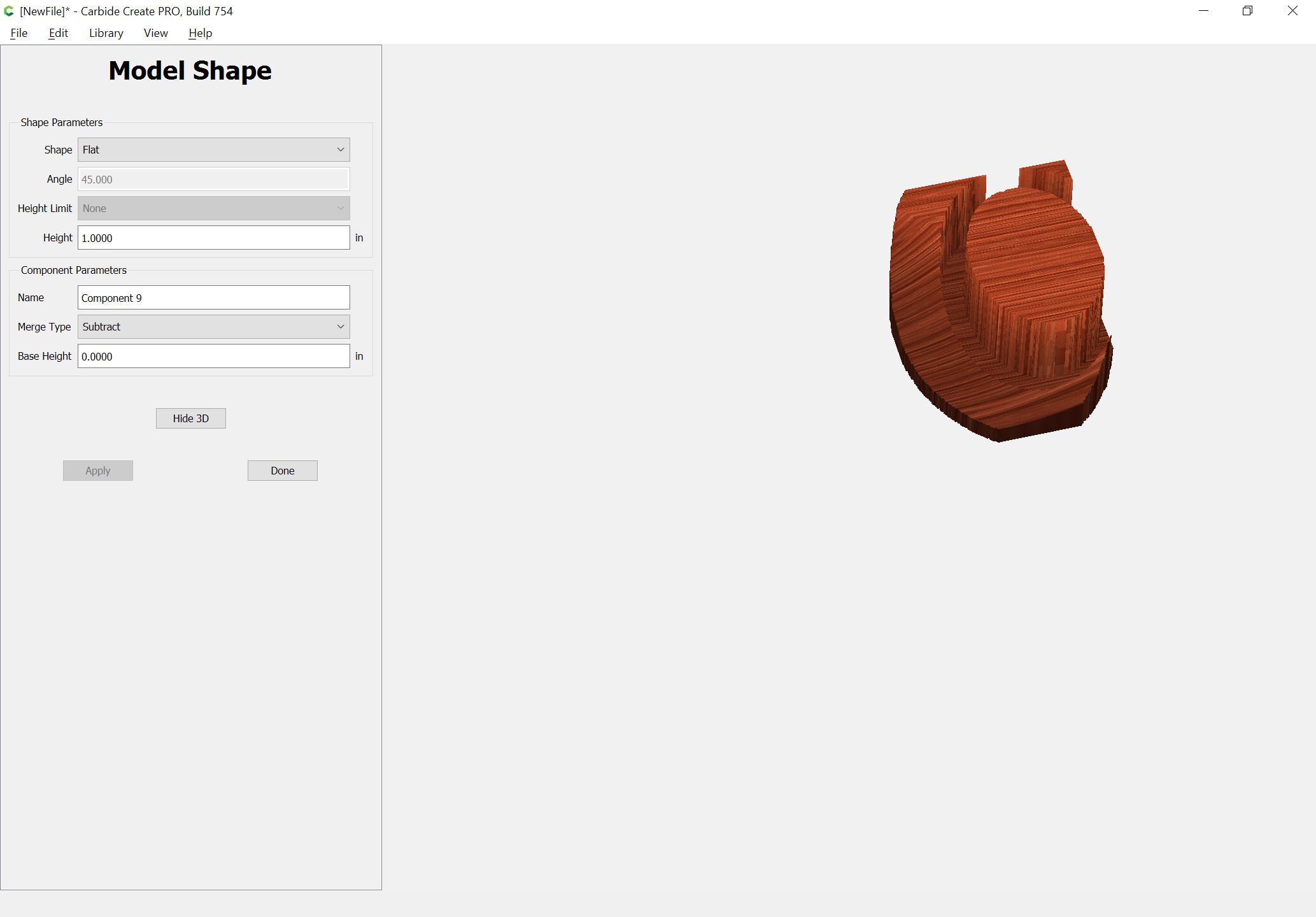
Then use the balance of the geometry to force the desired heights:
(and adjust ordering as necessary)
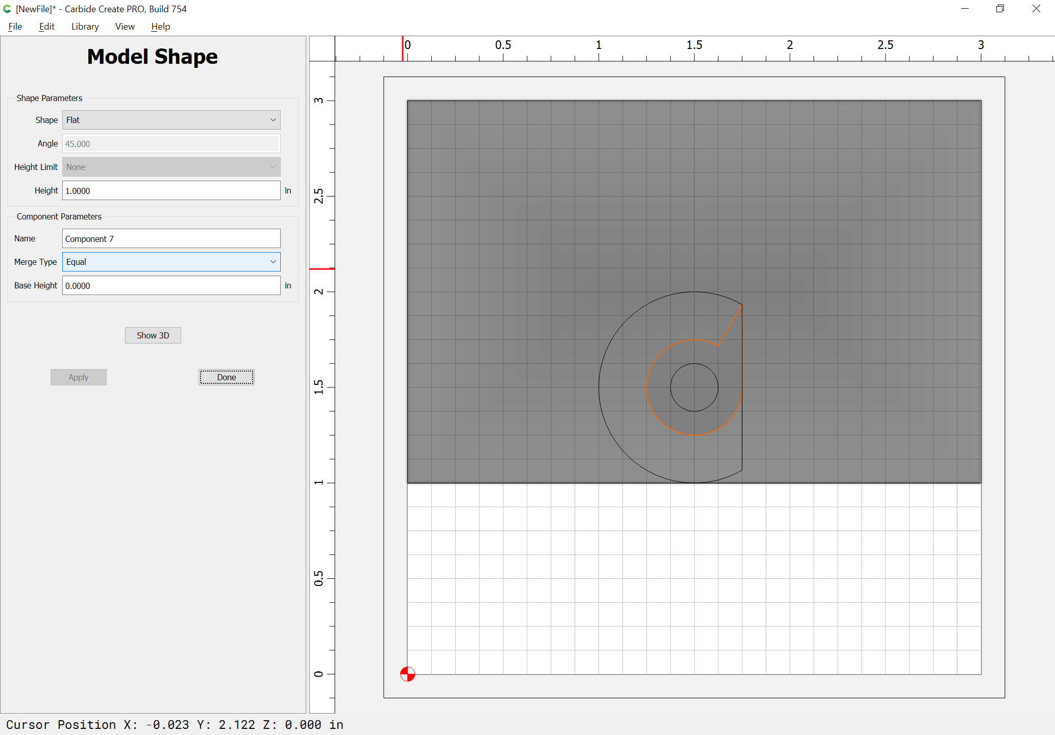
and then add geometry to trim away anything which isn’t wanted:
Obviously the drawn geometry doesn’t quite match up with the intent, but that should show the techniques necessary to arrive at it if given complete dimensions and so forth.
One further concern — the cut part seems to show an undercut — this can’t be modeled in Carbide Create Pro, but one could use the Keyhole toolpath to put it in.
Did the user supply any other information? Looks like the tapered surface is a ramp to me.
I just made something similar in NX, and had pondered how to make it in CC. (A camlock)
No, that was all — a DXF and a side profile drawing would have helped a lot.
Tapered would be easier:

I have nothing constructive to add, but I’m impressed. Does CCpro build/interpret 2.5D shapes by using gradients?
Hey, nice!! ![]() Mine was a true helix, but this would work just fine. And the little triangle flat spots were really not necessary either. They just happened when I spun the line around the helix.
Mine was a true helix, but this would work just fine. And the little triangle flat spots were really not necessary either. They just happened when I spun the line around the helix.
Curious if the user’s piece has a similar purpose? Mine is for a clamp frame for a vacuum form tool.
William, Your instructions gave me the desired results. Thanks, mischief managed.

Please note that the solid red indicates that you have extended the model up above the stock.
It an addition slipup when calculating thickness.
This topic was automatically closed after 30 days. New replies are no longer allowed.