After the depth per pass didn’t seem to be being honored when doing a logo from image elevation cut I have gone back to using a standard stl that I generated from onshape.
My design has dimensions of roughly 1.15x1.15x1.15"
stock is 1.517" thick
max cut depth is set to 1.334"
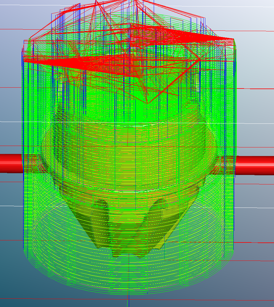
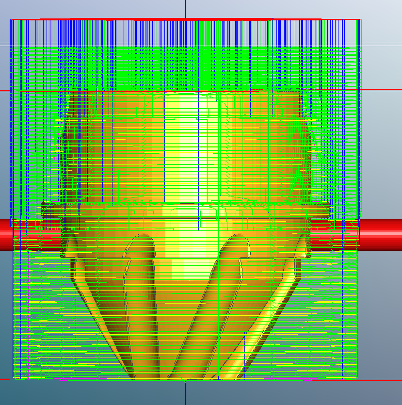
The problem is that when I set zero for the Z axis (touching off with a piece of paper for example) and begin the project the toolpath Z axis zero seems to be off by what appears to be .250 or so (the toolpath starts cutting in the air above the stock). Looking at the Meshcam toolpath this does not appear to be in the actual toolpath, is something not functioning correctly with my tool measurement or with the zero set perhaps? Attached are a few screenshots of the top toolpath that meshcam calculated.
From your description of the behavior, and eyeballing the side-view screenshot, it sounds like the MeshCAM Z zero is at the top of the geometry rather than the top of the stock. You could determine that from the first few lines of the gcode. Is the first cutting Z level (the first downward plunge into the material) a positive or negative value? If your MeshCAM Z zero is at the top of the stock, all cutting moves should have negative Z values.
Yeah, so the first place where I see Z is at line 13 and 14:
G1A0.000Z4.143F476.2
G1Z4.143F1905.0
Looks like neither of them are zero assuming this is the right thing that I am looking at. This must mean that there is a setting somewhere that I missed…
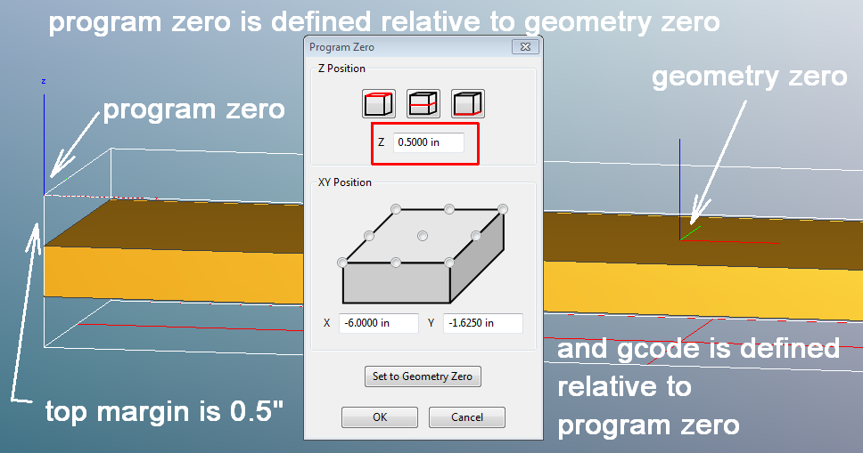
In MeshCAM what did you tell Set Program Zero to do? There is a “Set to Geometry Zero” checkbox, but everything else is relative to the stock. But be careful–in that dialog box the Program Zero is defined relative to the Geometry Zero. After that point, the gcode is defined relative to the Program Zero.
Oops, you replied while I was composing. It all depends on where your geometry zero is defined in the STL file. I usually arrange for the STL origin in my CAD program to be where I want the zero to be when I import to MeshCAM.
I’m still trying to wrap my head around what you are saying, but I think (due to the fact that the first cuts are, in-fact, negative on the Z axis now that this will do what I need. I’ll just have to test to be sure, thanks for the assistance thus far!
As long as the Program Zero XYZ marker (red,blue,green lines) is at the top of the stock (drawn in white outline) in MeshCAM, you’ll be fine. Like at the left edge of my screenshot above.
When you’re setting up Program Zero in MeshCAM, just click on the “top of stock” icon (top left corner of the dialog) and you’ll be OK as long as your physical stock thickness matches your stock definition in MC. Don’t worry about the numbers at that point. As in all 2-sided cases, you need to accurately measure your stock, enter the numbers in the Define Stock dialog and check “Lock Stock” so that MC doesn’t change them.