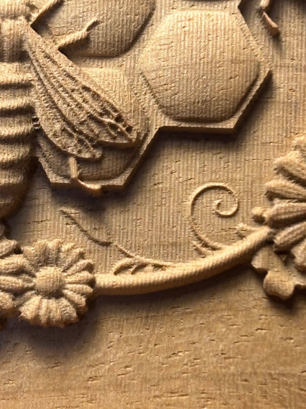
Still getting my legs with carving. I’ve sussed it’s best to do one rough pass with a coarse bit then a finish pass with a coarse bit followed by finer bits. In the photo below there are three finish passes. I’m using a Nomad, there was no interruption, such as re-zeroing, between passes.
Notice the grooves from bit 2 are still evident, I would have expected them to be milled over by bit 3. However, bit 3 did add more detail, to the naked eye the carving isn’t bad.
My Nomad has been very precise and accurate. This is quite a small amount, could this have been dust on the tip of the bit or bit setter? I do vacuum between bit swaps but not the bit setter. Any other advice? I’ll probably reduce the stepover for bit 2 next run.
Let me see if I can dig up some old posts regarding bit setter accuracy. I expected this height variation is coming from the tool length probing routine if you are running it for tool swaps.
(Quick disclaimer, I do not work for precise bits but I do recommend them and their products highly )
I could be misremembering but I think the precise bits folks will set depth rings for each of their bits so the tool length is consistent across tools. ( @TDA should feel free to correct me if that is not the case )
They also have a bunch of info on depth rings Reference and sell them if you want you install then yourself…but it’s not trivial to install them accurately with any diy approach I could find
It might be worth seeing if they have a few of your most common tools and asking if the depth rings are accurate enough to completely bypass tool length probing.
No tool length probing means your depth repeatability is entirely dependent on your z axis mechanics. If you still have trouble at that point and your machine is aging, maybe think about checking the wear on the Z screws anti backlash nut (two delrin pieces with a spring between.
This might be easy enough to test by just running a test pass, doing a “tool change” without actually removing your tool, and running the same test path again. It might be difficult to tell visually but you should be able to discern if you are cutting air, springing the surface, or removing material based on the sound of the cut.
Thanks for the feedback. I’m familiar with Precise Bits, they’re my choice for pearl. Plus they have great tips for feeds etc.
My best guess is that the play in using depth rings might be more than what I’m seeing here. The photo is enlarged, the depth difference is pretty small. Then again, my experience with depth rings is minimal, I usually clip them off on receipt.
I’ll try the test you mention when I get a chance.
Quick aside, instead of actually doing a cut you can just probe several times with the carbide motion log window open…obviously the tool length is stored so we might as well just look at it directly
You will see some lines with a PRB value like:
That last value of -84.x in my case is my tool length. So you can get away with just measuring your tool length a bunch of times and not cutting anything.
Note that this is going to give you the repeatability of the combination of your z travel and your bit setter. You can’t use this alone to measure your z repeatability.
Still, it’s much quicker than actually cutting something and it should get you in the ballpark. My variation is ~0.015mm across multiple tests which seems to line up with my expectation. I’m not surprised anyway
…I really want to write up a little gcode file to automate this testing now.
What specifically do you mean by probing? I’ve seen this referred to but haven’t done it. Isn’t this something that requires feedback from electrical contact?
Measuring on the BitSetter is one type of probing.
More sophisticated machine can also probe the material to determine its location. C3D’s version of that is the (somewhat simpler, somewhat more restricted) BitZero.
Internally, they are all being done by the controller (not CarbideMotion), and they are all generically called ‘probing’.
So, in light of what Michael wrote, you would grab these values from simply measuring the bit length on the Nomad?
BTW, I did another run with a denser wood and a finer stepover for bit 2, don’t see any grooves or evidence of the bit 2 pass. So perhaps the first run was at the limits of precision as shown in your example. It’s quite possible those grooves are within the 0.015 mm as in your example.
All in all just my curious pursuit of perfection, still happy with the results.
Usual preface, I’m with PreciseBits so while I try to only post general information take everything I say with the understanding that I have a bias.
Generally speaking we set rings to the spec in your “Reference” link (±0.004"). However, that is across multiple setups on different days. Typically in any given set of tools on the same day it’s about half that. We will also do custom tolerances if there’s a need.
**All the below assumes that you are using ball-nose correctly sizes and no mechanical issues.
That being said I doubt that’s the issue here. For a perceived “smooth” surface in a 3d carving you need no more than 10% stepover with everything being perfect. In most cases things are not perfect so most shops that regularly do 3d carves have a finishing stepover of 8% or less. Although groove height is proportional to the diameter this still applies.
Typically in shops that do a lot of these, any tool change is done either with stickout references (depth rings, tool-holders, etc.) or tipping off at the same uncut section. For many they are zeroing off the base or waste-board and not the material being cut as there’s also some issues with wood warping when a lot of material is taken out of it due to internal and/or surface stresses.
A few things not related to depth or stepovers settings.
Don’t have enough coffee in me yet to work my head around the numbers… But are all 3 of those passes being done at the same depth? In most cases best practice would be to do the first “rough” or “clearing” path. Then the finishing with a slightly deeper cut depth to give enough material for the bit to “grab”. If using a 90° or other angle offset to pickup some of the details that get missed it would be at the same cut depth of the original finishing pass.
I don’t know what version you are using. But one thing that we usually recommend is doing 3d carves in a “offset” or “maze” path (from the center out). Raster paths generally have more errors, and they are more noticeable, especially if the material shifts or warps even slightly.
That’s all I can think of off the top of my head at the moment. Hope it’s useful. Let me know if there’s something I can help with.
Thanks for the detail! I’m using Carbide Creat Pro, I don’t have choices on how the carving passes are done path-wise, it’s all raster. As far as tipping off again for each pass, I very much doubt I can do that repeatably within the range of discrepancy here.
I only set the depth once which applied to the rough cut and all three finish passes. In CC Pro, you can specify Stock to Leave for the rough pass which, I think, maybe equivalent to your suggestion of leaving material for the bit to grab.
I re-ran the carving again in a different wood at slightly greater relief but with a sizably smaller stepover for bit 2, about the 10% you mention. The results show no grooves from bit 2. Under greater magnification I see the micro grooves from bit 3 so I suspect it was bit 3 doing its job completely versus the finer stepover of bit 2. (Yes, my education is in science yet I still change multiple variables at a time!)
My conclusion is that Tyler is likely correct in pointing out a micro amount of tolerance in the bit setting although I’ve yet to probe that myself.
The probing variance is a possibility, but in general, it’s always best to make sure that there"s something for an endmilll to slice into. Multiple finish passes leave very little for a cutter to bite into. Unfortunately, there’s no “stock to leave” option for a finishing toolpath in Create (only roughing), but a quick and dirty workaround might be to deliberately leave a “chip” on your first finishing tool. Aka stick a piece of paper between the tool and the tool length probe.
Also, I don’t think you really need to do a 3-stage finishing. To me that seems excessive. Lets say there’s a pocket of material your first cutter missed. With your finest bit, the most you’ll ever cut into material is your stepover. A 0.5mm bit ought to be able to handle cutting into 0.1mm of material. I think you can save yourself quite a bit of time.
Thanks! I’m still on a learning curve with 3D. This is my first trial with three passes, I resorted to this because bits were breaking. I worry less about taking material off relatively horizontal surfaces than encountering the more vertical areas with these tiny diameter bits with long reaches. For example, the 0.508 mm has a reach of 3.0 mm. I ran another trial with the same bit regimen but with about 10% more delta Z, the #3 bit broke and stuck in the wood in a spot with a deep pit.
One reason I introduced the third finishing pass, the coarsest one, was to save time by using a coarser roughing bit.
Supposing I want to finish with the 0.508 mm bit, what would you recommend as the first finishing bit? Omit bit 1? ( I was using a 1.0 mm bit with 1.50 mm Stock to Leave for a rough pass.)
I’ll try the “chip” strategy. So, is the theory behind “leaving something to cut” that if there’s too little bite the substrate will depress versus cut?
In wood, it’s not super critical to form a chip, but it still helps. In metals, ultra shallow cuts can cause the cutter to skip/grind at the microscopic level instead of slice cleanly. In wood, you get to a point where the tiny point of your cutter is just swirling against the fibers, dulling itself while accomplishing very little useful work.
Generally, I think the smallest bit I’d use in wood to “pre-finish” something is 1/16". And for stock to leave, I like about 0.2mm. If you’re still seeing machining marks left from the roughing pass, maybe bump that up to 0.3, 0.4. The machine’s margin of error ought to be much smaller than that.
For super fragile AND deep cuts, it may be worth looking into a tapered ball endmill. It won’t work if your design has super steep vertical walls. But even if it does and you’re okay fudging it a bit (it’s usually not noticeable anyway), a tapered endmill is fragile only at the very tip and gets exponentially stronger quickly as its height rises.
Also, personal preference: Do your finishing passes with the grain of the wood. Visually, it’s much easier to hide or overlook imperfections.
To make this a bit easier to understand I ran off some quick images for this. These assume that you have true “ball” ends but here’s what the remaining material looks like on you 0.889mm with a 0.30mm stepover.
So, there’s a couple things to take away from this.
First, assuming that 0.015mm number is accurate you can't really do anything with a 2nd finishing tool reliably. So I'd throw that out.
Second, unless you need the smaller tool to reach into something, you could get a smoother surface just running the 0.889mm at the 10% stepover. If you were trying to clean up curves you could run it a 2nd time with an offset angle keeping the same zero.
In terms of breaking tools it depends on how the software handles it. But most times where you get into trouble is where the the finishing tool can reach into somewhere that’s completely untouched by the previous tool. If it tries to use the same settings as the rest of the finish it will slam full depth into uncut material. That will be a radical increase in cutting forces. Some software will see this and let you take multiple passes at the previously untouched area. I don’t know CCs method for this.
Yes, all of your finishing need to be the same bit using your allowance to actually cut. At this level you can’t reasonably get a second bit to cut at a “same enough” Z (again assuming the 0.015mm number is correct). Keep in mind though that as you will functionally be increasing your stepover (at some points) and pass depth for the 0.889mm tool you may need to adjust your feed/chipload.
There’s another option here if the software will allow it. You could do 2 roughing passes with the 1.65mm and 0.889mm bits. Have the same allowance on both with enough to cover the 0.015mm plus some for an actual chip. Then do a single finishing with the 0.508mm tool. This would let you remove at least a similar amount of bulk material with each tool while leaving enough margin to allow the 0.508mm tool to finish properly. However, this won’t do much with the angle offset, and will still be a bit harder for the 0.508mm tool than if it was cleaning up at the same Z. This will make it a lot easier for the 0.889mm tool. Although, if the 0.889mm tool isn’t having issues cutting without the rough from the 1.65mm, the 1.65mm is just a waste of time.
After three more trials with better results, I’m thinking the first was somewhat of a fluke. For my last trial, a keeper, I applied some of your advice.
I upped the rough pass stock to leave to 0.20 mm. But the best change was using your suggestion of inserting a shim (“chip”) during bit setting for the penultimate pass. I could see more material being removed compared to a static zero. Results were great.
Yeah, I usually finish with the grain in wood although most of my 3D work so far is in grainless plastics where I finish to conform to natural ones in the design.
Thanks again, especially the suggestion of getting some bite for subsequent passes. I used that in conjunction with Winston’s method of “chipping” the bit-setter and it will become part of my MO.
I’m using Carbide Create which doesn’t allow the equivalent of rest machining on rough passes so subsequent passes would involve a lot of cutting air. From my forum perusal it seems the accepted paradigm is for one rough pass.
One of the reasons I was using 3 passes is that most of my bits are sub millimeter. I’ve got some 1.14 mm bits on the way which I will try subbing for the first two finish passes.
Final pass step over should be around 10% of the bit. ie .if I use a .016 bit I use a .009 step over, or a .125 bit I set at .0125. I find this to produce a much smoother finish with almost invisible lines.