I have had a Shapeoko PRO for about 9 months. I have struggled with frequent “disconnects” where the machine just freezes instantly in the middle of a project and gives error messages like “Cutter Not Responding.” I can always restart the machine, reinitialize it successfully, jog back to my original tool path zero point and continue the project. I have learned the hard way to accurately mark my zero point so I can restart projects as accurately as possible. It has not uncommon to have to restart a project 1-3 times.
My system includes the following: Shapeoko Pro XL wired to a separate electrical circuit in my home. Carbide Compact Router. Dewalt Shop Vac with a Dewalt Separator and a wire reinforced dust collection hose all grounded to my wall panel. My Shop Vac and the Compact Router are powered on a separate electrical circuit. I use the supplied USB cable to my computer with a USB Isolator that I purchased.
After previously working with tech support (great people) and after researching the proper grounding of a CNC machines, I finally started checking the grounding on my machine with a quality voltmeter. I checked for “continuity to ground” at multiple points on my system only to find multiple irregularities. My assumption is that the resistance readings for “continuity to ground” should be as close to 0 Ohms as possible and definitely less than 3-5 Ohms on a sensitive piece of electronic equipment like this. To my surprise I found many points on my X axis, Y axis and X/Z assembly with reading as high as 30-50 Ohms and some points with no continuity at all. There was also no continuity to the outer metal of my router through the black powder coating on the router mount. I had perfect continuity to the reinforcing wire on my dust collection hose and to my shop vac so that was not the problem
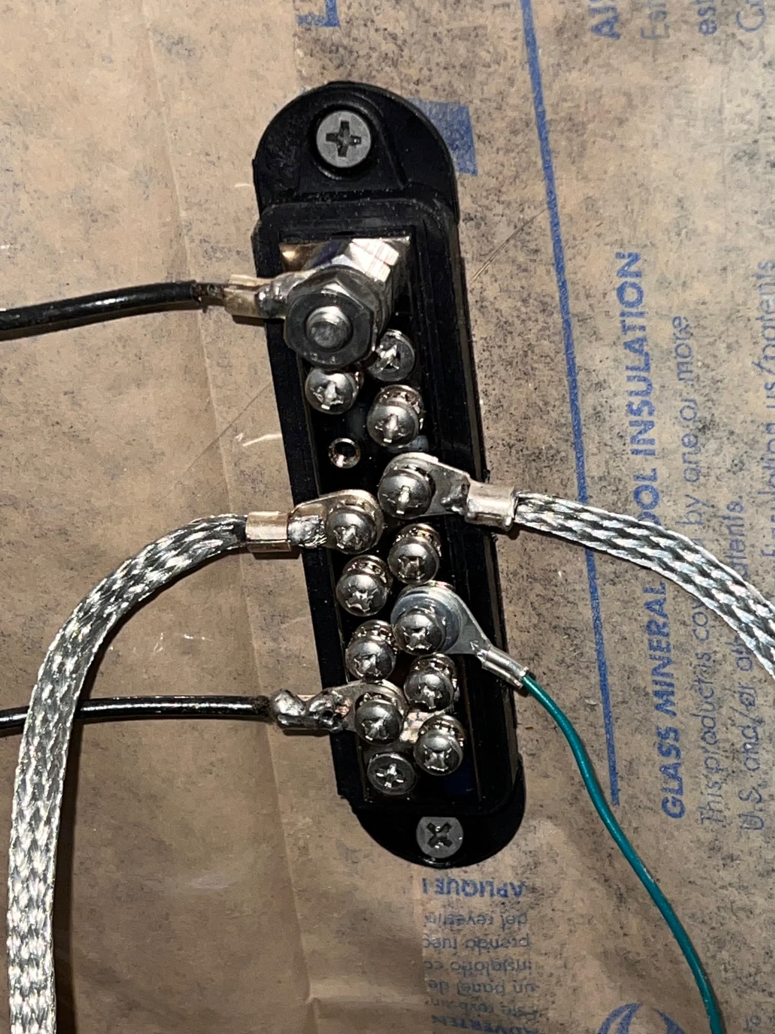
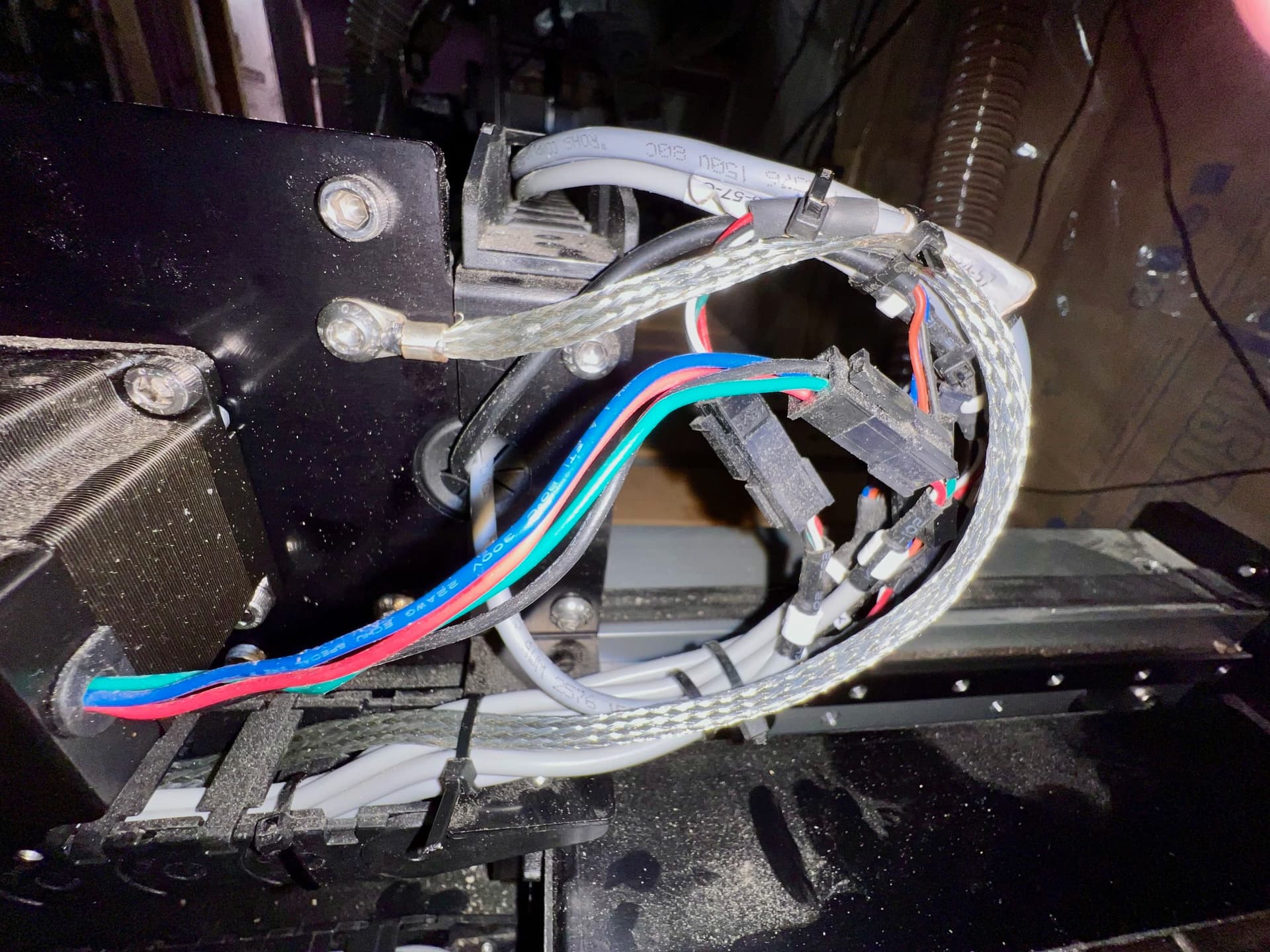
I decided to install a separate star point grounding panel on the adjacent wall with a grounding busbar (Amazon). I will attach a photo of this busbar plate. I then soldered a heavy grounding wire from my wall outlet to the main outlet on the busbar plate. Then I attached separate ground wires to each component of my CNC machine back to this plate. I used flexible tinned flat copper braid so that I could thread it through the drag chains on the machine to get direct and reliable connections to both the X and Y axis. I attached the controllers green ground wire directly to this plate instead of to the CNC frame. I attached ground wires from my dust collection hose to the plate as well. I also sanded off the black powder coating where needed to get good continuity throughout the X/Z assembly and the router mount to get good continuity throughout this assembly including to the outer surface of my router.
Now when I check for continuity with my voltmeter, I get reading very close to 0 Ohm everywhere on my machine. So far, it seems to have worked. For the last week, I haven’t had a single disconnect which has been a revelation.
I am no electrical engineer but my conclusion is that the grounding on these machines are very inconsistent and not what is required for consistent operation in many situations. Fortunately, it seems to be pretty easy to fix with a better plan for grounding. I would like to hear other opinions. These seem to be common problems. Unfortunately, I had to figure most of this out on my own on the internet with a fairly significant alteration of the machine.