My new Shapeoko 3 won't cut a straight line

@MervynMitchell,

Do you mind explaining this jig, while we wait for your v wheels to arrive?

I think I understand the concept behind it, but I am not sure about how you use it.

Thanks

P.s. I get it now! I looked at it a bit more. So when you spin the V wheel it will move the wood when it comes across a bump or depression.

The V wheels I’ve ruined have enough physical damage, that I can see the damage.

1 Like

To start with - Liam - I think the design must have changed recently. My wheels look like David’s but they only carry a single shim (about 1 mm) mounted on the inside of the V wheels (ie. against the beam). I’m assuming this is intended and not an omission at the time of assembly, since the wheels run smoothly, and I cannot see how this might contribute to my problems. The V wheels on the Y beams also only carry single shims and there is no detectable waver when cutting straight lines in the Y direction.

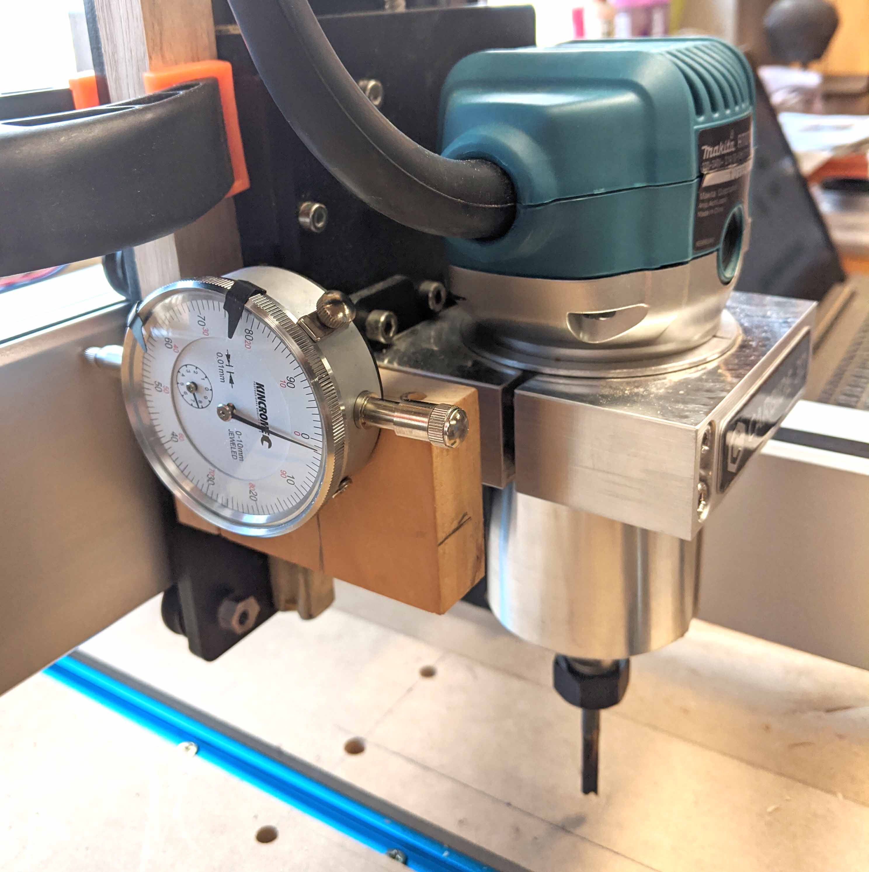
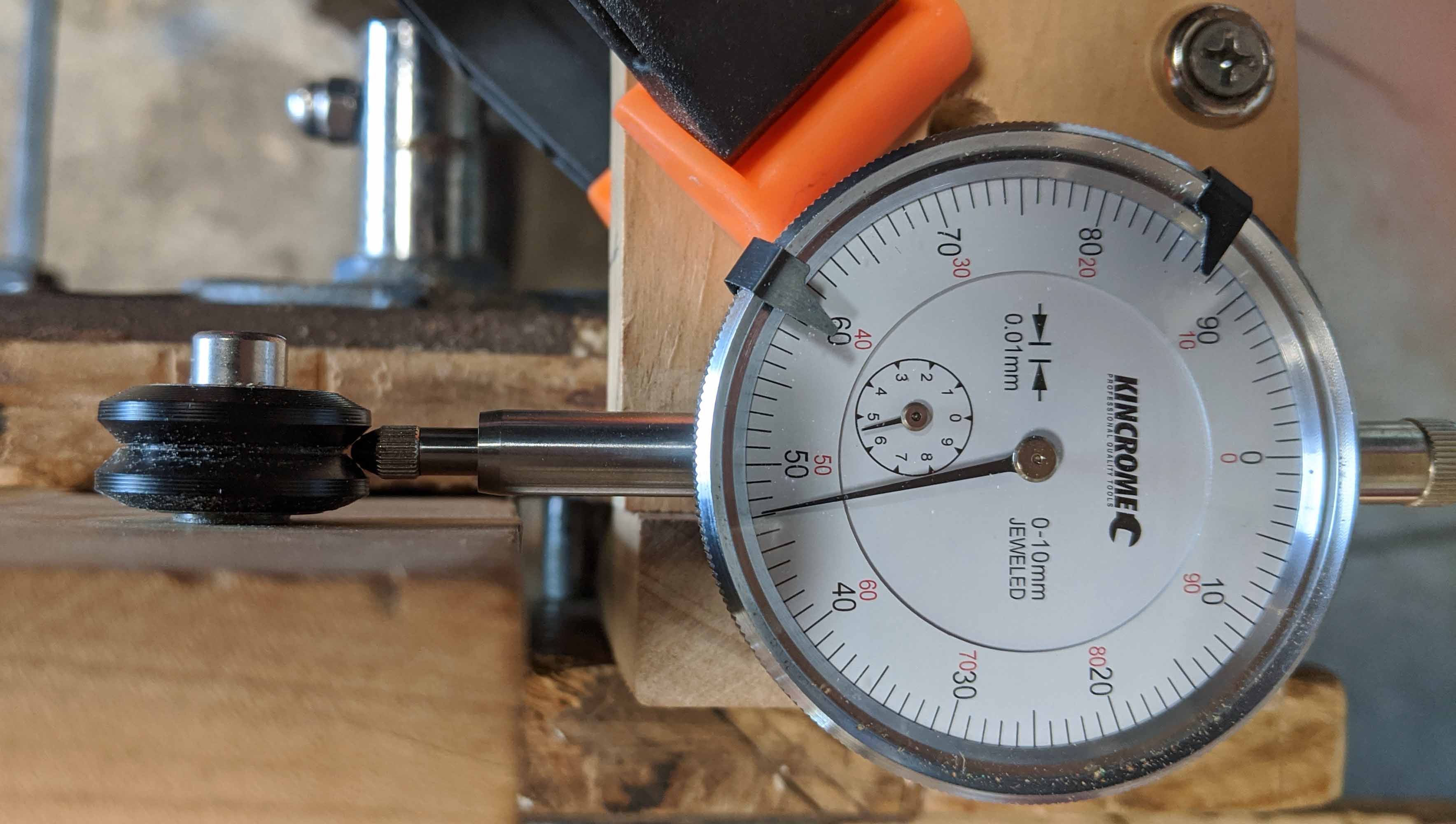
I’ve pretty well narrowed the cause of the waver down to the four V wheels that secure the router carriage to the X-beam. When removed and rotated with a dial guage (calibrated to 0.01 mm) bearing on the center of the V slot, the variation appears to be between 0.08 mm and 0.2 mm when measured over the four wheels. This doesn’t sound like much, but appears to arise from deformation of the wheel causing the plane of the slot not being exactly perpendicular to the axis around which it is rotating. Does this make sense? The mechanical arrangement could cause these irregularities to be magnified at the cutting end by a factor of about 2X, leading to the roughly 0.5 mm waver I’m obtaining in my straight line cuts (ie +/- 0.25 mm).The apparatus I constructed is pretty crude but gave fairly consistent results over multiple measurments (see below)

When I mounted the dial guage on the router carriage (see below), the gap between the top of the beam and the router carriage varied by 0.1 mm as the carriage traversed the length of the beam, reaching its maximum value five time over the 16" traverse.

Again, this would seem to be sufficient to cause the waver I’m observing.

The only explanation I can obtain from this is that the X-axis V wheels are deforned to various extents, although the 7 cm period of the wavers (also the circumference of the V wheels) suggests that one is more deformed than the others and I observed that the upper left wheel is worse than the other three.

One question remains - did I cause this or is there a manufacturing flaw. I actually undertightened the wheels at the ouset, rotating the cam screw only until the first resistance was encountered. I later noticed some slop, and tightened just enough to eliminate this.

However, if these wheels were faulty at the outset, mine would not be the only machine to have experienced these problems and others surely would have contacted Carbide-3D.

I’m about 95% certain this is the root of the problem, but would still value anuy other suggestions.

Either way, I’ll buy a new set of wheels and concentrate on my garden while waiting for them to arrive - Spring is just around the corner.

Thanks everyone for your suggestions and I hope you are all keeping happy and healthy in these trying times.

Mervyn

Tasmania, Australia
4 Likes

The wheels are turned on a lathe — we’ll gladly replace these, just let us know.

3 Likes

The other shim should be inside, sandwiched between the 2 bearings.

Did you Swap the questionable wheel onto a y-plate, and put a “good” wheel onto your x-plate? It should cause Less of an issue When mounted there, as there isn’t really an opportunity to induce camber, thanks to the x-rail.

Honestly, I wouldn’t put much more thought into how or why the wheel is the way it is, it just is. The wheel itself is a consumable item, and a cheap one at that.

Carbide3d team is top shelf, and they will get you up and running.

3 Likes

Good measuring, it looks like you’ve eliminated everything but the cause of the fault.

The periodicity of the measurement still seems to be the strong pointer here.

The lack of shims is interesting, if your wheels look like @David.Curtis but have no internal shim then either the shim is missing or, as you say, the design of the wheel has changed. As I understand it the purpose of the shim between the inner races of the bearing is so that when the clamp bolt is tightened the inner races are locked into a fixed relative position in a solid stack from the plate to the bolt head. This then fixes the outer races on the plastic lip between the two outer races. This reduces any unwanted axial movement without creating excess axial load which the bearings aren’t meant to take and quickly causes wear.

Presumably the new wheel has either a much narrower gap between the bearing outer shells or is fitted with a differerent bearing? (although even an angular contact bearing normally needs a fixed spacing)

It would be good to confirm the lack of requirement for the shim.

It might also be worth checking your bearings for axial play and slack?

1 Like

Hi William,

As requested in my email to Carbide 3D yesterday, could you please supply a set of V wheels for the X beam. I’m happy to pay for them – you should still have my Visa details already on hand. Perhaps send them by the fastest method of getting to Australia – maybe courier (Fed Ex managed to get the Shapeoko here within 7 days of the placement of my order with you folks). International mail in and out of Australia is moving at a snail pace at present.

Many thanks,

I’m afraid your e-mail was addressed to a person who doesn’t usually work weekends.

It should get answered during business hours Tuesday.

I also edited your post to remove your address — we don’t want personal information here on the site due to privacy considerations.

2 Likes

Thanks everyone for your advice and concern. Carbide have sent me six new V wheels which have solved my problem. My machine now cuts straight and I’m a very happy chappie!

10 Likes

This topic was automatically closed 30 days after the last reply. New replies are no longer allowed.