I have a new Shapeoko 3 which works wonderfully well except for one important fault - it will not cut a straight line parallel to the X axis, no matter what type of cut I am making - pocket, straight line, profile etc. Correspondence with the folk at Carbide 3D has suggested I check all mechanical issues, which I have done, but the fault persists. The pulley set screws are firmly in place against the flat sides of their shafts, the V wheel tensions are correctly adjusted and the X and Y drive belts seem evenly and correctly tensioned. I am cutting at the speeds (RPM and feed speed), depths per cut and stepover as recommended on their website for the wood and cutters I am using. The machine is square and level and the wood I am cutting is securely fastened.
Since checking all these, I have made a number of long 4 mm deep straight cuts on 16 mm MDF using the #201 ¼” end mill at 18000 RPM and the recommended speed, depth per cut and stepover. There is significant wander on cuts parallel to the X axis, less but noticeable wander on a 45 degree diagonal cut, and cuts made with a constant X value (parallel to the Y axis) appear to be straight. Deviations from linearity are between 0.5 and 1 mm. I’ve sent photos and the G code files to Carbide but as yet received no response.
Until this is sorted, I can undertake no serious work. Can anyone suggest a solution?
I suspect we’re going to try to rule things out, even if you’ve already tried it… but be patient with us, we don’t know what you already did.
the first thing to check is, with the machine on, but router off, try to wiggle by hand the bit in the router (careful, those are sharp so wear gloves or grab it by the non-sharp parts)
there shouldn’t be play in this unless you put extreme forces on.
(also when you say “with the recommended speed etc”… numbers speak… for but 201 I’d say 0.04" DOC at 50IPM)
You mentioned you see the issue when the cut is along the X-Axis, and less noticeable when Y and X are moving. This leads me to believe there is something wrong with your X/Z axis. Have you looked at the V-Wheels? I have seen in other posts where a V-Wheel is broken or cracked but is not noticeable until you look clearly at the wheel. Take them off and make sure everything looks good.
Maybe I misunderstand, but where are you measuring this deviation from? Edge of stock to edge of cut? Pictures help.
A possible cause is that your stock isn’t perfectly square to the x-rail.
Is your x-rail perfectly square to your y-rails? If your machine is slightly racked, this could happen. When you jog all the way forward, are both your Y plates the exact same distance from front rail? If not, your gantry is racked and needs to be reset.
When cutting parallel to X-axis the only motor in action is the X-stepper. The Y-steppers are locked, so any cut you make “should” be perfectly parallel to the X-rail.
Thanks guys for your suggestions. Taking your various points:
David, I’m measuring the deviation from a metal straght edge placed against the cut. The deviations from lineraity are especially noticeable when the cut is viewed from one end, sighting down the cut line.
I discovered a slight looseness in one of the lower V wheels on the X rail. Tightening this made no difference. I have been reluctant to overtighten for fear of breaking/distorting these plastic wheels. I’ve checked the four V wheels that run on the X rail and all are running smoothly and truly (without wobble) and none appdear to be cracked or out of shape.
The line wavers with a period of about 70 mm (every 2.75") (which suggestively is roughly the circumference of the V wheels and the notched X drive wheel).
If I clamp a metal straight edge parallel to the X axis so the bit just kissess it at both ends, and then use the X+ jog function to move the bit along the rule, I can see a small gap open up at roughly 70 mm intervals (in a positive Y direction - of course, with the router turned off!). There is no perceptible slack or wiggle when I attempt to twist or tilt the router and Z axis assembly, but I suspect the router is tilting slightly forward and backward as it traverses the X rail. But I can neither see nor think of any reason as to what is causing this. There is no perceptible wobble on any of the X axis V wheels, nor the belt drive wheel or the two wheels that deflect the X belt upwards. Of course a tiny amount of tilt would be magnified at the cutter end but for the life of me I cannot see what is causing it.
The Shapeoko 3 was assembled exactly as described, and worked immediately. I’ve checked the machine over and over and racked my brains for many hours over three days!
I’m hoping someone smarter than me can spot the problem. I live in remote rural Tasmania, far from expert assistance!
I would take the Z axis completely off the gantry, pull all the v-wheels from the carriage and inspect them separately. Roll them on smooth surface to check for out-of-round bearing holes.
Have a look at the X axis stepper motor shaft when it is running to if it has a wobble.
What router are you using? Did you get the precession collars with it? Reason I am asking, it looks like you have runout. As stated above if using a 6mm cutter in a 1/4" collet you will have some play or the bit will be sitting cocked and not cut true.
Also looking at the photo your Z assembly looks like it may be loose. Going from back to front the Z has pressure holding it steady so you get a smooth cut. Once you go left and right you have play causing the cut to skew. Look at wheels, make sure the clamp that holds the router is tight, v-wheels are adjusted properly, v-wheels mounted to plate properly (washer in the correct place).
I see! The fact that you say 70mm, it has to be a v-wheel, as that is the effective circumference of a new wheel on a rail. (It rolls ~70mm per revolution when seated on the rail)
As others have posted, it could be a wheel with bearings not seated properly, could have a machining flaw. Something is leaving 1 wheel not true.
Edit: the repeatable position of the deformity is interesting to see. It should be easy to find your flaw based on that, roll to halfway between those deflections, and then check the exposed wheel surfaces. You should be able to see the defect.
Did you by any chance order the maintenance kit with your machine? If you had a spare v-wheel you’ll be off to the races when you find your gremlin.
When you’re taking v-wheels off to check, reverse your eccentric nuts straight up to slack position before unbolting anything. When reinstalling, use some loctite and make sure you don’t lose that little devil of a shim that goes between v-wheel and plate, it makes sure your inner race is the only contact point. Without it, your wheels are seized when fastened.
If your machine is a belt drive Z axis, you might have a broken wheel behind the router mounting plate. Some V wheels don’t look broken because they split in half at the deepest part of the V groove. I had this happen and it was a wheel that I could not see, until I took of the router and the router mounting plate off and inspected the 4 V wheels that are hidden from view.
Thanks everyone for your ideas and suggestions. Taking the points separately:
I’m using a brand new Makita router with the appropriate mount which locks it securely in place - also precision collets supplied by Carbide 3d. It definitely isn’t run out becuase when I use a single straight flute cutter and jog the machine in a +/- X direction, with the router off and the router bit touching a straight edge clamped to the wateboard, I can see a tiny gap open up between the bit and the metal edge roughly every 70 mm, whch strongly suggests the whole Z assembly is tilting very slightly forwards and backwards (in a Y direction) as it traverses the gantry. Any such movement would be magnified down at the business end of the cutting bit.
All this, as you have observed, suggests one of the X axis V wheels is out of true. By observing each one closely as the carriage moves, I can see no wobble or deformity, but this might not mean very much… I have slackened each weel off slightly and notice that the right hand lower front v wheel seems to bind at one point as it is rotated against the extruded track. I’ve now removed it and mounted it separately so I can observe it rotating close up. There seems to be no visual defect but this afternoon I’m borrowing a dial gauge to check it more accurately.
I’ll keep you posted. Assuming you are all from North America, I should mention that our clocks are 17 hours ahead of yours which rather slows down my response time.
David - you mentioned " that little devil of a shim that goes between v-wheel and plate". In removing two of the V wheels I did not see a shim - just a single 1mm thick washer between the wheel and the gantry. Is that what you were referring to?
BTW, being a new machine, Z axis movement is achieved via a lead screw and not a belt.
As you say, suspicion definitely falls upon the circumference of one or more of the V Wheels. When my machine has sat for a while there is a notable “bump” as the V-Wheels roll through the small dent that has formed in the wheels as it sat still.
If you put your finger across the gap between the Z plate and the X rail at each of the four corners in turn and them manually slide the Z left and right on X you may well be able to feel which corner is moving in and out against the rail. You may also be able to feel the run-out on the wheel itself.
If you’re borrowing a dial gauge, with a mag base, then attaching the base to the Z axis and putting the tip of the dial gauge on the X beam is a good way to look for movement as you move the Z left and right.
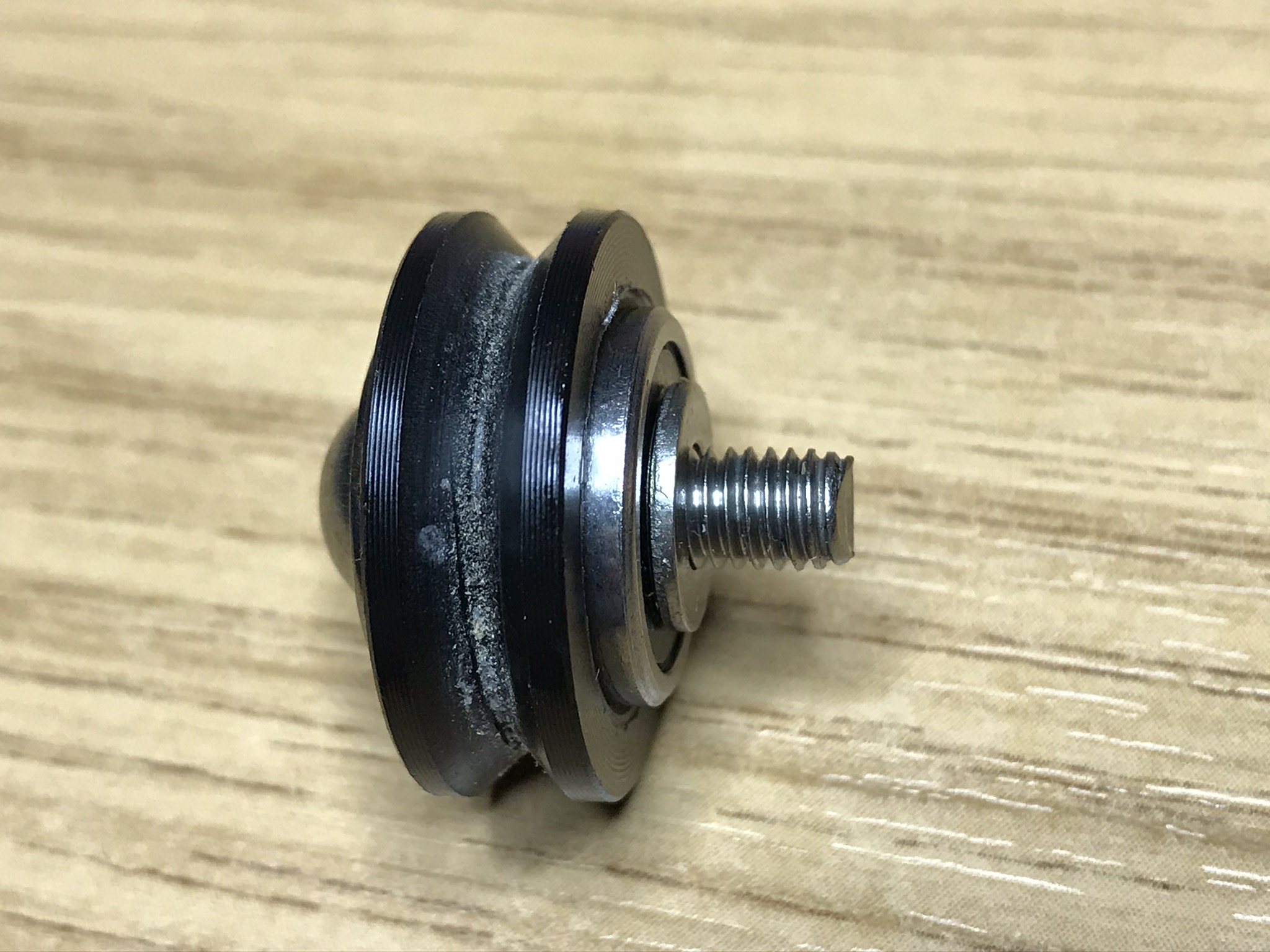
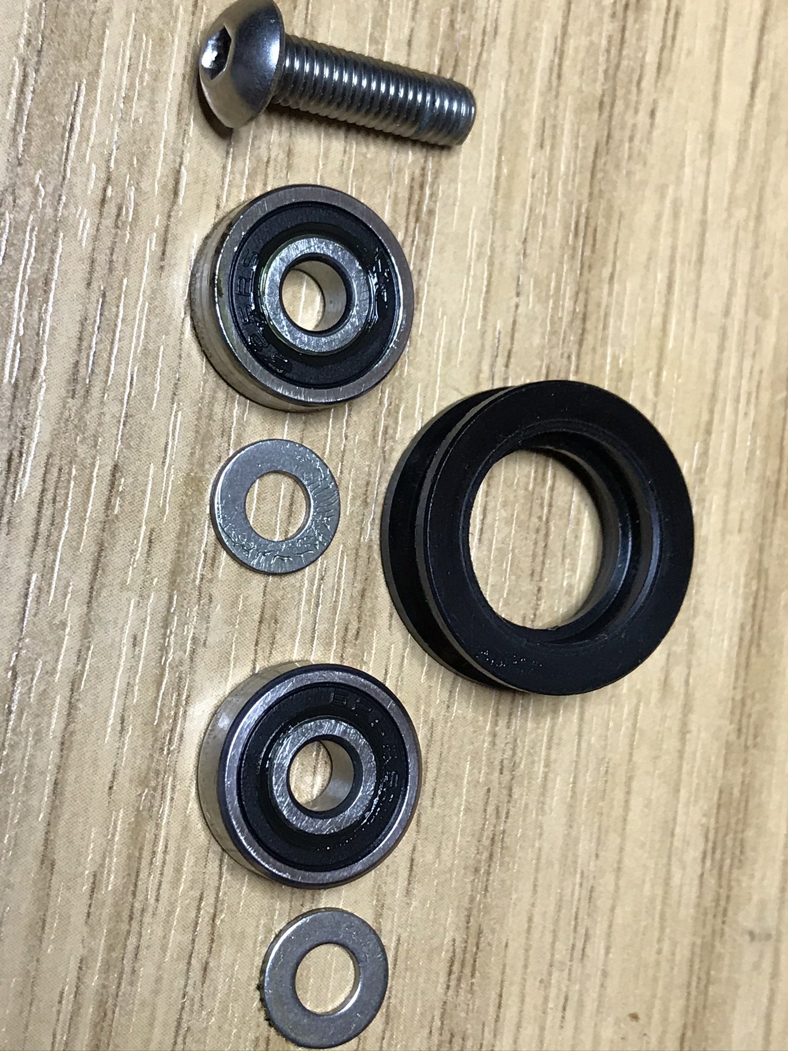
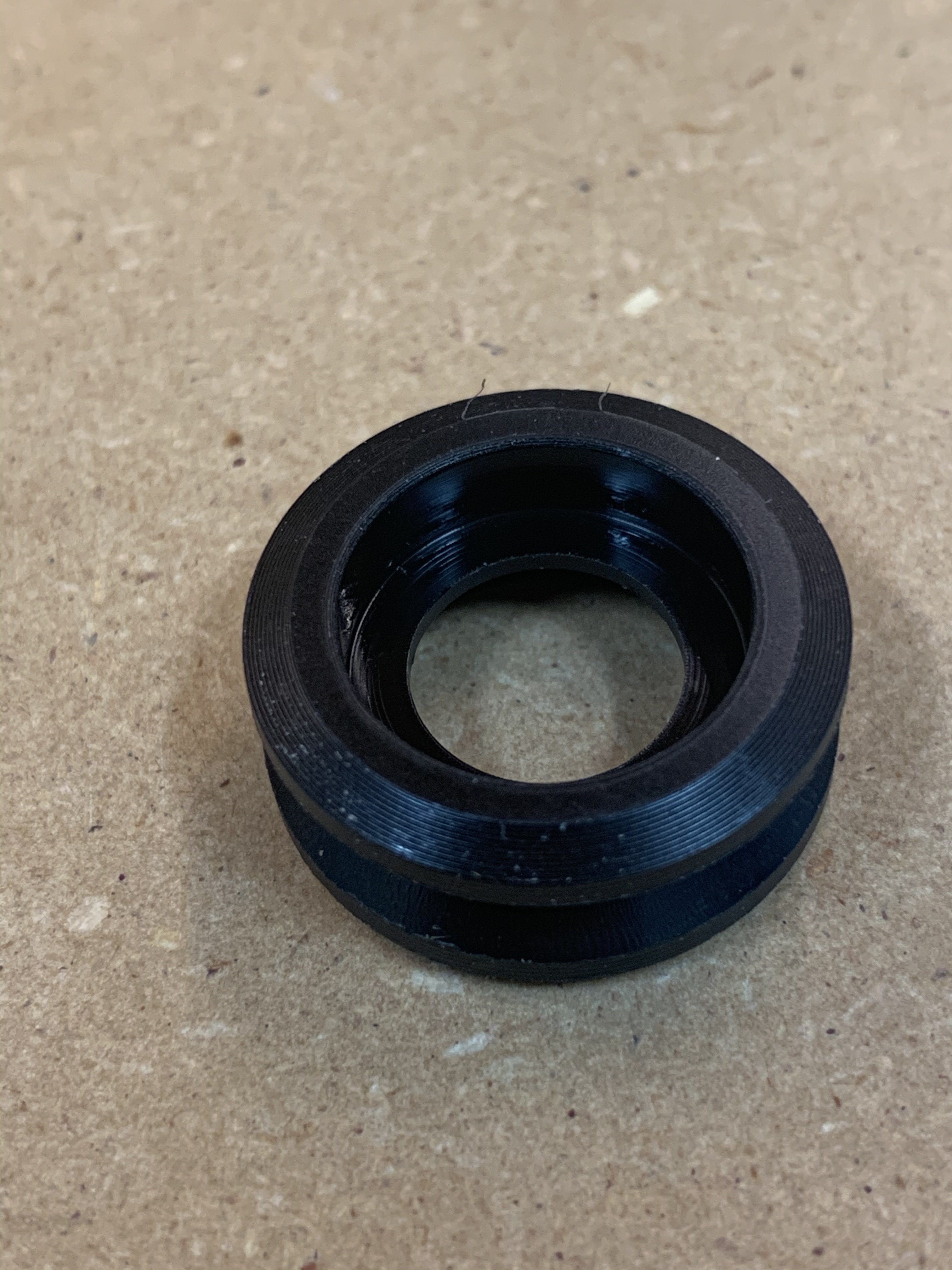
Liam, here’s a picture of the wheels that came with my machine from May of this year, and the spares in my maintenance kit. Look a touch different than yours.
I measured a few sets of shims and looks like they’re using the same stainless shims on both sides of the bearings now. On a couple sets, both measured at 0.96mm in my precision cough digital caliper.
Thanks again for the time and thought you are giving to this!
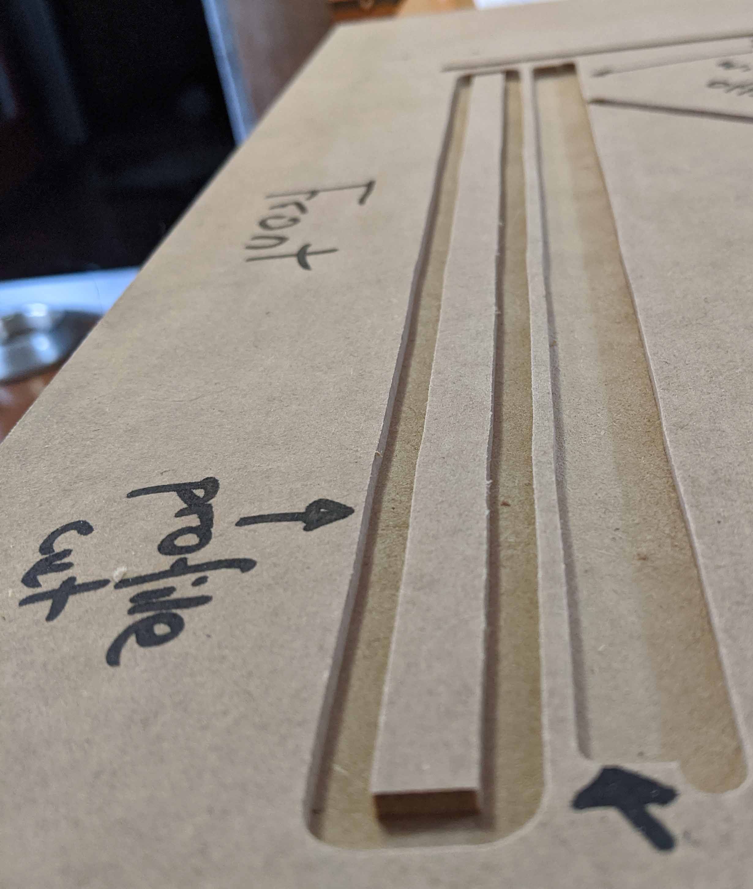
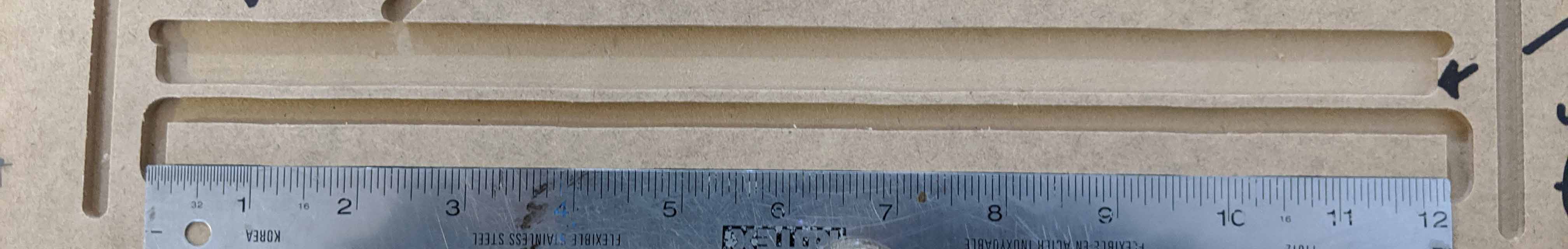
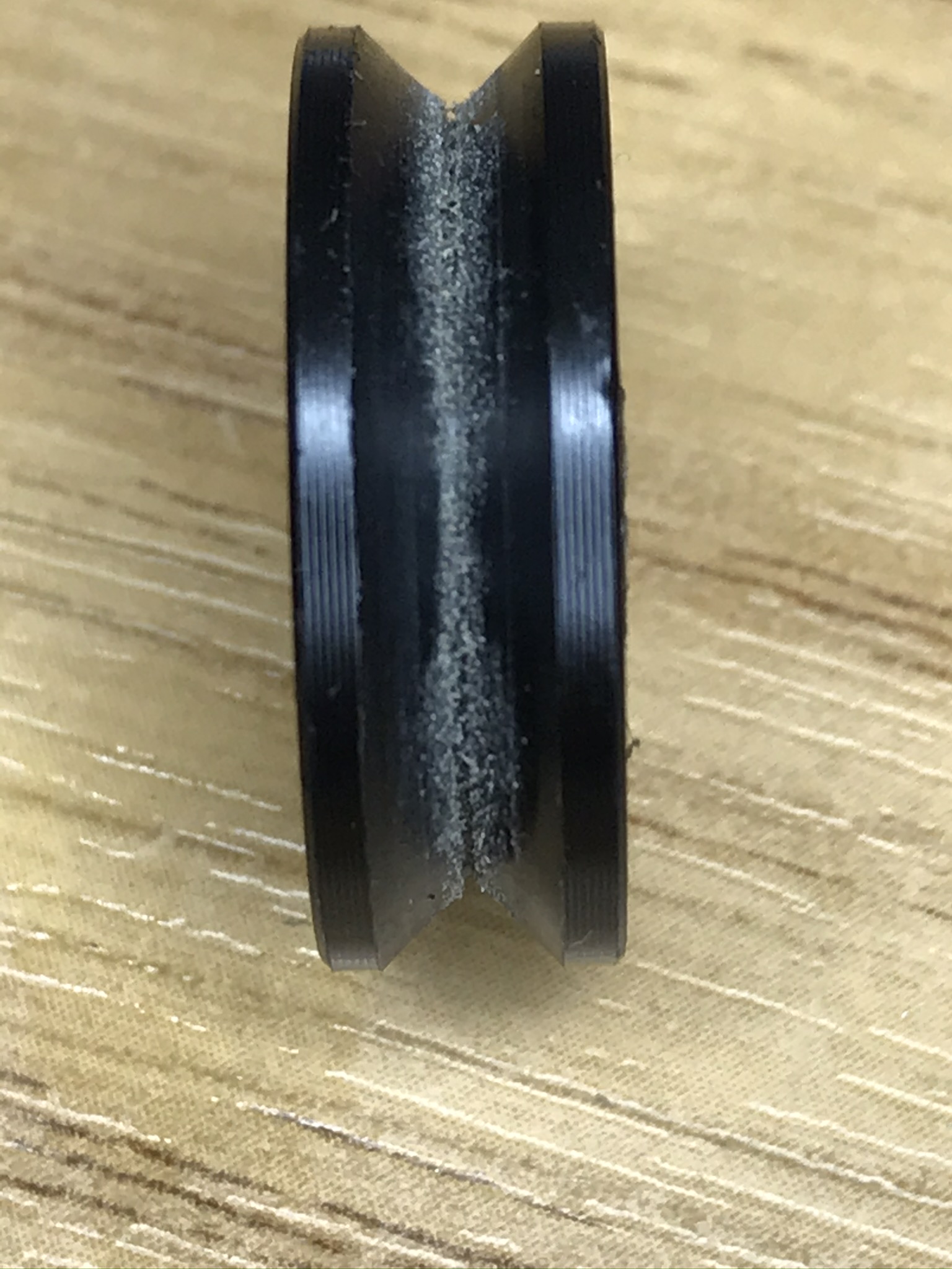
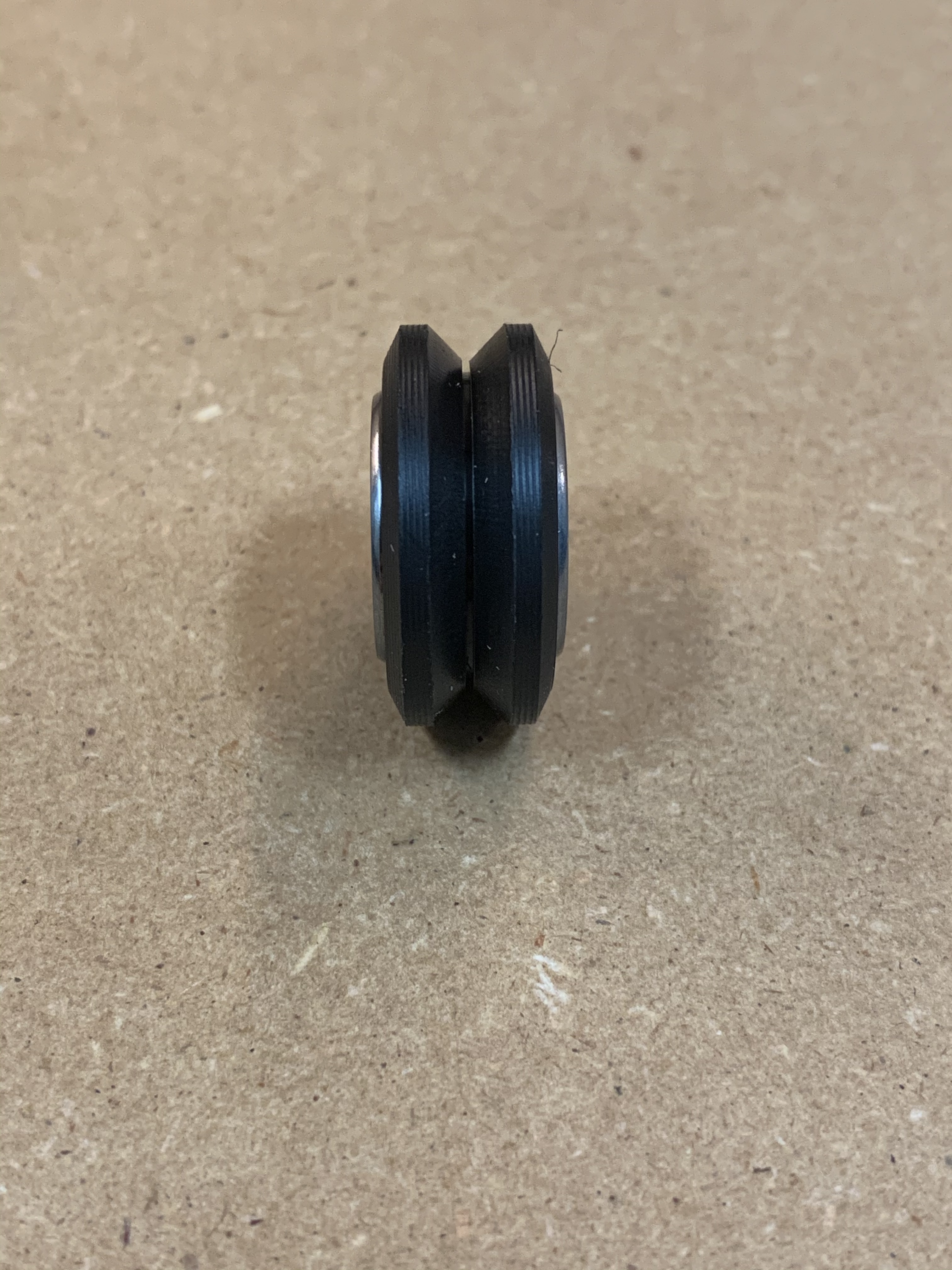
I’ve made a simple and crude jig in which a piece of wood sits in the slot of a V wheel and magnifies by about 2.5X any irregularities. Testing the bottom right wheel (the most likely offender) on this jig shows a slight eccentricity (repeating - not random) as the wheel is rotated - whether this is sufficient to account for my problem is debatable, but I suspect it is. When I get the dial guage, I should be able to confirm this one way or another.
I’ll check the other three wheels in the same way, and even if they run true, adopt Sherlock Holmes’ dictum that whenever you have eliminated all possibilities, whatever remains, no matter how unlikely, must be the truth.
Unfortuntaly it’s too late to have four new wheels sent out from Carbide 3D before the weekend, so I’ll just have to be patient and work in the garden instead for a week or two (mail is slow to Tasmania) - not half as much fun, though, but not as frustrating either.
Despite all this I remain really happy with the machine.