Hi all. New here. I’ve had my SO3 for a few weeks now and am extremely impressed with the machine.
By trade, I am an Industrial Designer but mostly, I do all kinds of lighting for cars and motorcycles. Hopefully the SO3 will make my job a little easier! I’ll be using it to make brackets for swapping factory projectors for proper, bi-xenon projectors as well as cutting out custom PCBs that I will be designing and making for different applications. For those interested, you can check out some of my previous work on Instagram - https://www.instagram.com/cappellettidesignllc/
Of course, I’ll be using it for random, fun projects too! Going to be grabbing some sort of exotic wood soon to design and cut some new legs for my glasses.
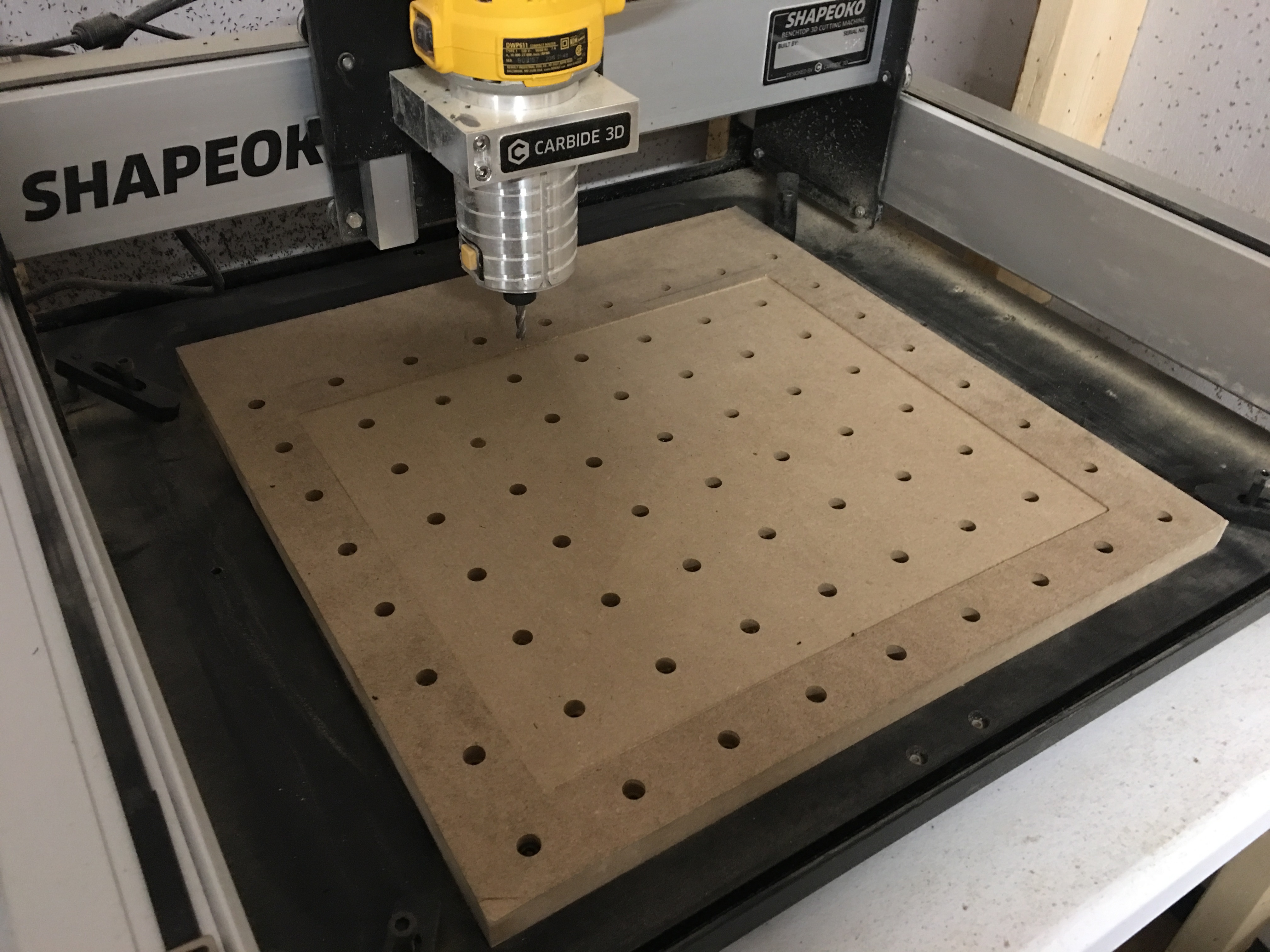
Because the majority of the stock I’ll be cutting on here will be aluminum, I went ahead an opted for the aluminum table from Carbide 3D. In an attempt to keep it looking somewhat nice, I made an MDF waste board with holes that will still allow me to utilize the threaded holes in the aluminum table and leveled it. Should be able to get plenty of use out of it before I need to cut another!
Now onto the fun stuff. I’ve CNC’d before and am familiar with the process. I frequented a ShopBot back at Purdue and loved it. Never cut aluminum though so I wanted to try a little project out before I jumped into the bigger cuts.
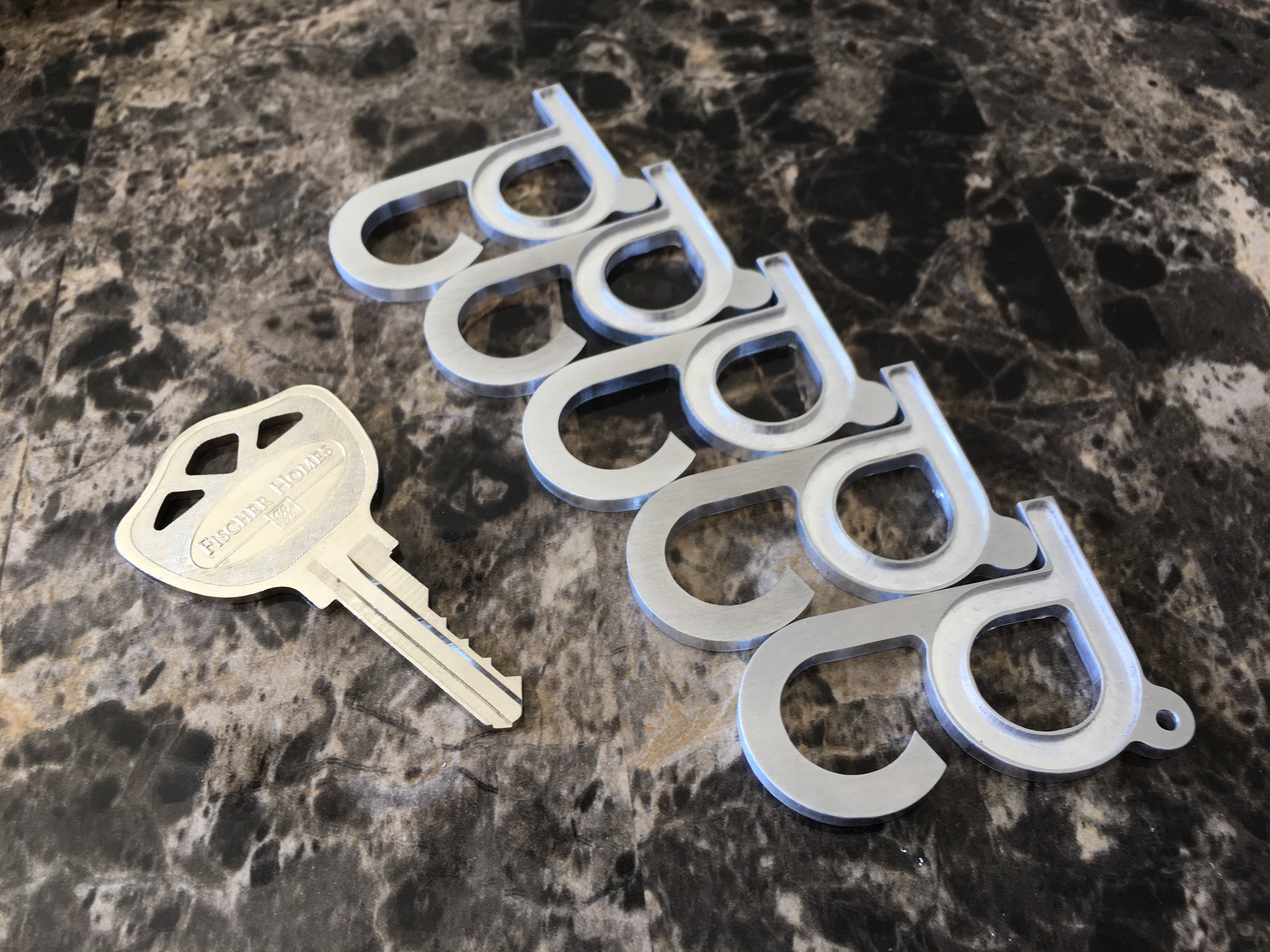
I grabbed a couple Destiny Tools 2 Flute 1/8" coated end mills, some aluminum stock from Carbide 3D, and went for it. Made a quick keychain file in Rhino (my modeling software of choice), exported as a DXF, imported into CC, and put the machine to work. The first one was okay. I adjusted my settings and the results were great! This was with manually spraying WD-40 onto the work piece.
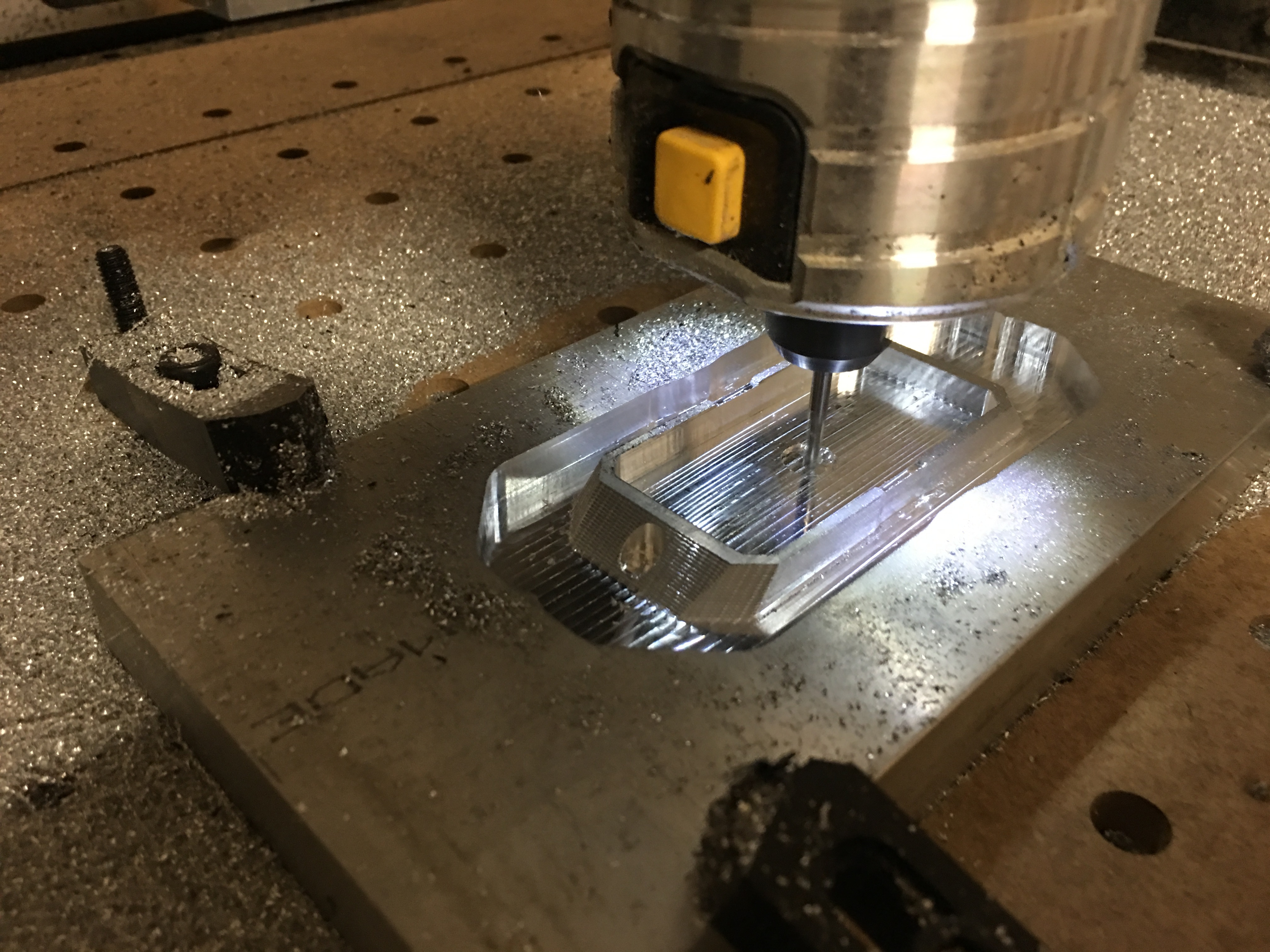
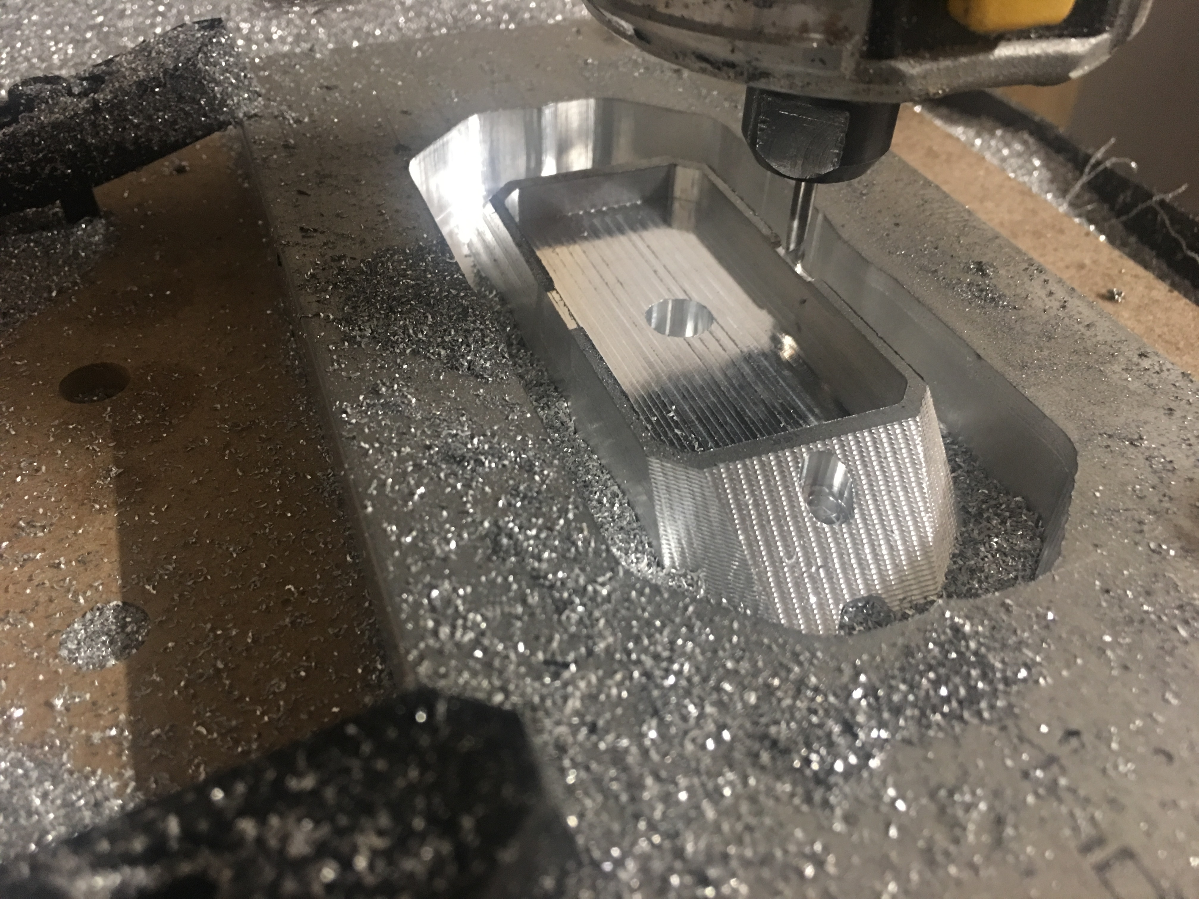
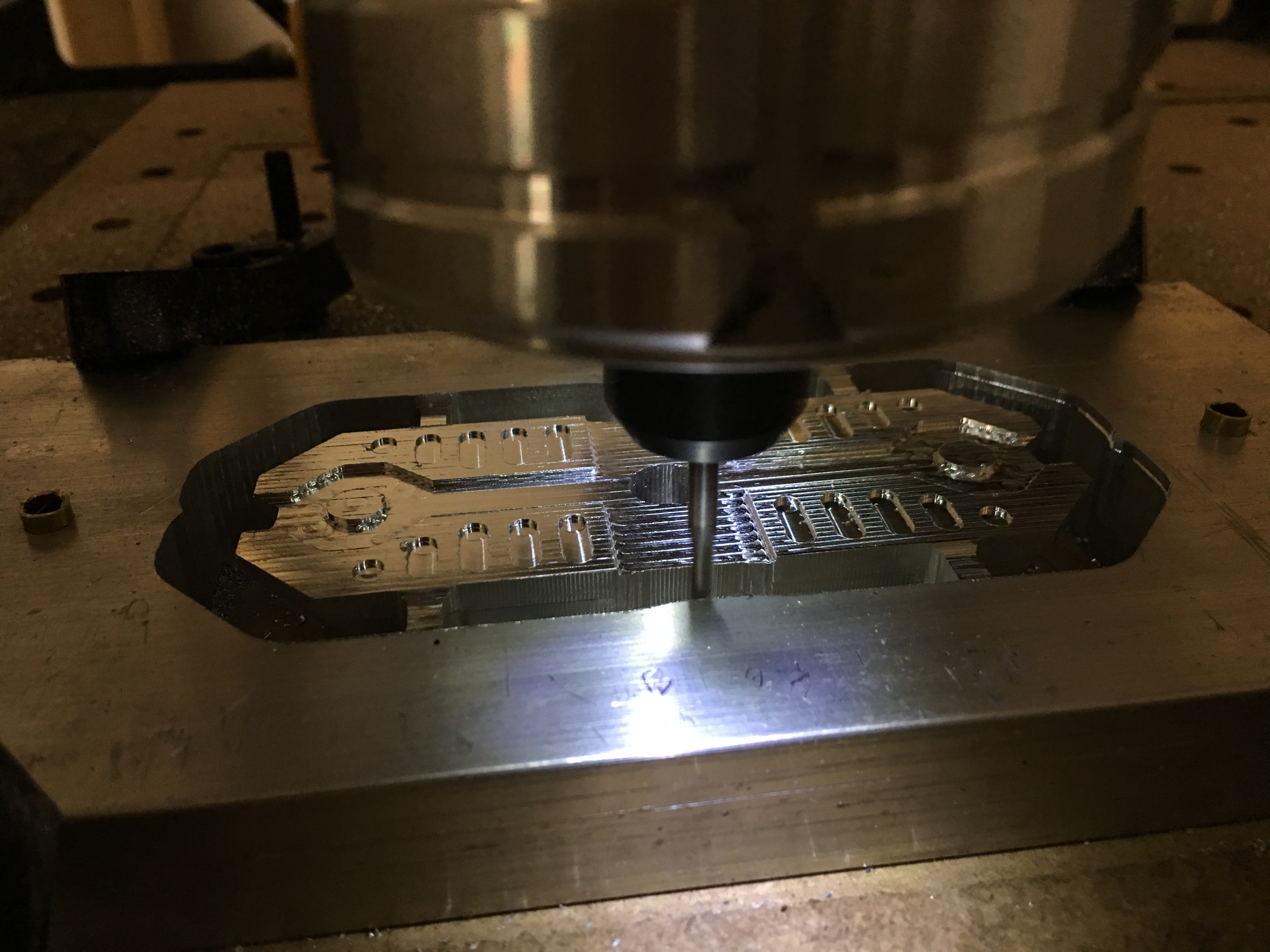
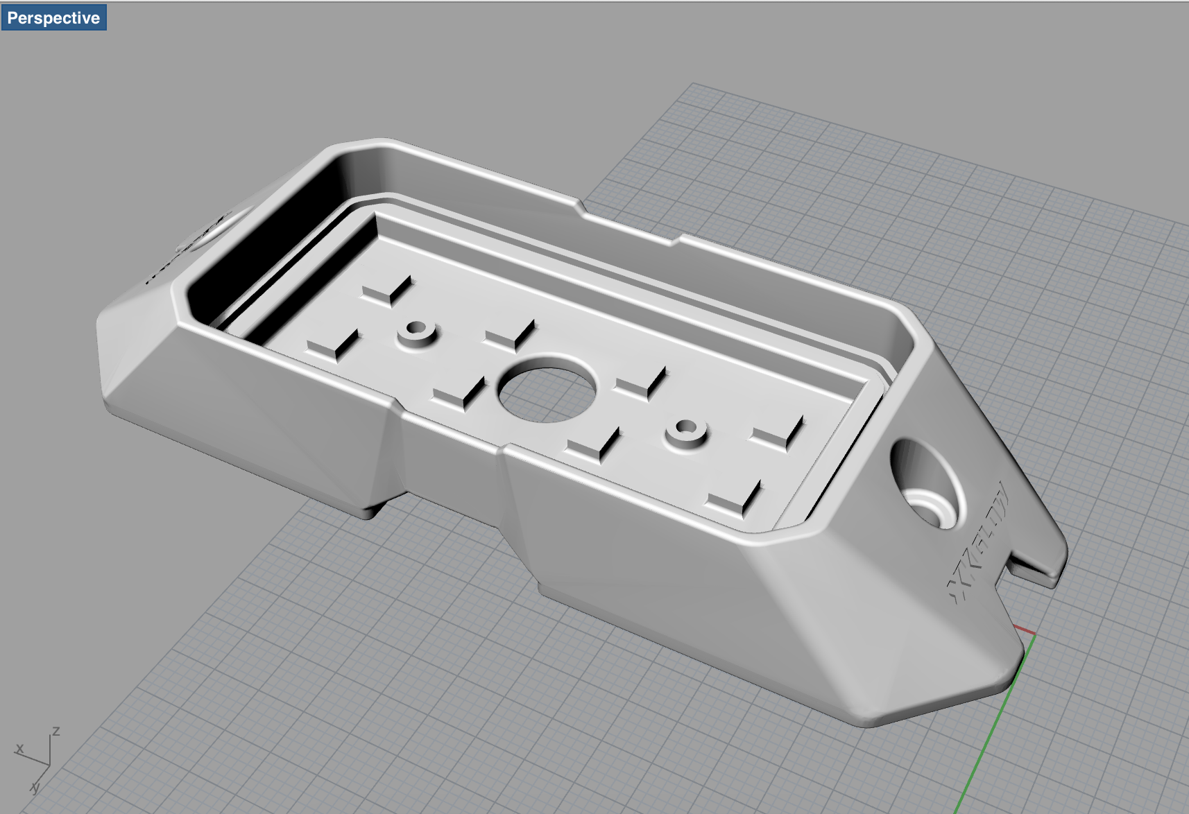
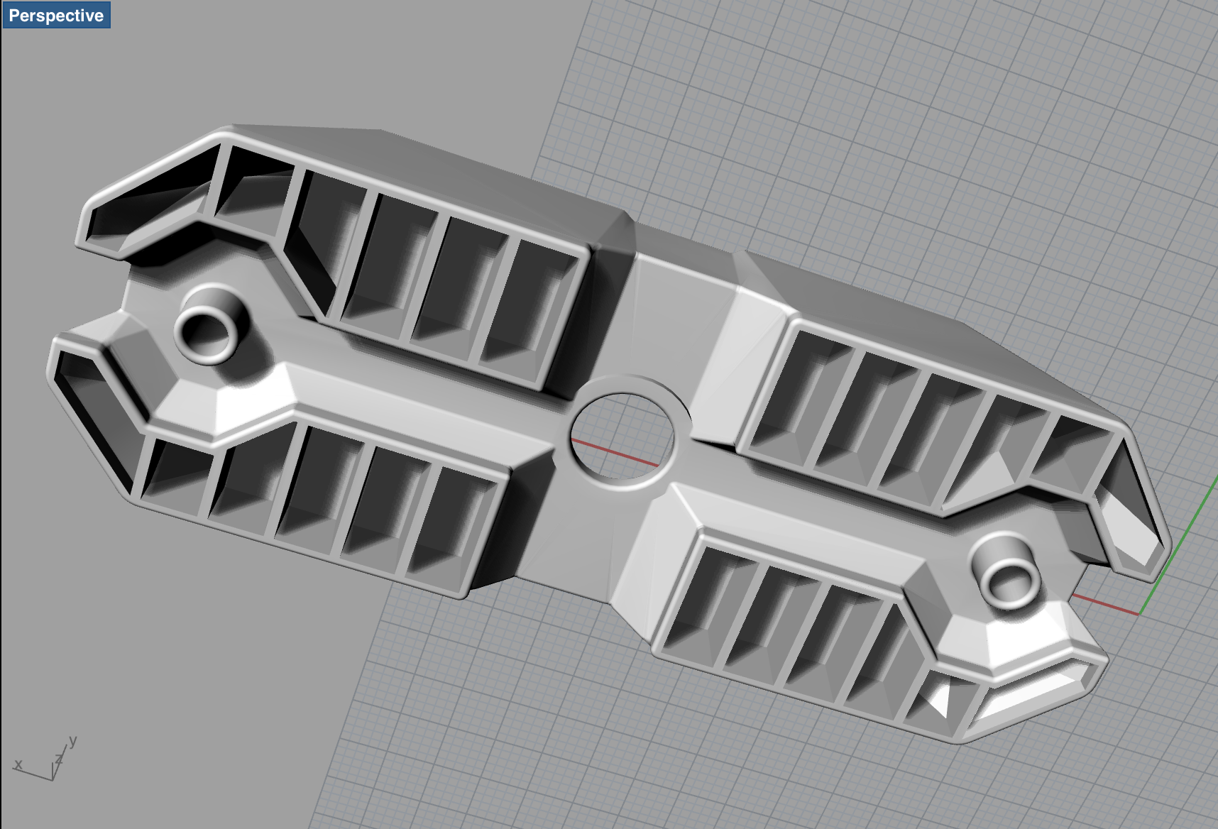
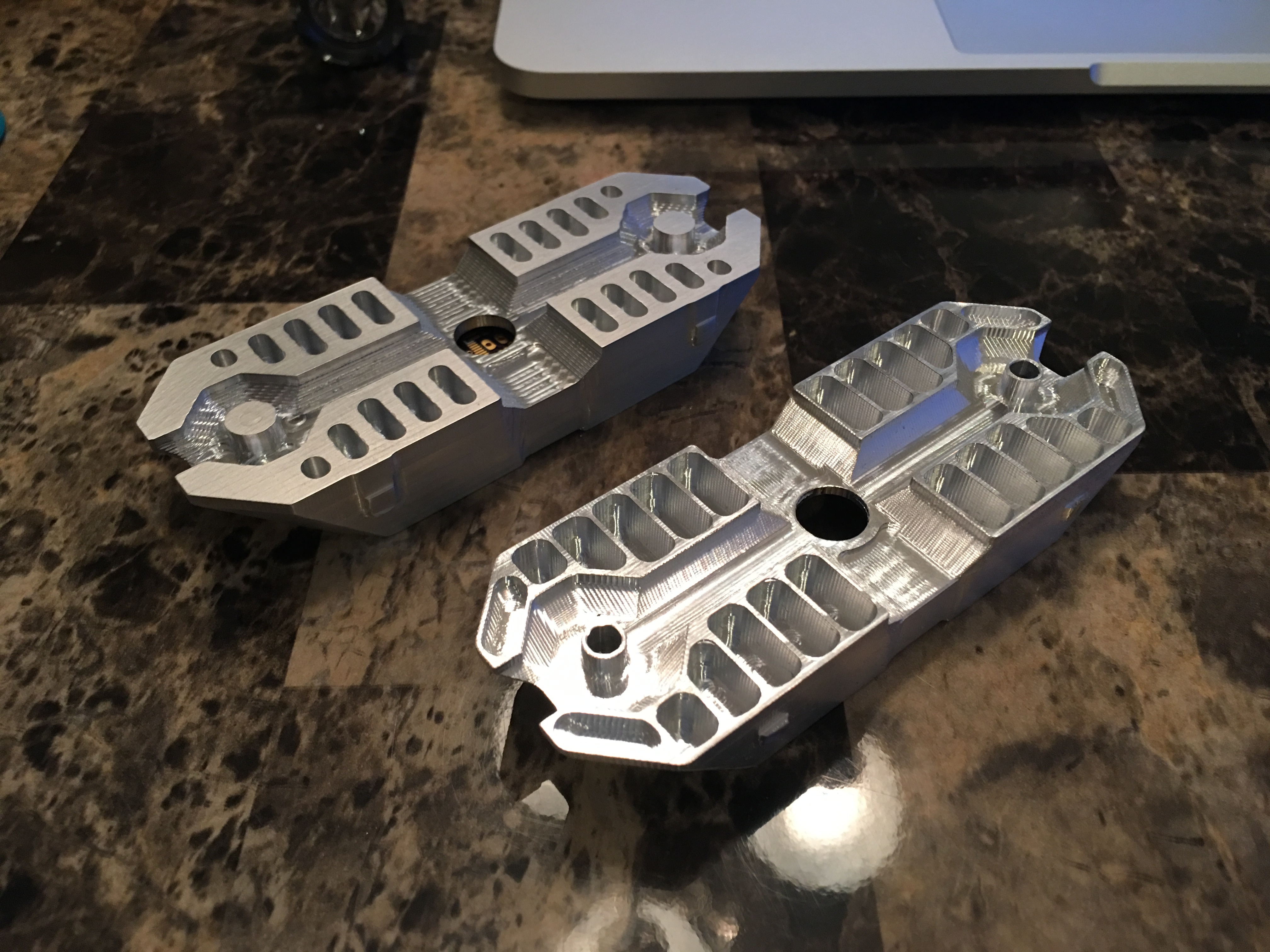
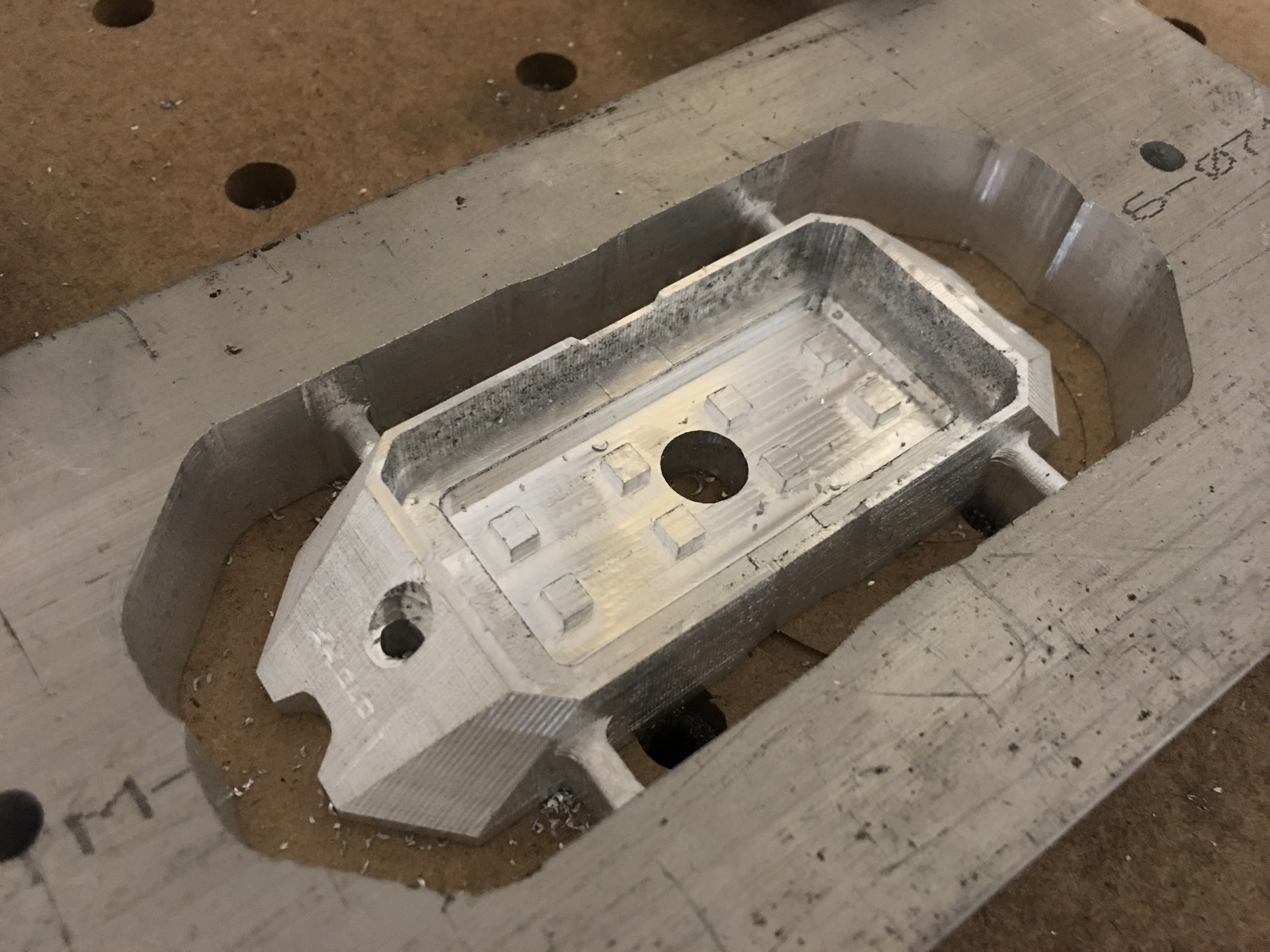
And to dig further into the aftermarket lighting realm, I am a product designer at XKGLOW. I have been working on a multipurpose pod for rock crawling/emergency strobe lighting. This one is still a work in progress. I am cutting and then changing the model in SolidWorks accordingly. Cut out of 3/4" aluminum. Was a bit intimidating at first but the SO3 handled it like a champ. Any imperfections you may see are a result of user error rather than error on the machines part! The bottom side of the latest rendition is up next.
This looks great Alek! I’ve been loving the so3 too, and am just getting into aluminium. Your part in the above photo looks amazing, I’m trying to do similar parts but am struggling a bit to get the right setup Would you mind educating me on what sort of toolpath strategies and depths of cut/ feeds you’re using? I can get good results with a 1/4 bit but can’t work out the 1/8 bit.
Keep us updated with your work, It’s looking awesome!
Hi Stuart. For the above 3/4" cut, I used the following settings with a Destiny Tools 1/8" 2 flute coated end mill- 0.015" DOC, 0.0312" stepover, 30" feedrate, and a 10" plunge rate. Worked out well for me! I could probably go a little deeper with the depth of cut but wanted to veer on the safe side. The toolpaths were generated in MeshCam.
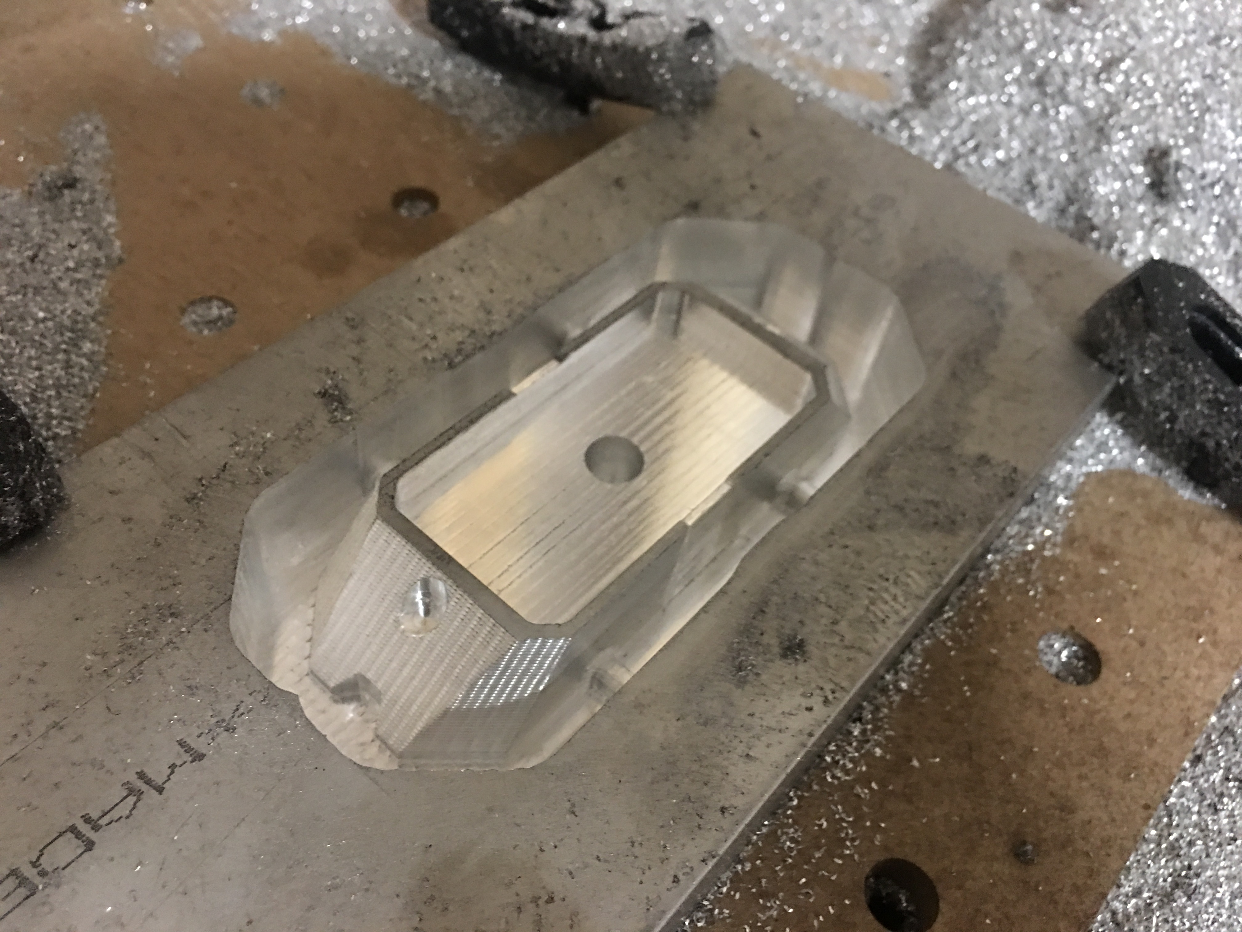
The finish could have been a little better but I used the same 1/8" end mill for the finishing pass. I need to make myself a touch plate to make post-tool change Z zeroing a lot more precise than the paper method Couldn’t get the zero right between tool changes so I just left it after the roughing pass. Touch plate is on the crazy long To-do list.
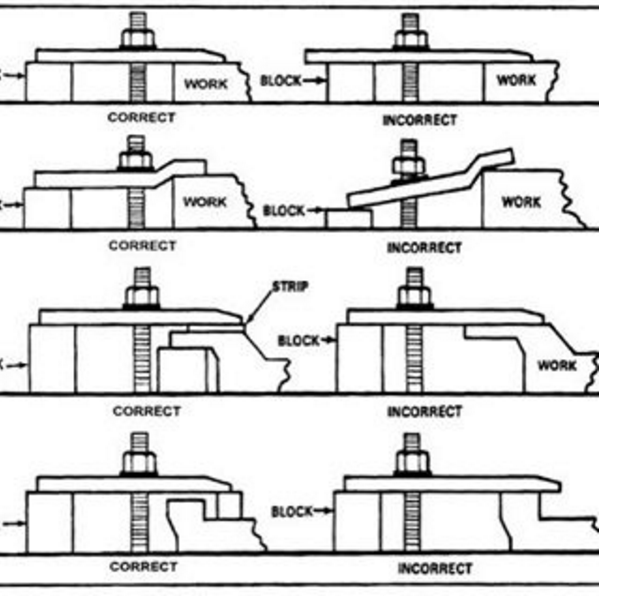
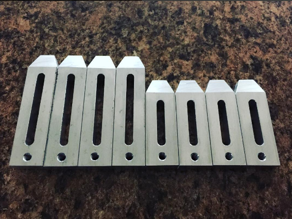
I would recommend some improvements in your clamping (See photo). I also recommend that you upgrade to metal clamps (yes I do sell them). I also recommend that you drill some holes in your work piece and just bolt it to the table and don’t use any clamps.
PS You can attach more then one photo, just tag them all at one (and wait for them to upload).
That’s roughly where I am, but I’m using ebay-spec titanium coated endmills which could be the issue… I have one 1/8 destiny viper endmill but have snapped a few of the cheaper ones so wanted to get it right before risking the viper! I’ve just ordered 5x more though.
I’ve been playing with the 2d adaptive clearing toolpaths in Fusion360 too, and getting decent results with that…after breaking a handful of endmills experimenting haha… it’s a good way to use more length of the flutes on the endmill, with a 1/8 bit I have been taking 3mm depth cuts at 1200mm/min, and a .25mm width of cut, which has much faster removal rates than the conventional pocketing, and spreads the wear on the cutting tool. The finish is poor but a finishing pass tidies it up
I hear you on the Touch Plate, I have everything I need to make one, I just haven’t gotten there yet, damn it’d save some time!! Also on the list is @RichCournoyer 's wd40 dripper can design, seems like a great way to keep the lubrication up to the job.
The latest rendition took just over 7 hours between the roughing and finishing passes. Ideal? No! But it gives me a prototype to effectively test my heat sinking design when the LED PCB goes in (production parts will be made out of 6061 just as this here).
Edit- this doesn’t include the bottom tooling time which I suspect will add a few hours
Bottom side is underway. As you can see, orientation is off by a hair in the X axis. I suspect this was due to me switching my zero location from the lower left to the center between cuts. Live and learn. Will be fixed next time!
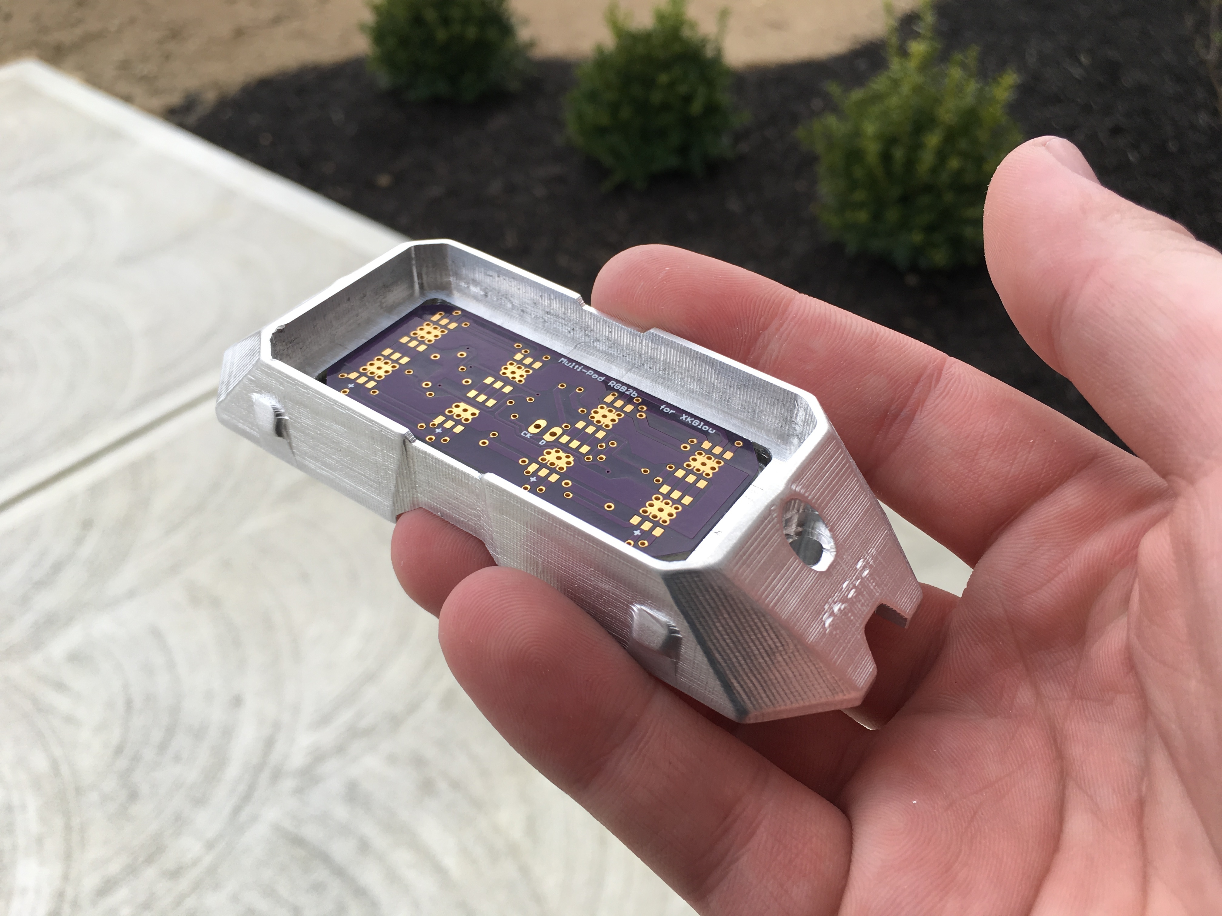
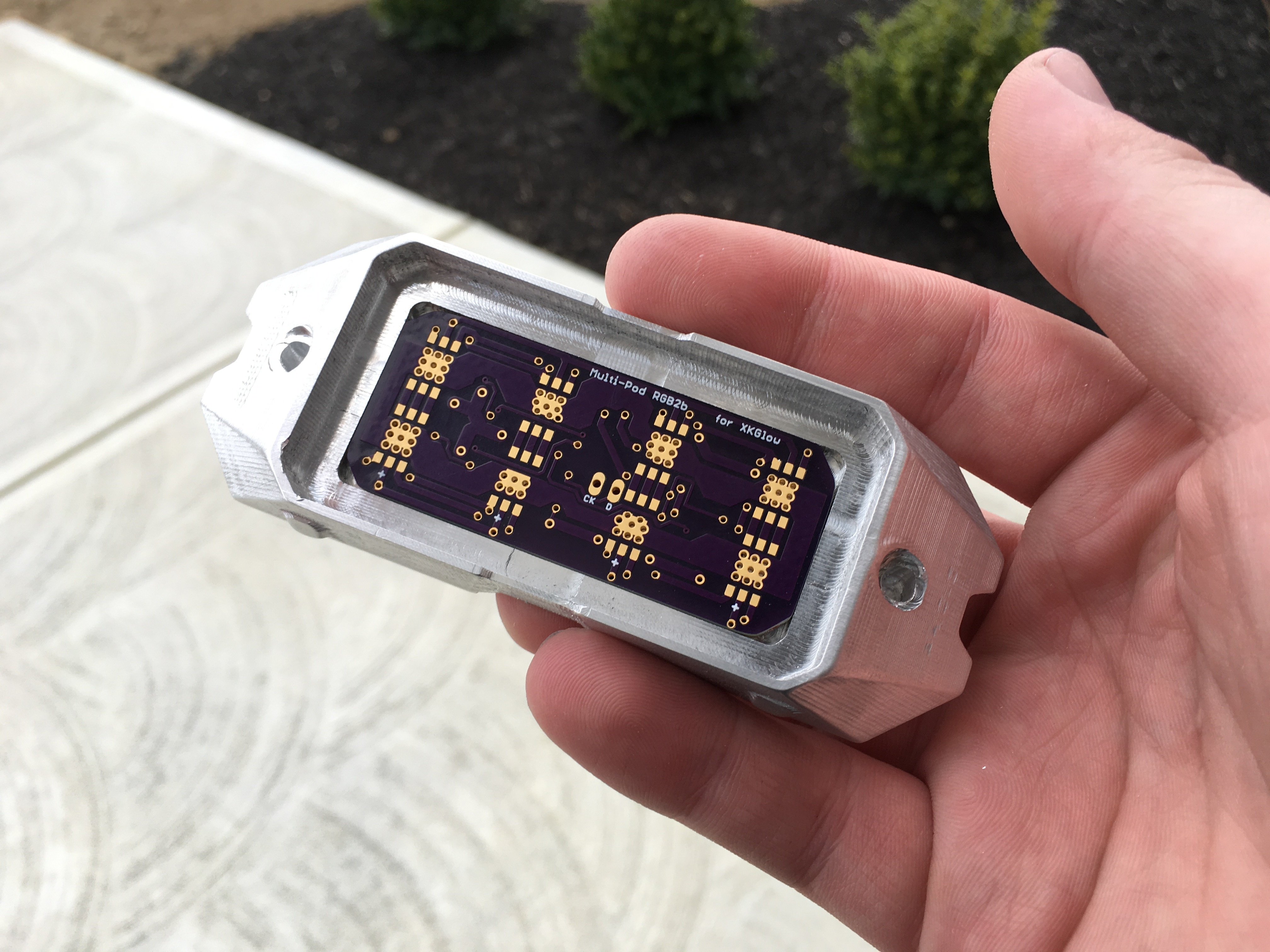
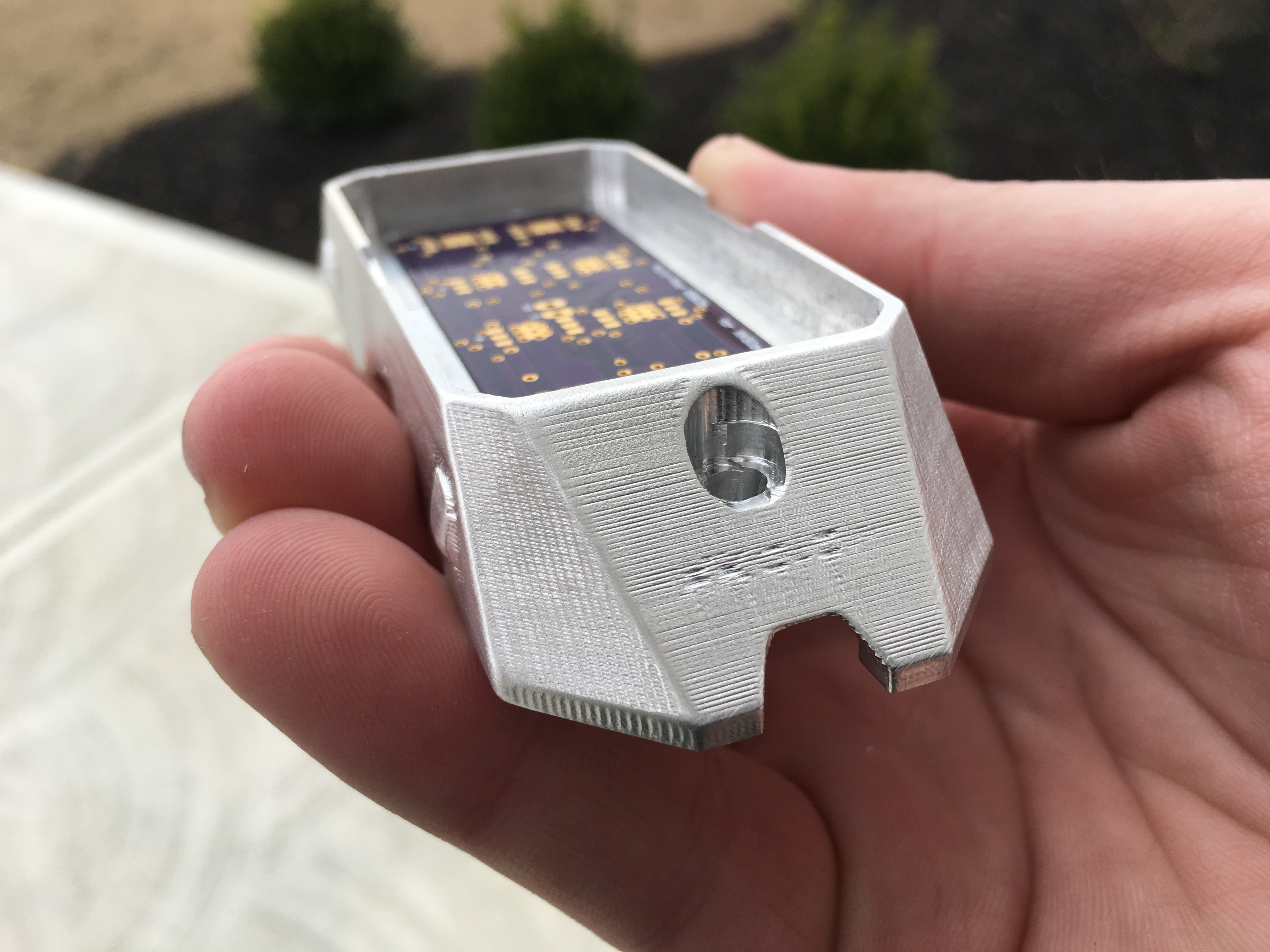
Offset wasn’t too bad as it wouldn’t have removed material until the finishing pass with .01" left to remove. Stopped it before it got to that point. Overall pretty happy with this cut. I need to get myself some coated 1/16" end mills! Detail could be much better. Here’s the housing with the PCB.
For those interested, I thought I’d share my workflow and the reasoning behind it.
I will be using Carbide Create for the 2D cuts and MeshCam for the 3D. Zero will be set to the center of the stock which is 3/4" 6061 aluminum. 4" high and 8" wide.
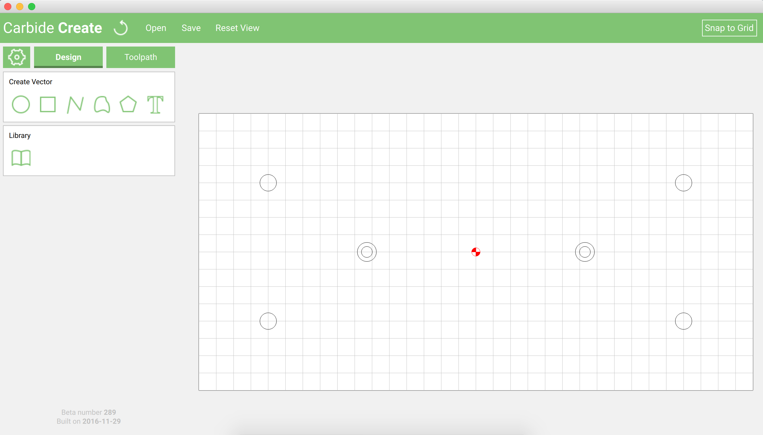
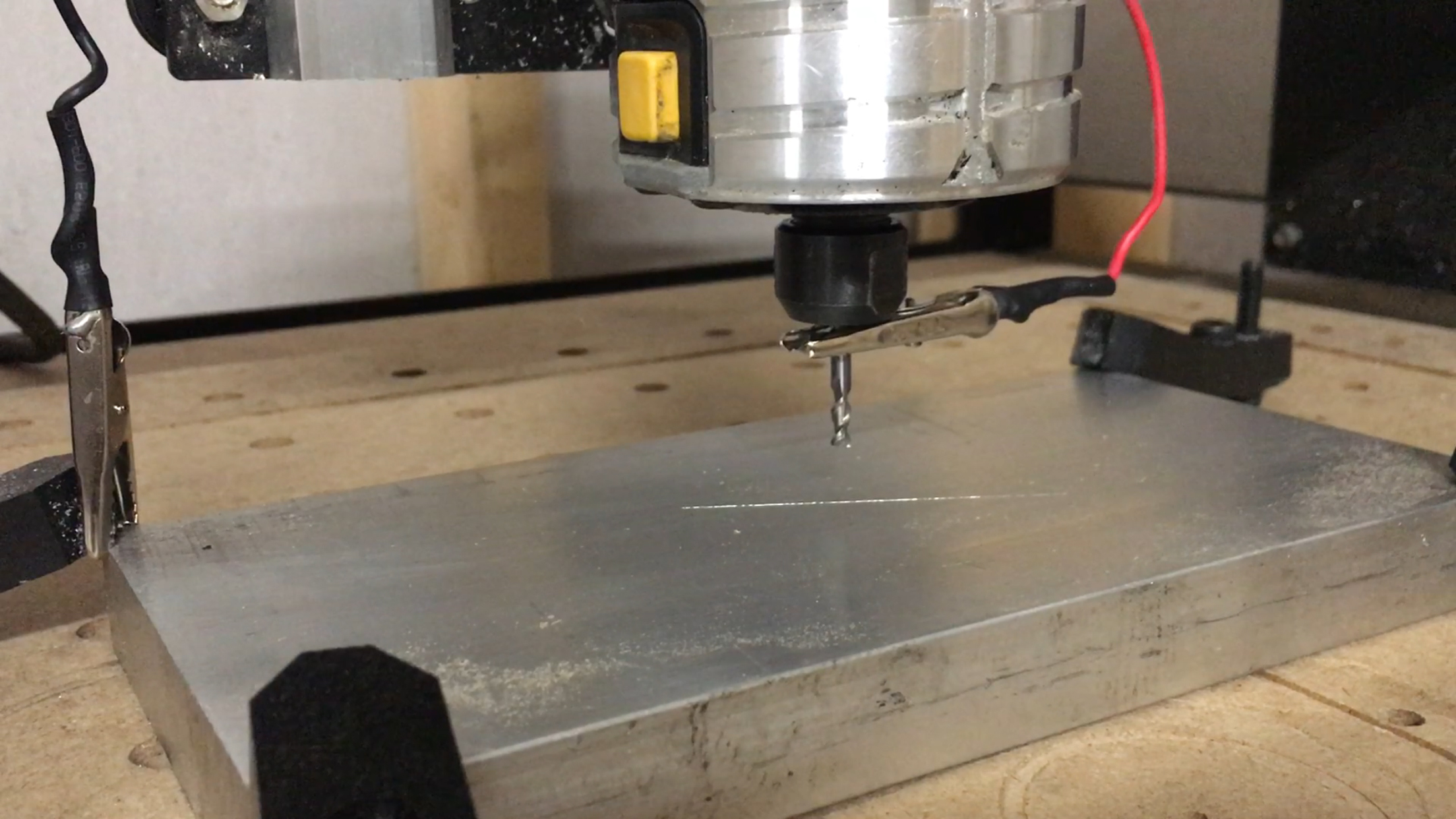
For starters, I’ll be drilling 4 holes into my stock for dowels when I go to flip the stock to machine the bottom as well as the mounting screw holes in the pod assembly. From previous cuts, I learned that the roughing pass generated in MeshCam does not remove enough material here so when the finishing pass gets to that point, it causes the Z-axis to skip and lose it’s spot. Cutting it prior with Carbide Create is the fix that I’ve come up with. We’ll see if it works! My initial cuts are below-
Next, I’ll run the roughing pass and finishing pass generated in MeshCam. I’ll be using the same 1/8" 2 flute coated end mill from Destiny Tools for all cuts (I have a ball end mill but need to make myself a touch plate before I swap tools mid cut. It’s coming!).
Fast forward ~8 hours and I’ll be removing the stock, setting the Z-zero to my MDF washboard and drilling the same 4 holes that are in my aluminum stock.
The aluminum stock will then be flipped and oriented with the 4 1/4" dowels, clamped down, and the bottom will be machined. Roughing pass followed by the finishing pass again, with the same 1/8" coated end mill.
If all of the above goes well, this should be my final prototype of the design before we get to testing the effectiveness of the heat sink. The PCB will be sporting 8 1.5W RGB LEDs. The housing should do just fine but it’s nice to be able to get real world test results. Before the SO3, this wasn’t possible without outsourcing for the housing! Now, it’s just done in my garage
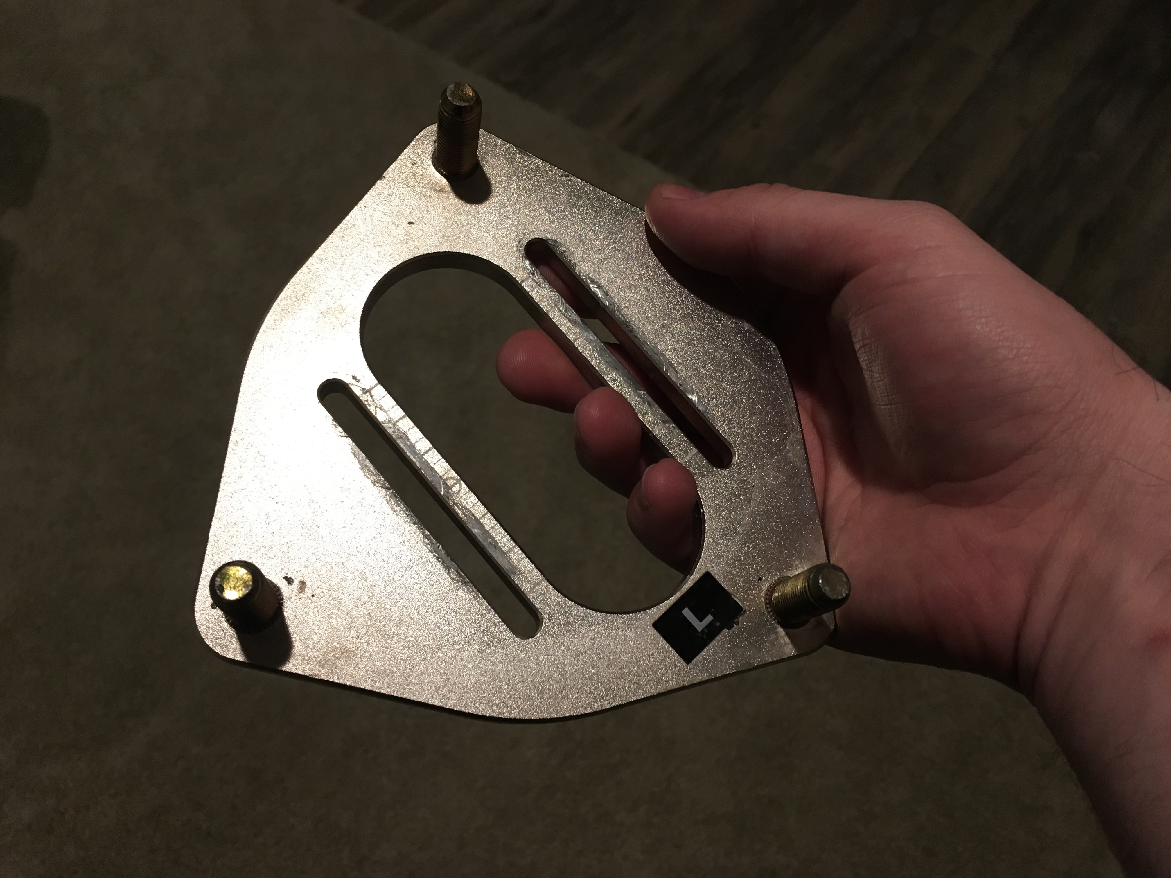
Also, another quick-ish project I’ll be knocking out this weekend for a buddy-
This is one of the top-hats off of his coilovers for his Hyundai Veloster. The notches allow for easy camber adjustment in the front. Simply loosen up the bolts on each side and slide the top of the strut over. Wheel tilts in/out accordingly. Well…he want more adjustability so I’ll be adding in some material where needed and extending all 3 notches. Will be cut out of 1/4" 6061. Should be easy relative to the complex 3D stuff above!
Currently running the finishing pass on the top side of the latest pod. Got the roughing pass down to 4.5hrs.
I just got an 1/8" coated ball end mill to use on the finishing pass. Unfortunately, it broke 2 minutes in on the 78 minute pass.
I have been using the same 1/8" square end mill in all of the cuts above without hiccup. My takeaways? 0.01" of material left to remove for the finishing pass was too much for the ball end mill. I have the finishing pass running with the square end mill and it’s almost halfway through. Next time around, I’ll leave only 0.005" or less to remove.
Each cut is an opportunity to learn and every cut after is an opportunity to improve. As noted above, my Z belt would skip on the finishing pass when it would hit the mounting holes no matter what I tried. Well…drilling out the holes first worked out perfectly! Finishing pass went through that section no problem.
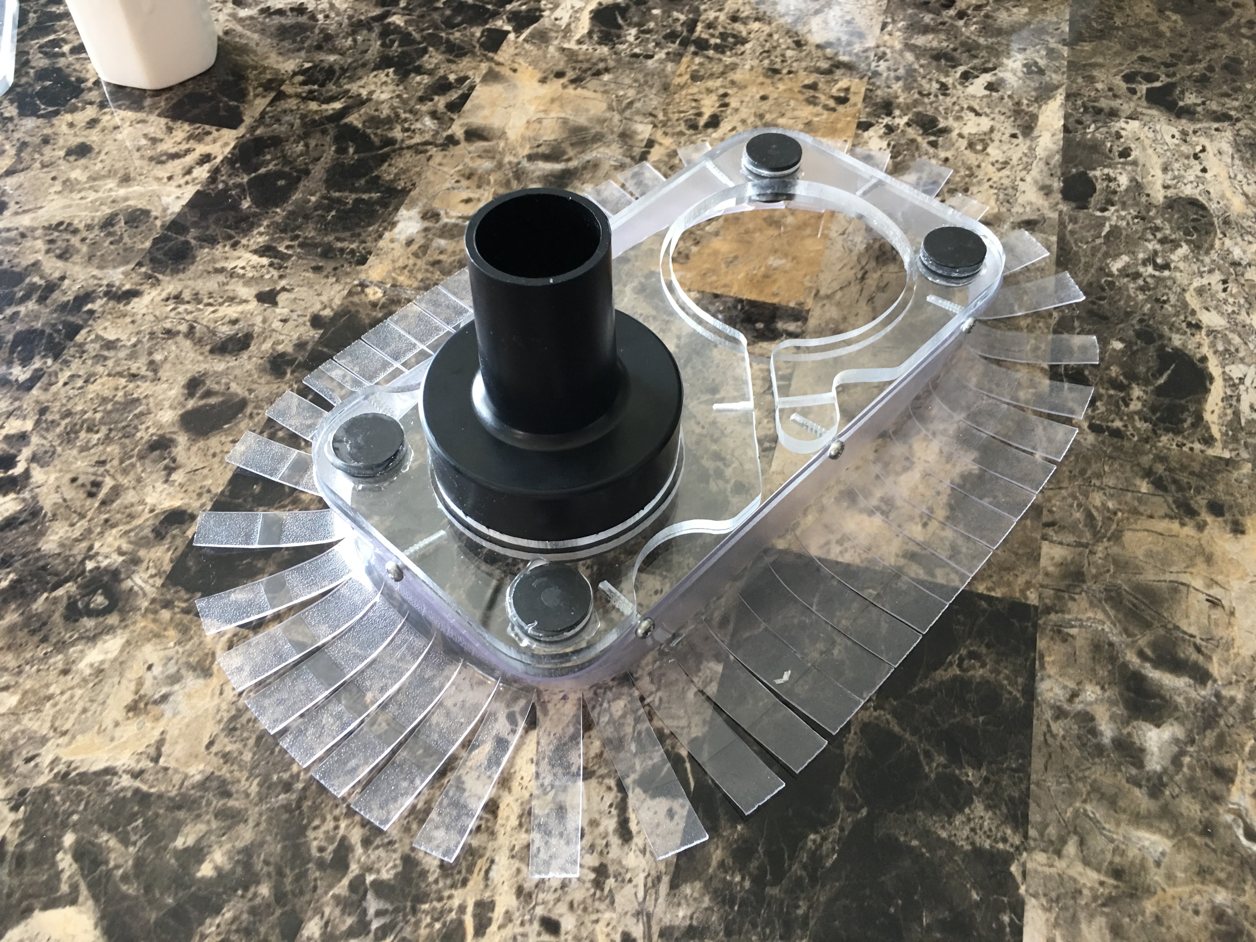
Also went ahead and made a dust shoe before I get the new garage too messy (brand new house!). Clear so I can still see my cuts and magnetic for easy removal during tool changes.
 Couldn’t get the zero right between tool changes so I just left it after the roughing pass. Touch plate is on the crazy long To-do list.