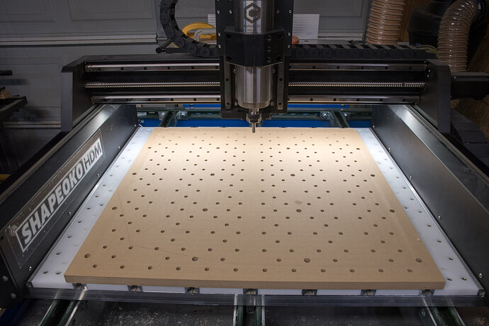
I’ve spent a few months with my new slats and spoilboard and if I had it to do over again I wouldn’t change much, if anything. I think this setup lends itself well to systems like the HDM or any other machine where you want to do both wood and metal, but the ideas it incorporates lends itself to other machines and may give some of you some ideas you may wish to incorporate into your own system. It takes a bit of time to set up, but once you get it going the various elements will last much longer than a conventional spoilboard for reasons I’ll cover.
My HDM started with the standard hybrid table. I replaced all of the original 3/4" MDF slats with 1/2" HDPE. The HDPE supplier in the link cut the HDPE to the exact specifications of the original ones. Since I always use either an mounting plate or MDF spoilboard on top of the hybrid table, there was no need to go with 3/4" thickness for the slats. The HDPE allows me to use liquid cooling without having to remove the MDF slats. If you have no need for liquid cooling, MDF is going to be a cheaper option for the slats.
The slats each have a grid of three columns of 8mm holes(actually 8.05mm to allow clearance for the 8mm stainless dowels). The two outside columns have the holes spaced 50mm apart both horizontally and vertically. There’s also 50mm of spacing to the next set of outside columns for the next slat. All of these holes get a 6mm x 10mm threaded insert installed from underneath. In between the two outside column is one inside column offset by 25mm. These holes do not get threaded inserts. You wind up with a set of 5 holes which repeat along the length of the slat. When installing the slats I use a 8mm collet and 8mm stainless dowel along with the spindle to perfectly align the slats with 50mm spacing horizontally since there’s just a bit of lateral play.
Naturally if you have a differently sized system your spoilboard may be a different size. My MDF spoilboard is 650x650mm with a grid of 25 countersunk holes which are used to mount it to the T-track. I found out the hard way you don’t want to overtighten any of these screws as it will deform your MDF, so better to use more of them and tighten until just snug. After the network of mounting holes were made I installed a 1/4" piece of plywood with the same network of mounting holes between the MDF and hybrid table so I would not cut into my slats for the next operation. The MDF is aligned to the front of the hybrid table.
Next I cut a 8.05mm hole that aligns with the first hole in the 2nd row of slats. Into this hole goes a 8x45mm stainless dowel all the way through to the matching hole in the slat. Next I will cut another hole 550mm to the right of the first and install another dowel for alignment and do the same thing for the rear corners at the extent of my Y to the farthest matching hole in 50mm increments. Once each corner has a dowel installed I can go to down and cut the entire grid of matching holes with my slats. Once I had all of those holes done I moved my entire spoilboard forward, realigned everything with the 8mm dowels in the corners, and drilled the remaining holes that were beyond the extent of my Y axis.
After all the holes were cut I removed the 1/4" spacer and reinstalled the spoilboard using the alignment dowels and surfaced the entire spoilboard as you normally would.
Now my entire spoilboard has 8mm feedthrough holes which I can use to access the threaded inserts or install dowels to align my workpiece. I use a few sets of quickset macros to set my zero point for my most used rows and columns of dowels. I can use the Shapeoko Essential Clamps with the threaded inserts and 6mm x 40mm screws to hold down most workpieces. I much prefer using dowels for alignment rather than the screwed down L brackets more commonly used. The stainless 8mm dowels are more precise, but wooden ones can be used if you want to leave them in and don’t want to worry about cutting through them.
The beauty of this system is when you have used up your spoilboard, you can simply make a new one without losing all your threaded inserts.
