In theory, it’s simple. I just draw the identical shape, then cut on 2 different pieces of wood and glue the cut shape from wood piece 2 onto the cutout from wood piece 1. Turns out, it doesn’t work that easy due to, what I suspect is the cutter width.
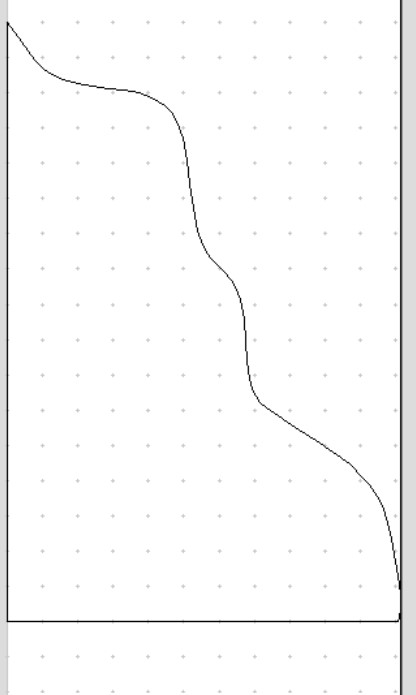
Does anyone have any ideas? I attached a very simple picture of the design for reference.
If I understand you correctly, the issue will be that the tool takes up material from one side of the line (or both if you are profiling ‘on’ the line).
So… the first cut will need to cut on one side of the line, and the second cut on the second bit of stock will need to be other the other side of the line.
In CC this is inside/outside, but you can arrange the toolpaths in several ways to achieve this result.
You should be able to just cut on the outside. That will ensure you are cutting the shape as drawn.
If you’re trying to do an inlay, the situation is different.
Maybe share your actual files?
I tried to upscale the part to be .25" bigger. Meaning, since I originally cut out the little traingle part on the ‘outside’ tool path, that meant the actual cut went .25" more into the base piece of wood. So, I cut a piece of MDF as a trial to be .25" bigger…nope…it is too big. I’m sure the answer to this is suuper easy once I understand it.
The file (as someone mentioned) is just that shape in the image above with a profile cutout tool path. Nothing fancy. The goal was to cut out the image below and then cut exact replica’s to glue in place, but with another style of wood.
Here is an idea of what I am trying to do. This particular board was done free hand with a rickety band saw and while I think it looks cool, I wanted the joint to be tighter. So, I assumed this would be a cool/easy job for the CNC…apparently not (at least not for me yet).
Any ideas?
So you want to remove the cut portion and replace with the same thing from a different stock?
Then do as @Gerry said. The “hole” should be cut inside the profile and the replacement should be cut outside the profile.
This will only work if there are no internal areas that your bit can’t cut.
The inside/outside should work, IF you don’t have any places where the curvature is tighter than the radius of your end mill. In that case you can modify the curve by doing an offset in one direction by at least the radius of the end mill; offset that in the other direction by twice the original amount; offset that in the original direction by the original amount. You now have almost the same shape, but any tight curves have been relaxed to accommodate the size of the end mill and things should fit.
David specs a classic procedure to fix curves with tight spots. Put this in your notebook for now and later.
PS. I’ve only highlighted the fact that this is a process to fix a curve so you don’t have to rebuild the whole curve. Many times these gems just roll off the screen.
Please note that this technique works in Carbide Create because the default behaviour when offsetting is to round off by the radius of the offset — in most drawing programs one has to specifically change the offsetting procedure settings so as to cause that.
Thank you all for the comments. I went with the inny/outty process and it seems like a winner. I also moved to a 1/8 bit to allow for curves to be smoother. The piece is in clamps now with glue and I hope to share pics later. Thanks again!