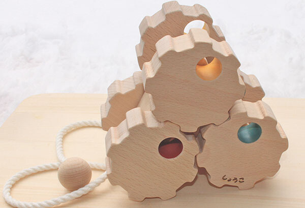
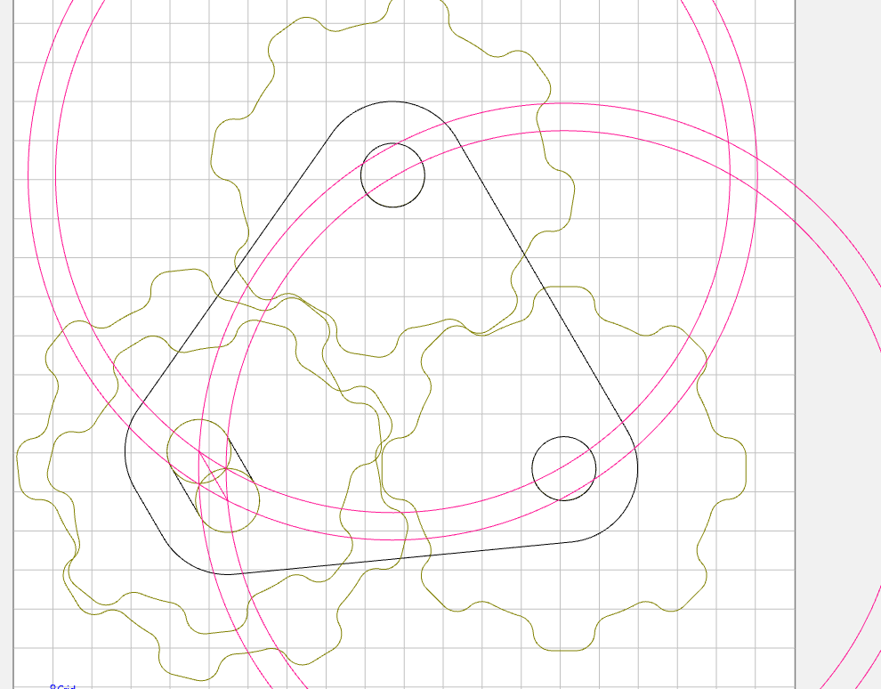
I’m trying to recreate a wooden pull toy similar to the one shown in the reference photo. The wheels have an 8-lobed “gear-like” profile and are intended to rotate together as the toy is pulled.
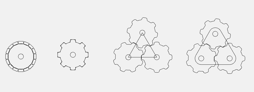
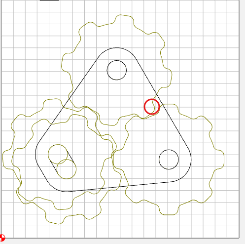
I designed the wheels in Carbide Create and machined them on my CNC. The individual wheels came out well, but when I assemble them, they don’t rotate together. Instead, the lobes bind against each other and the wheels get stuck.
I’m wondering if I’m missing a basic design principle.
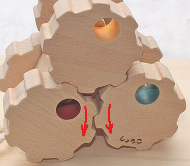
The image on that page seems to show that the bottom two wheels do not mesh (as was pointed out before) which will then allow things to rotate as expected.
I tried increasing the center-to-center distance, but there’s a catch. This toy is designed so that whichever two wheels are touching the ground should drive all six wheels.
If I increase the spacing between the bottom pair, that particular orientation works and all six wheels rotate. However, when the toy is tilted onto one of its other two sides, the new bottom pair no longer meshes correctly, and the wheels bind. The same issue simply shifts to the other pair of wheels.
Because the toy is meant to work in all three orientations, increasing the spacing alone doesn’t solve the problem. It makes me think the original design uses a different wheel profile or some other geometric relationship that I’m missing.
There is a fundamental gearing geometry problem. You cannot have a trio of meshing gears that turn. With the “red” and “blue” gears in mesh they are constrained to rotate in opposite directions
which will bind the “yellow” gear. The only way for this to work is to space the “red” and “blue” gears a little farther so they do not mesh. I think that you are right in that they just designed a lot of slop into the wheel axles. In fact, in the video on the Japanese webpage, you can see one point where the wheels are locked up right before the user “unfolds” the mechanism again…
I was thinking about the slotted axle that Tod with 1 d posted as one of the approaches.
I looked at their non geared version just do do some calculations
The top of the list showed a width of 160 mm
and a height of 145 mm
with the pull string on one face of the the triangle block
Do putting together a spreadsheet to calculate the position of the axles based on the dimensions given. (some simple Pythagorean theory a^2 +b^2= c^2
To get the dimensions given
I assumed a gap between the two lower wheels, of a certain dimension
From the width of the toy the I calculated the radius of the wheels by (width-gap)/4
from that I calculated the position of the axles
the lower axles are separated by 2 x radius plus the gap
the upper axle position is centered in x, the height involves ol’ Pythagoras
the upper axle is 2 x radius away from the other axles. You can make a right triangle to give the height above the other axles with hypotenuse 2 x radius, and length along x= radius+ gap/2
so the height in y above the other axles is sqrt( (2radius)^2- (radius+gap/2)^2)
I then adjusted the gap in the spreadsheet to get the specified height
(I tried attaching the spreadsheet but not supported for xlsx or zip) The text cut and paste is a little scrambled. But you get the idea.
|input|width |160|mm|
|input|wheel gap|3.5|mm|
||height|145|mm|
||radius|39.125|mm|
||axle separation|81.75|mm|
|||||
||(2)r^2|6123.1|mm|
||((r+gap/2))^2 |1670.8|mm|
||height above axle|66.7|mm|
|||||
||calculated total height|145.0|mm|
|||||
||top axle x|80|mm|
||top axle y|105.9|mm|
|||||
|lower axles|Lower axle x (#1)|39.125|mm|
||Lower axle x (#2)|120.875|mm|
||lower axles y (both)|39.125|mm|
edit- thought about this a little more the gap always has to be on the bottom. But this will help calculate the positions to get the gap to work
You have hit on the core requirement, John. The two wheels in contact with the floor cannot be meshed, no matter which two they are. But we want the “upper” wheel to be in mesh with the other two (or at least one of them to be driven). In the Japanese video(specifically the g007), this is not a triangular fidget, but it can be unfolded to be linear with all three wheels on the ground. In that case, none of the wheels can be meshed. I stick by my theory that it depends on a lot of slop in the axle fits and the frame pivoting, and even then is not guaranteed to not lock up. The g003 variety is triangular but they keep in in a single orientation (with the properly spaced lower wheels) for the whole video.