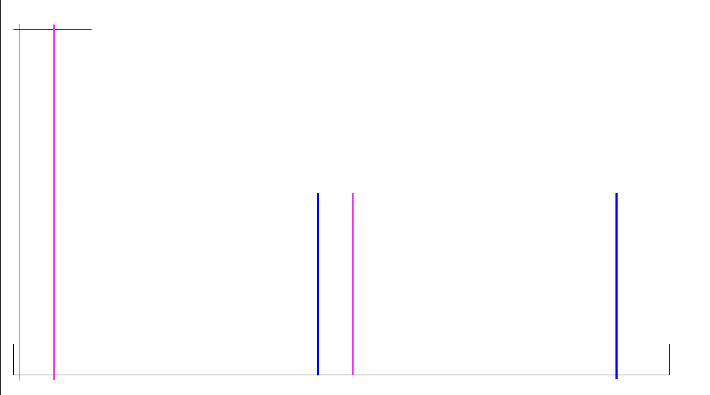
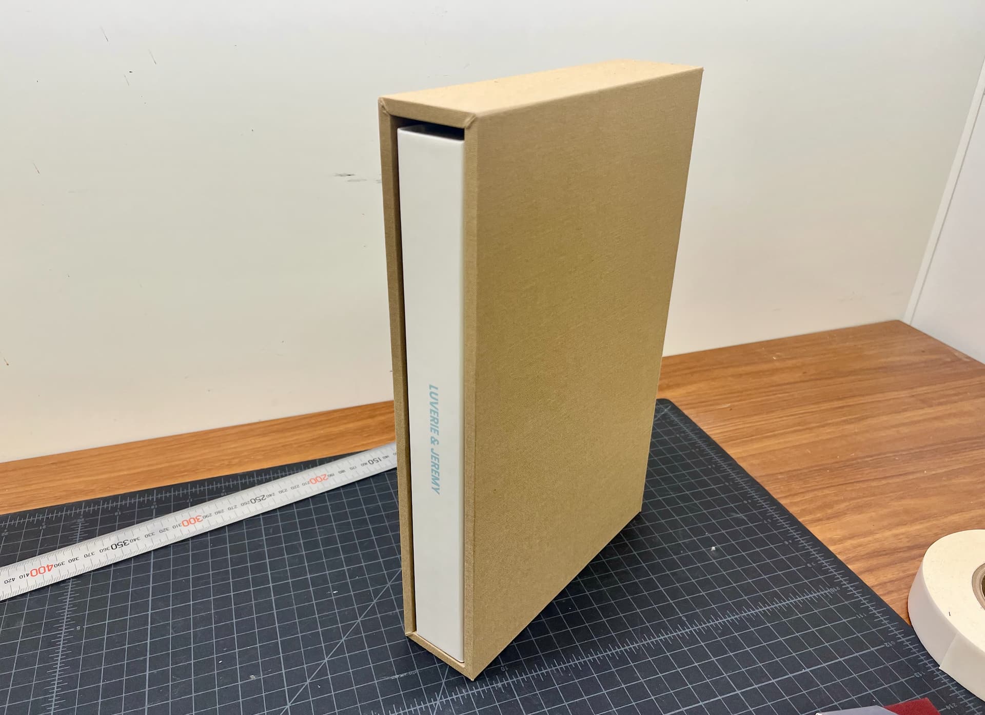
So, I am looking for a program that you can input the H x L x W measurements of an object (a book) and it creates the layout of a book box (Slip-case). The number of box sides and there relation to the book will stay the same, but as the book’s page count changes so does the width of the book and box needs to change. I ran the math on manually building each file and it would be around 180-200 individual files. I’ve attached a photo of the product and an illustration. The material is MDF and the tool paths are a combination of V-cuts and square end mill. The blue and magenta lines are the lines that would have to move based on the book’s width. The goal is to keep the 4 panels that are side by side to stay connected the 5th panel that sticks up on the left is the back of the box and laid out so lines only have to move left or right.
Does anyone have thoughts on this?
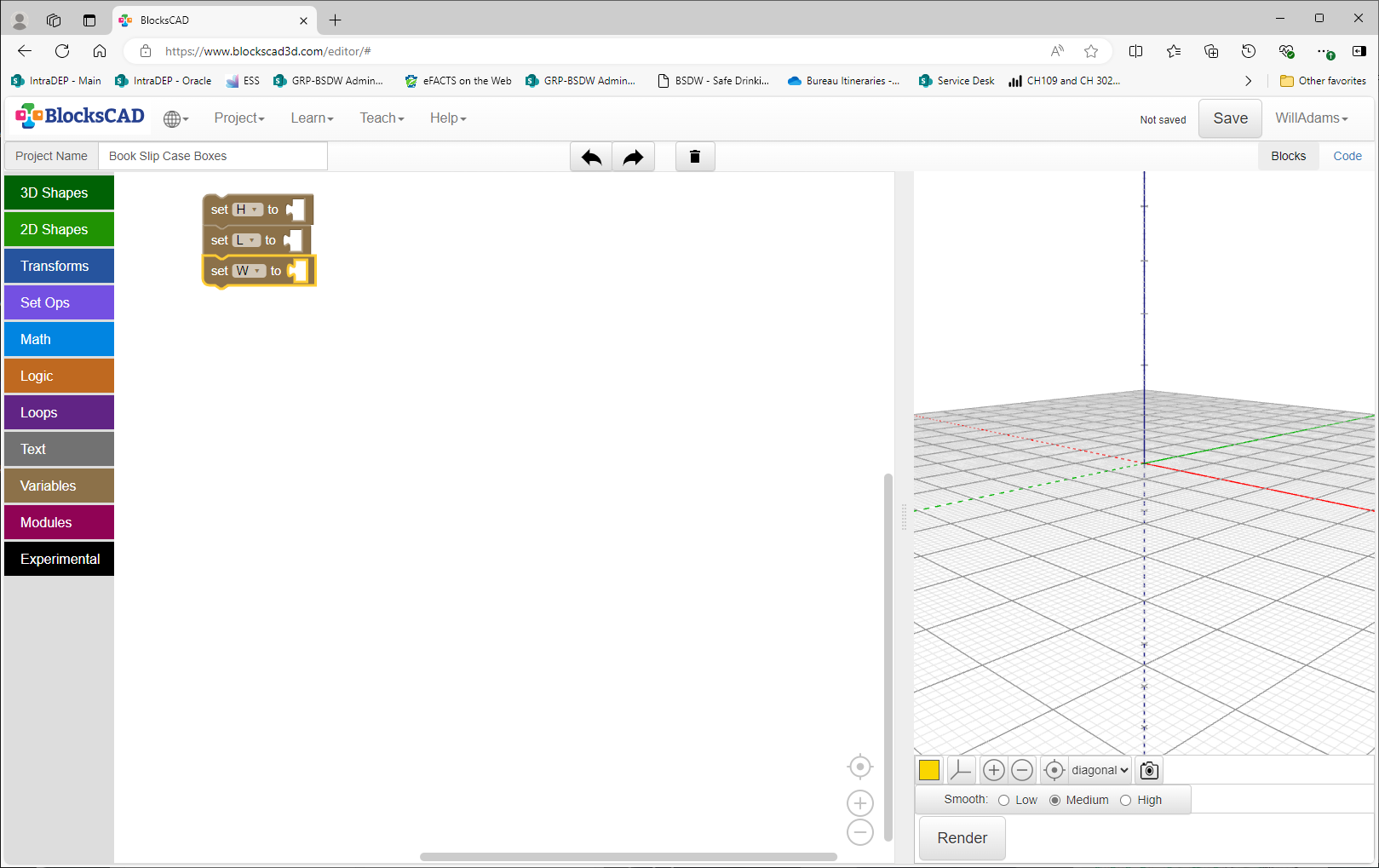
This is quite simple in BlockSCAD:
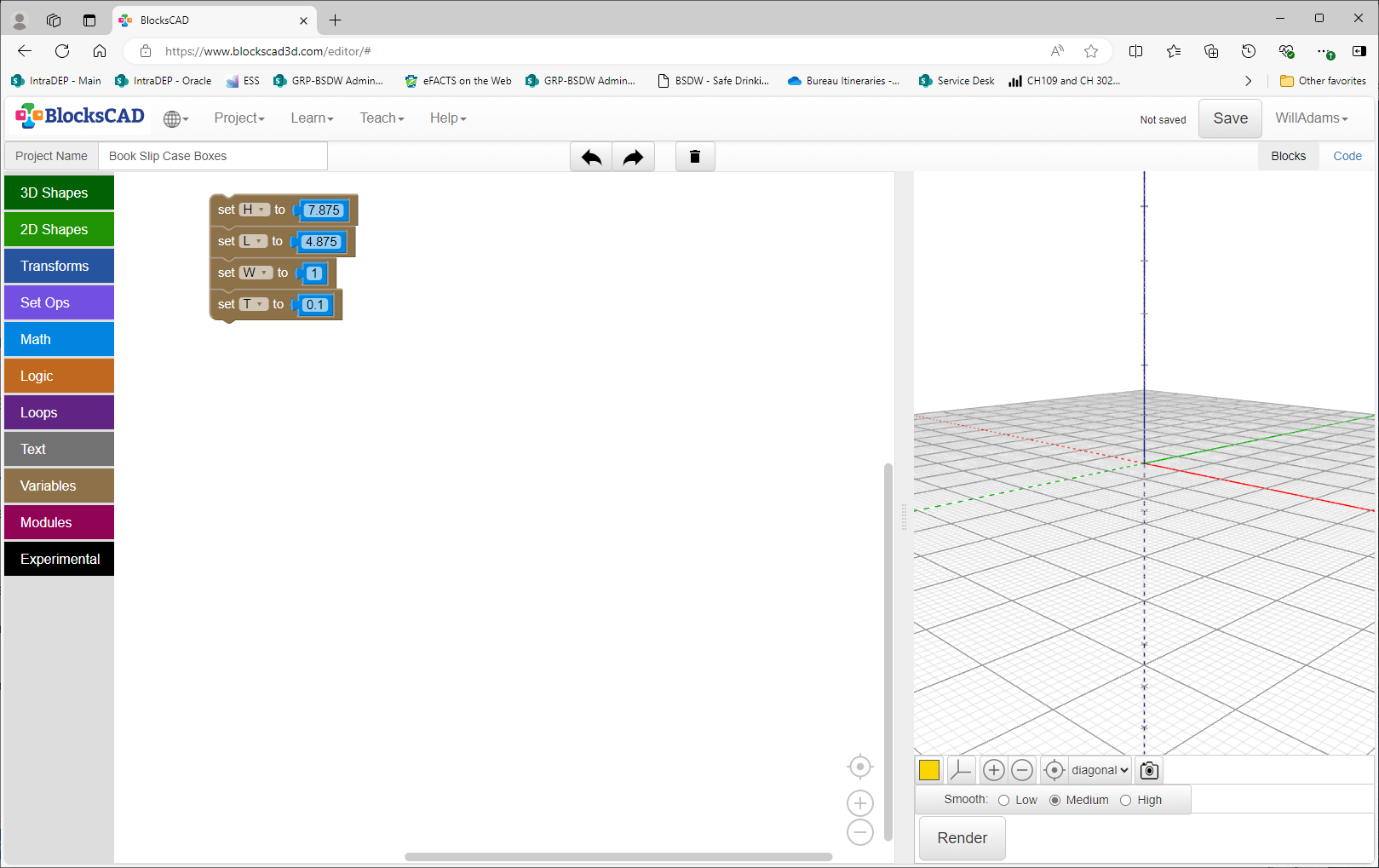
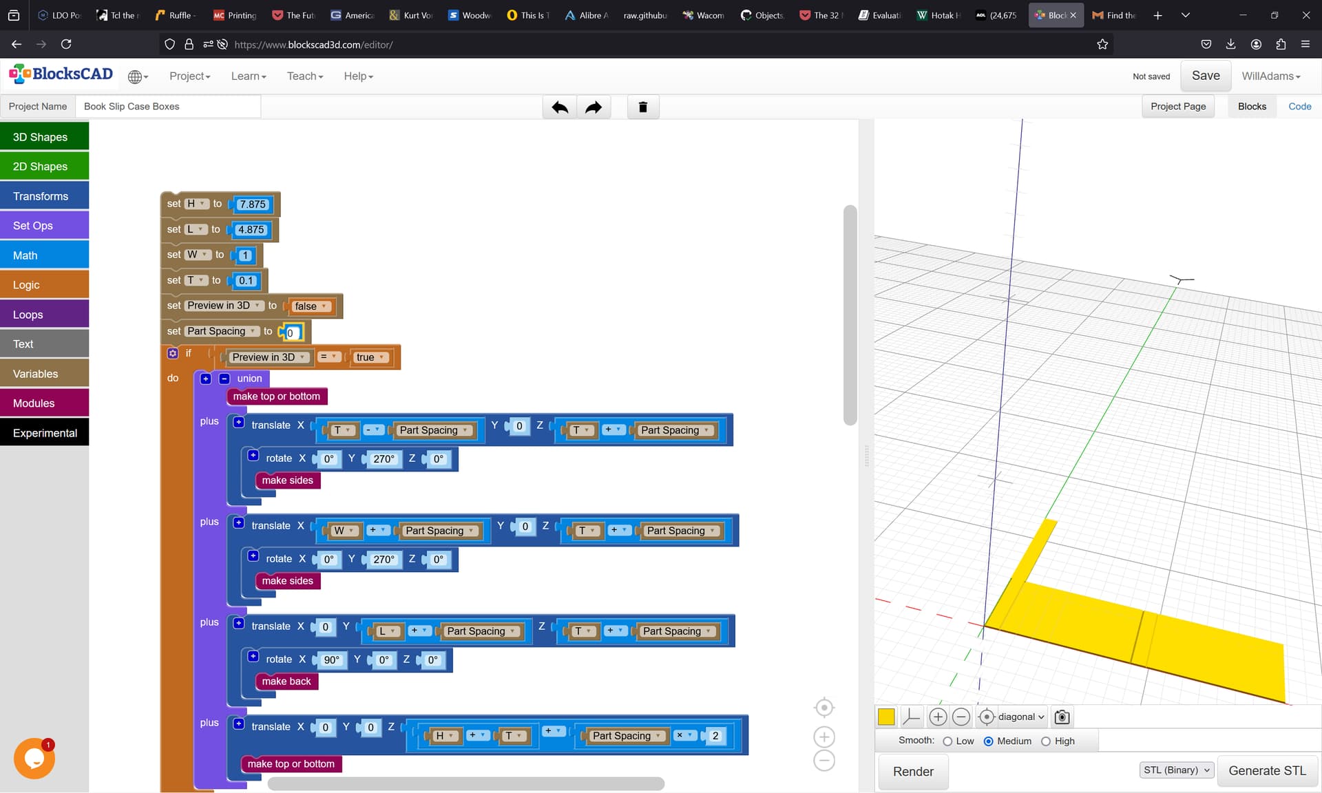
First, set up the variables:
and fill in some sample values:
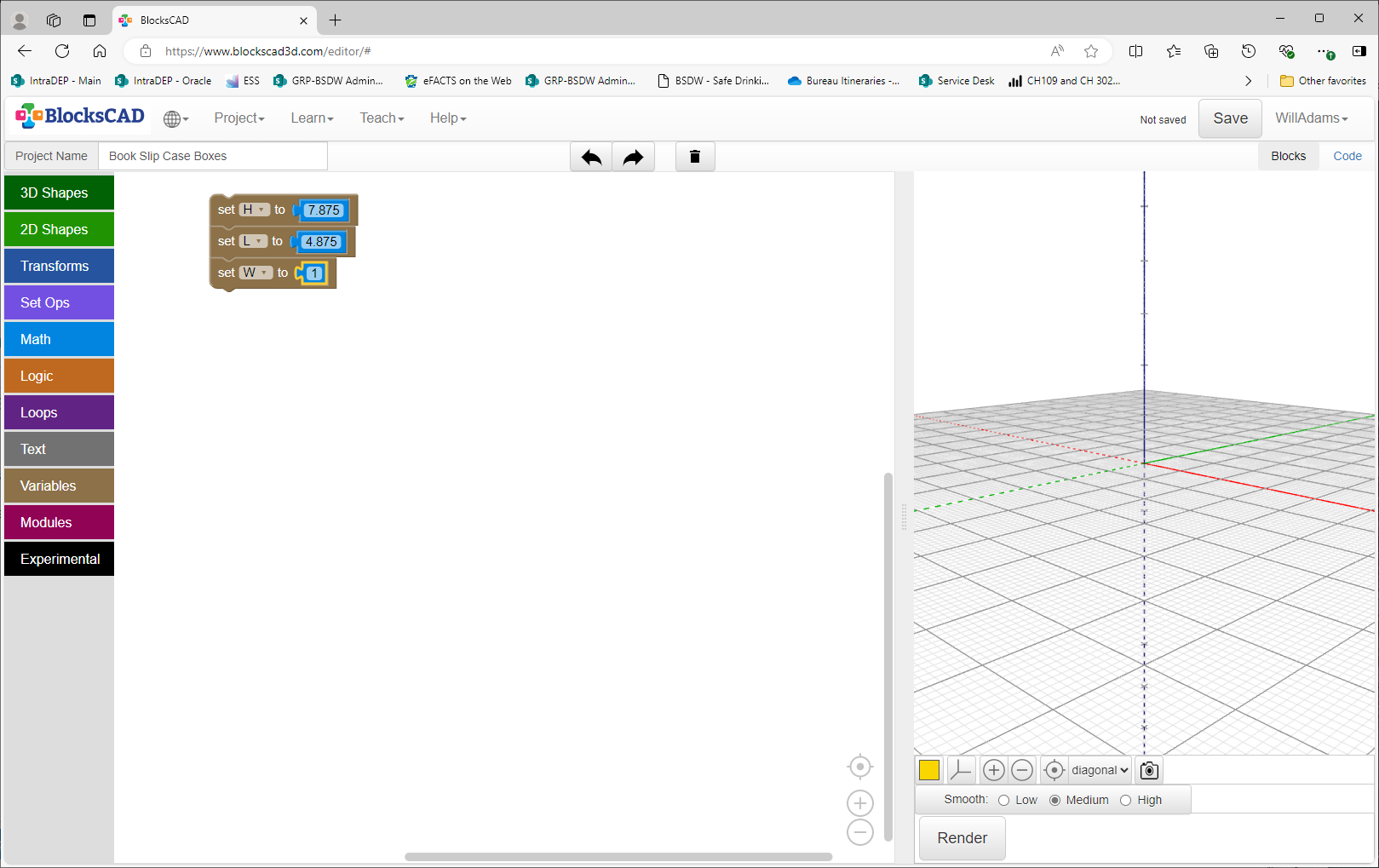
(dimensions were taken from a copy of Okakura Kakuzo’s The Book of Tea published by Charles E. Tuttle)
For simplicity, we’ll assume 100 pt. binder’s board (0.1"):
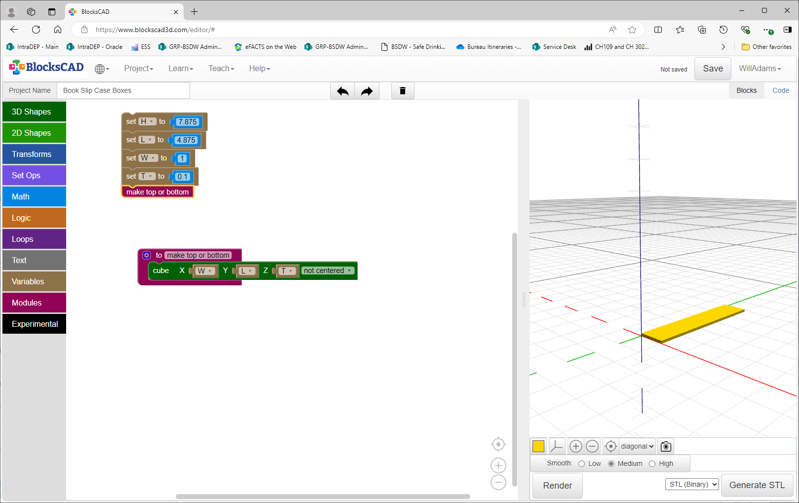
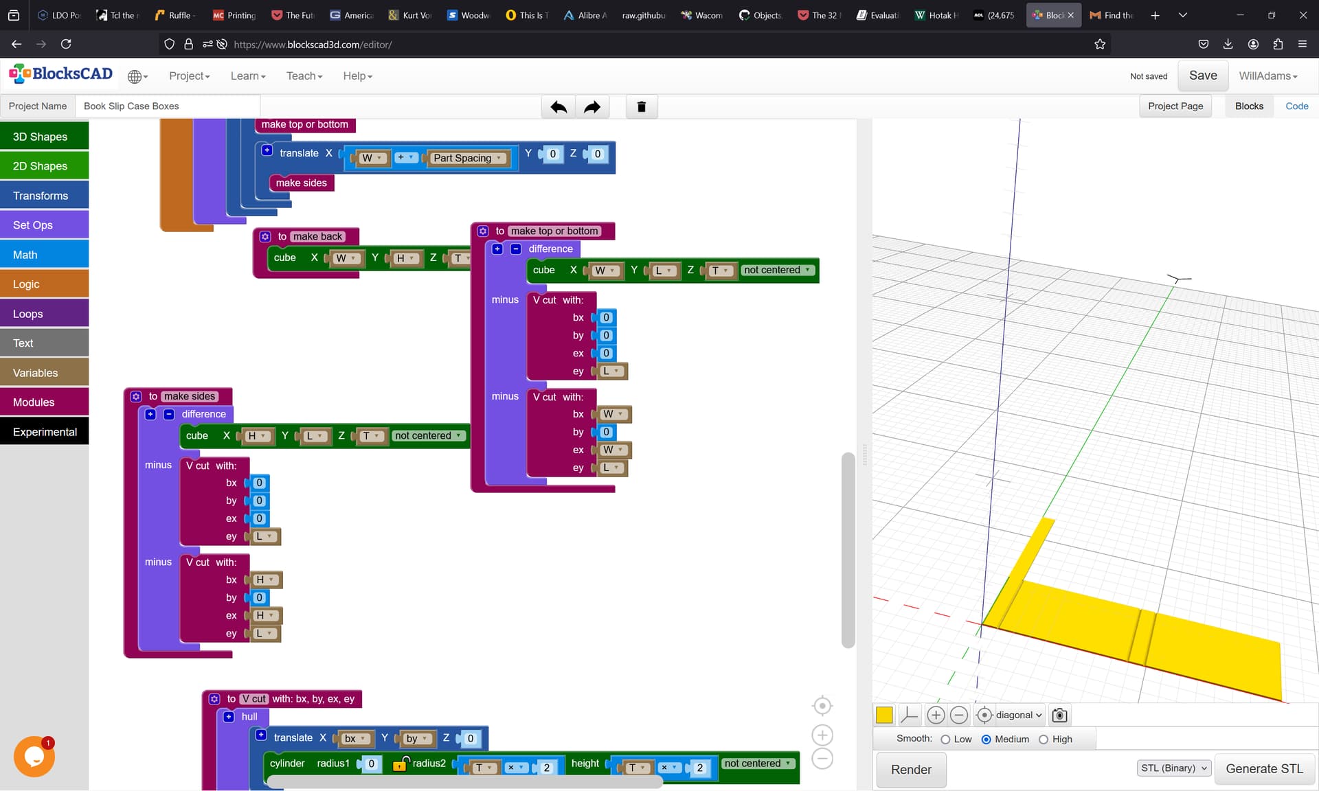
then we make modules for each portion:

which we then use to make the first part:
Repeat for the other parts…
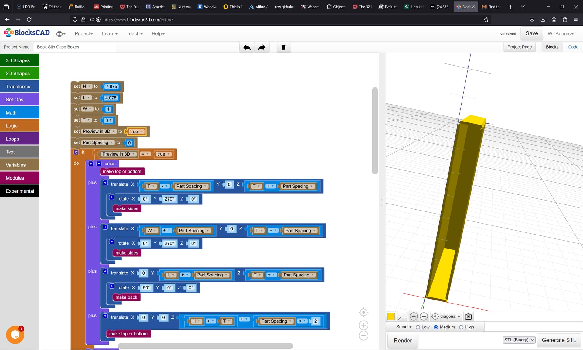
Note that we will probably want 2 different views, a 3D preview to confirm things, and a 2D layout for cutting, so we add a pair of variables to accommodate that:
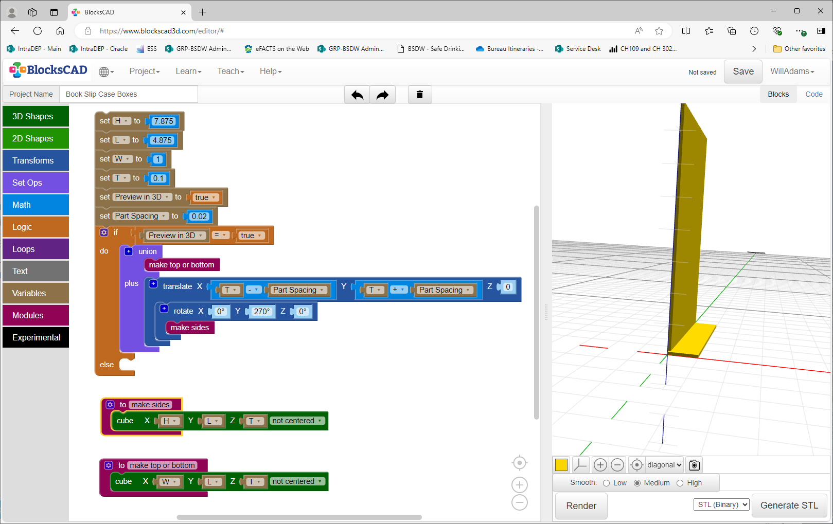
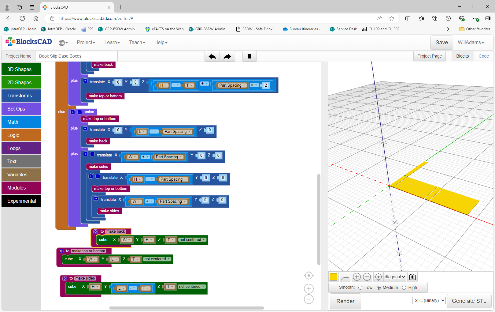
then fill in the balance of the parts:
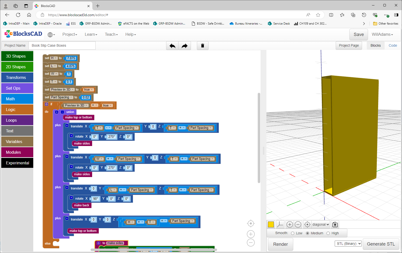
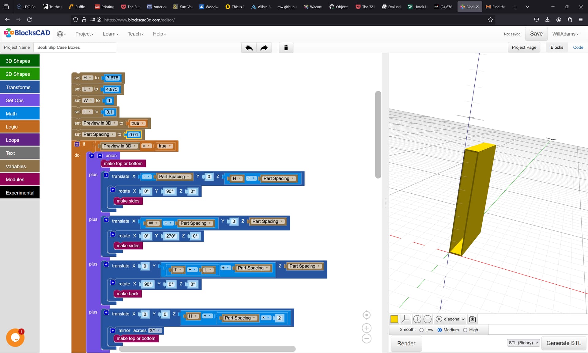
Verify the layout by increasing Part Spacing to be twice Thickness:

(and make any necessary adjustments)
then lay out the parts flat…
Note that one can nest Translate statements:
At this point one has OpenSCAD code which may be pasted into OpenSCAD:
and have a projection() command added to allow exporting a DXF — I’ll see about putting this up on Github so that we can use an on-line version of OpenSCAD to allow that.
//!OpenSCAD

H = 7.875;
L = 4.875;
W = 1;
T = 0.1;
Preview_in_3D = false;
Part_Spacing = 0.2;

module make_back() {
  cube([W, H, T], center=false);
}

module make_top_or_bottom() {
  cube([W, L, T], center=false);
}

module make_sides() {
  cube([H, (L - T), T], center=false);
}

if (Preview_in_3D == true) {
  union(){
    make_top_or_bottom();
    translate([(T - Part_Spacing), 0, (T + Part_Spacing)]){
      rotate([0, 270, 0]){
        make_sides();
      }
    }
    translate([(W + Part_Spacing), 0, (T + Part_Spacing)]){
      rotate([0, 270, 0]){
        make_sides();
      }
    }
    translate([0, (L + Part_Spacing), (T + Part_Spacing)]){
      rotate([90, 0, 0]){
        make_back();
      }
    }
    translate([0, 0, ((H + T) + Part_Spacing * 2)]){
      make_top_or_bottom();
    }
  }
} else {
  union(){
    make_top_or_bottom();
    translate([0, (L + Part_Spacing), 0]){
      make_back();
    }
    translate([(W + Part_Spacing), 0, 0]){
      make_sides();
      translate([(H + Part_Spacing), 0, 0]){
        make_top_or_bottom();
        translate([(W + Part_Spacing), 0, 0]){
          make_sides();
        }
      }
    }
  }
}
(note that the variables were moved to the top of the file so that the Customizer will work)
It will be necessary to adjust a couple of the calculations, then work out a suitable set of geometries for making the toolpaths — the above is intended as a proof of concept of one possible approach, and not as a finished thing.
The MakerCase site is a good tool for making boxes. You have the edge joint choices of flat, finger and t-slot.
Thanks Will, this is more than helpful.
Thanks for the info!
My pleasure!
For a mitered design, it is pretty simple to add the V element, and then adjust the spacing to take into account the closer positioning that allows, just add a V cut module:
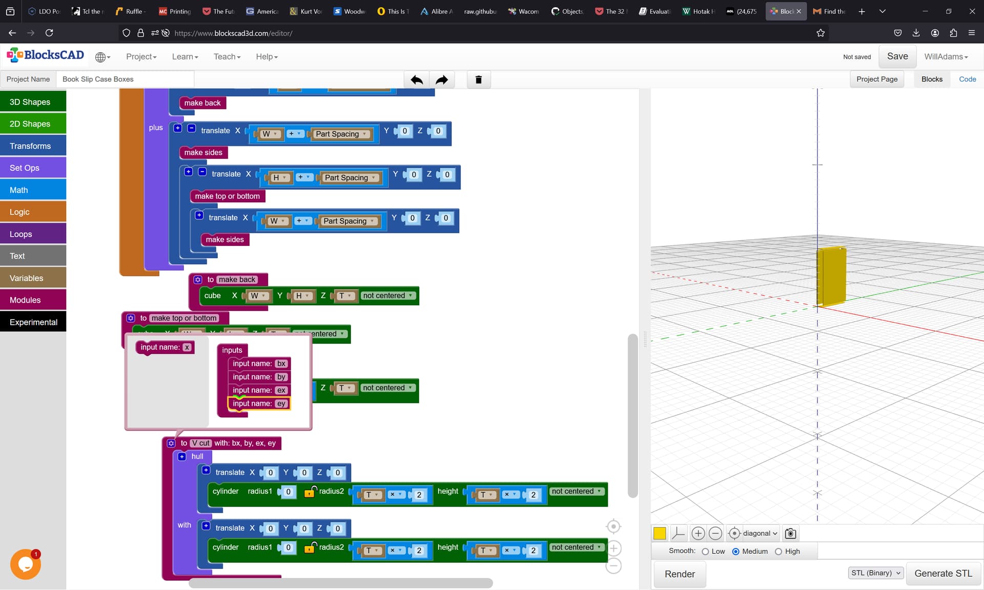
and add it to the various parts modules:
which if we then preview in 3D:
requires a bit of additional rotation/mirroring.
It should look something like:
The issue is that when exporting a DXF, OpenSCAD only does closed regions, so it’s not quite possible to directly create a file which may be opened and then have toolpaths assigned without any sort of editing since open paths and intersections are not allowed.
If you’re willing to use Python it should be able to work up a file which directly exports to DXFs — this is getting off-topic for here, so let me know in a PM.
File is at:
Try this site. MakerCase - Easy Laser Cut Case Design
For an examination of the difficulties in using such designs on a CNC (rather than a laser) see:
If you’re willing to consider Python programming, two options are:
https://boxes.hackerspace-bamberg.de/boxes.py/FrontPanel?language=en
or
which I have working again on my machine (at least for making DXFs).
If you’ll give me a couple of dimensions I’ll work up a parametric file for them (and any other dimensions you would want to feed into it).
Lots of great information here to unpack and try out. Thank you all for the help, I’ll report back with what solution I go with.
Cheers!
This topic was automatically closed after 30 days. New replies are no longer allowed.