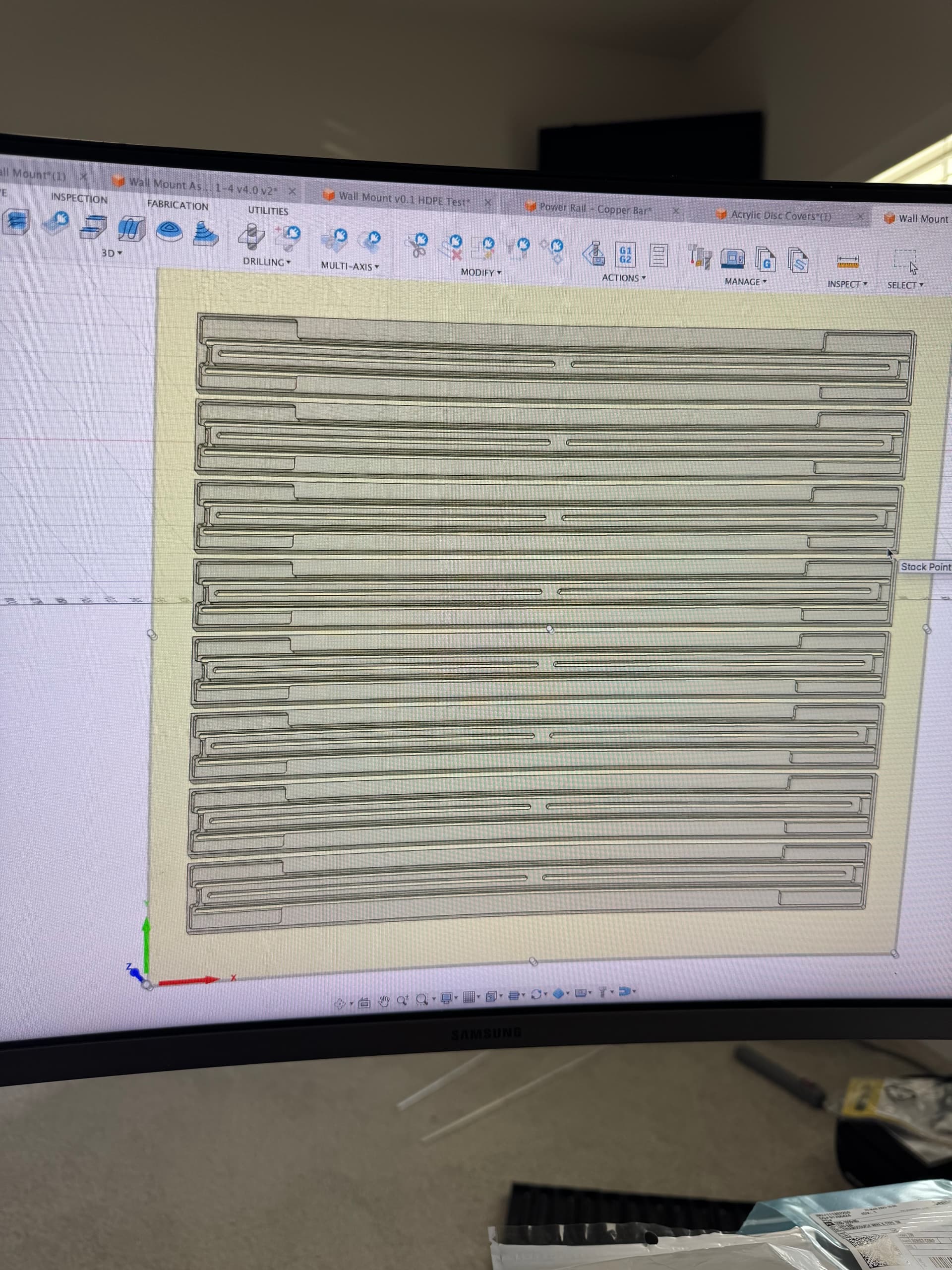
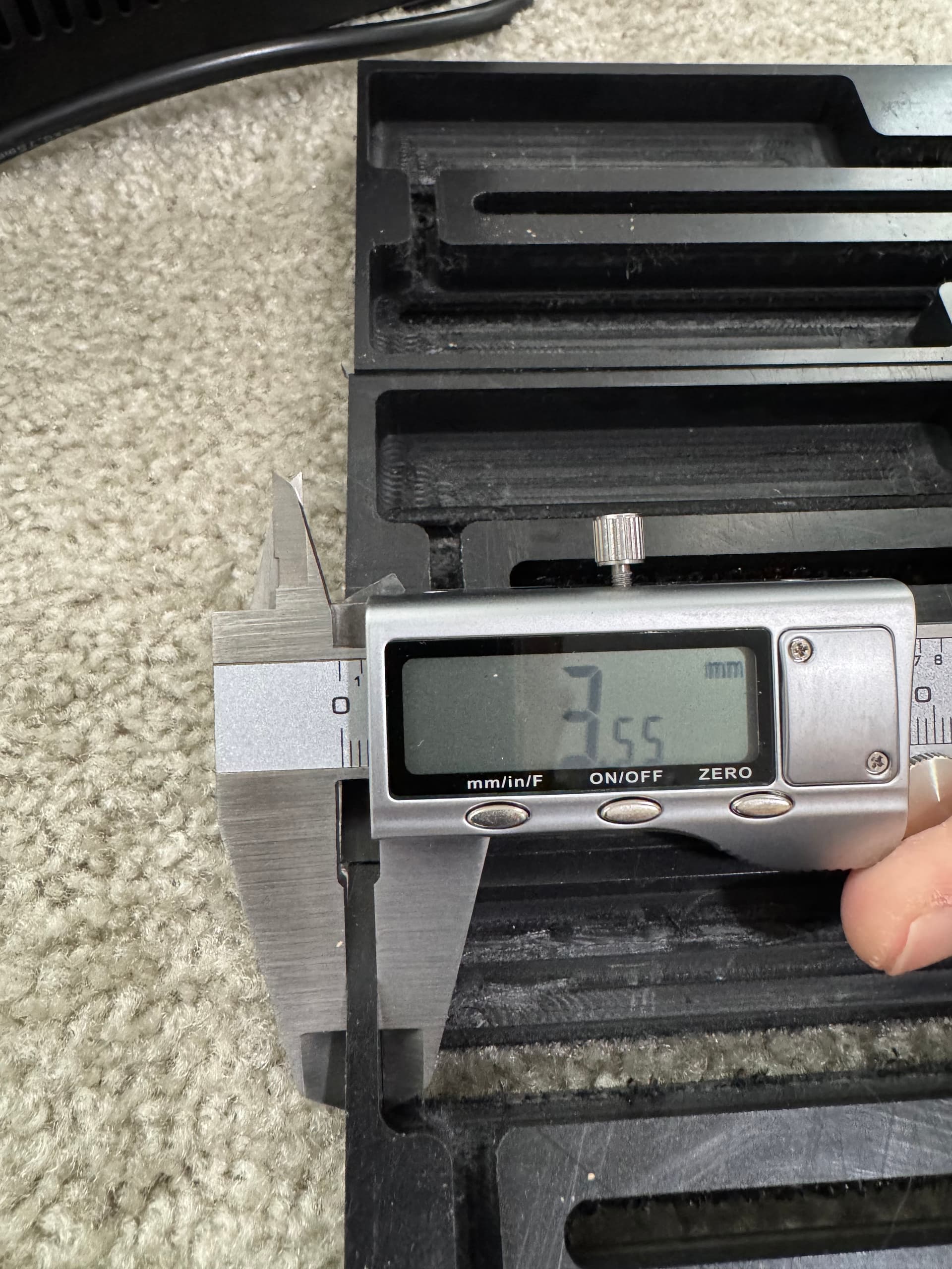
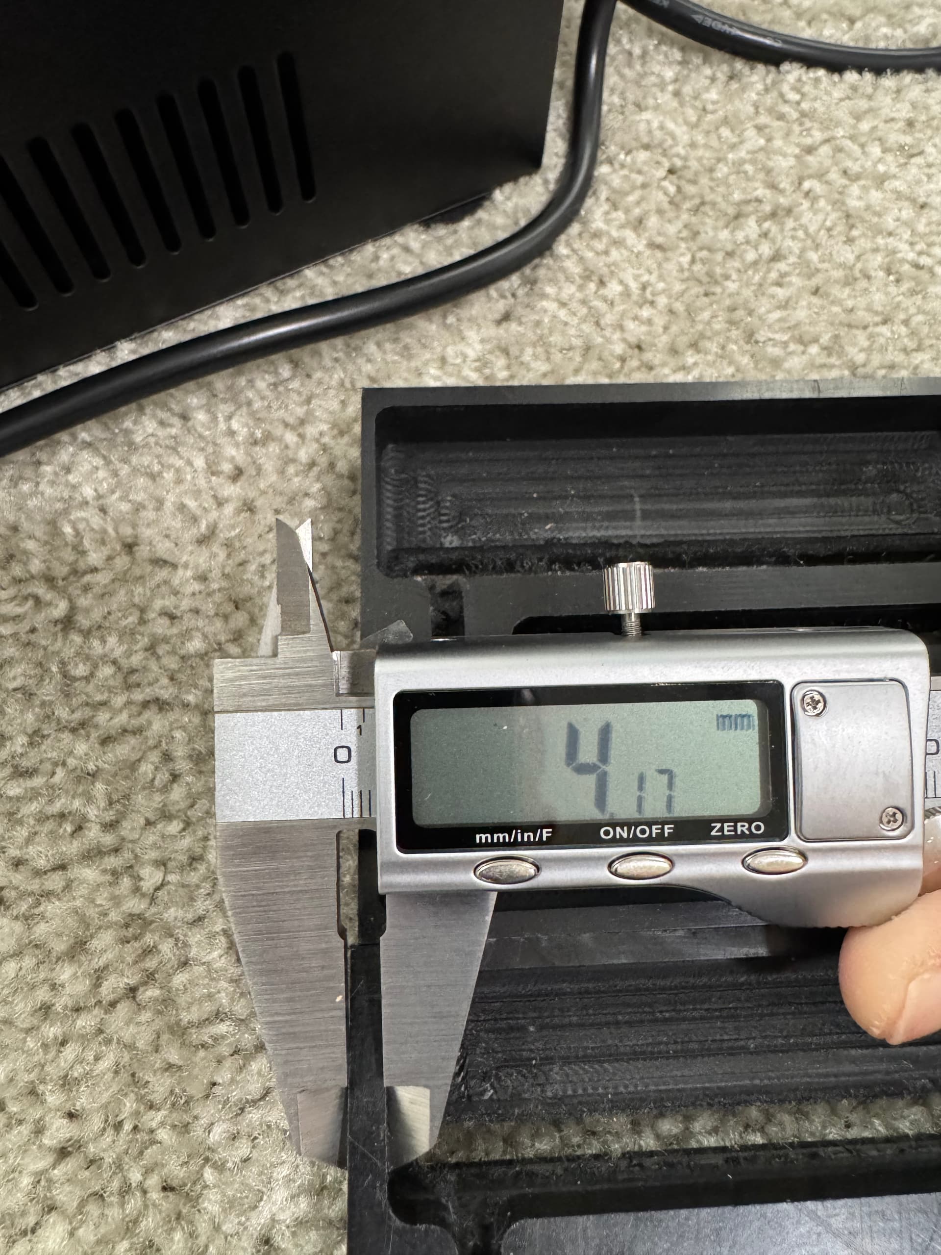
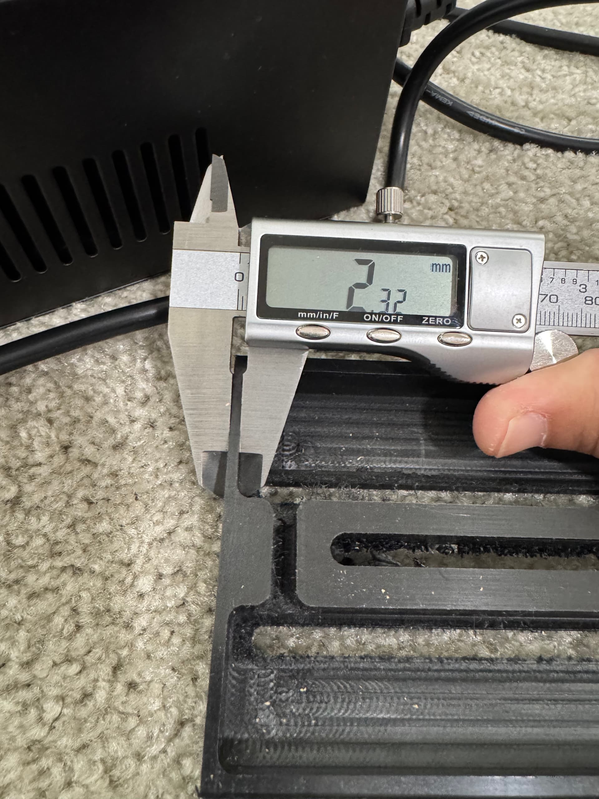
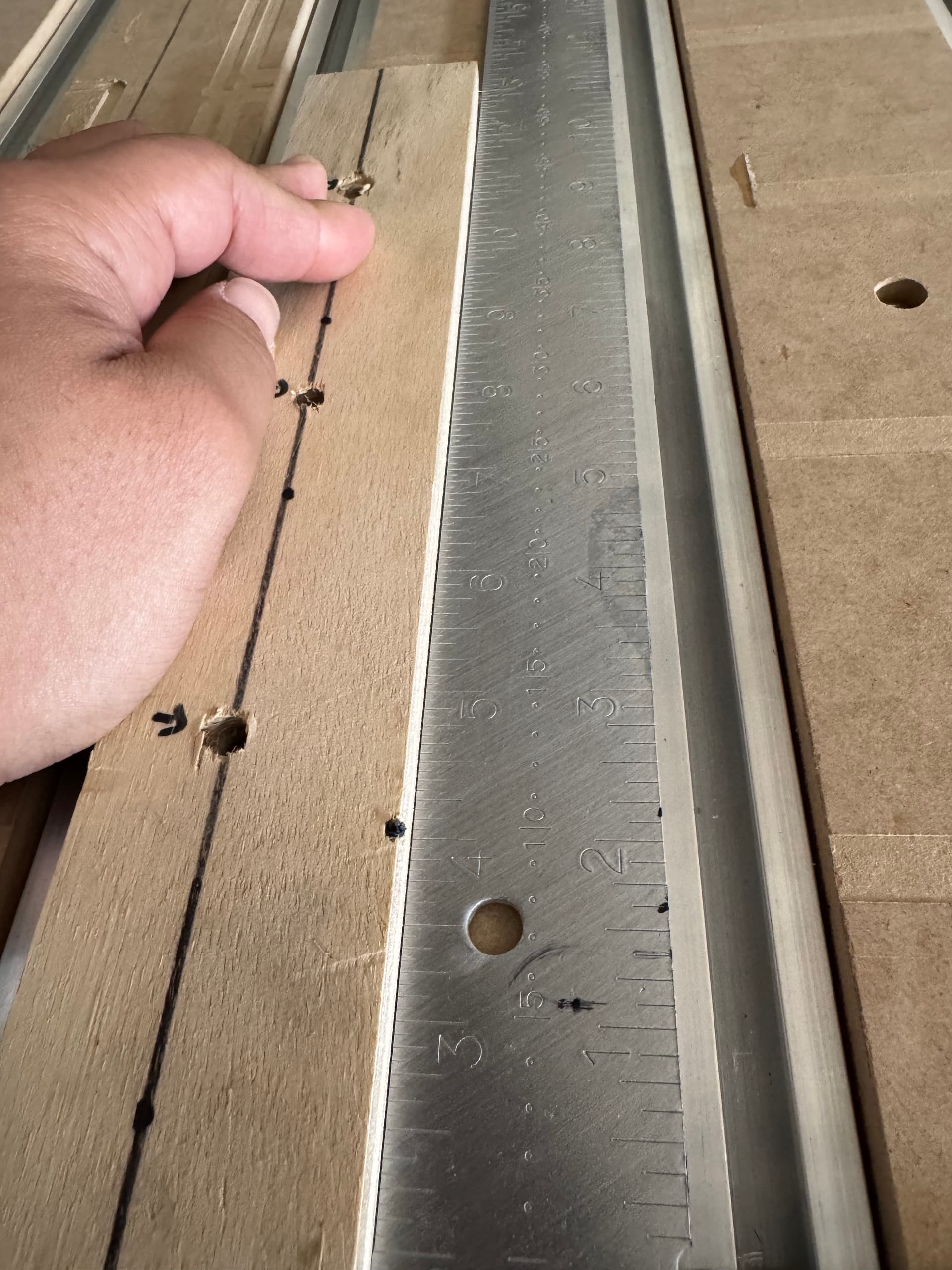
I bought a Shapeoko 5 Pro to machine a part for a product, and I’m mainly doing flip cuts. However, there’s no easy way to get this thing square, and every single cut has been off. I’m attaching a picture of a square plywood jig that I cut with the machine before machining this part in HDPE. Also, in the picture, a metal store bought square shows how the Y is a tad off and not snug (it’s more obvious in person). Additionally, I attached pictures of my intended design in Fusion 360, where the part to be machined is center to stock, and the resulting post-machined HDPE that have wildly different widths on the edges. I suspect the Y-axis on the machine is off, but does anyone have any suggestions on how to get this thing back to square?
P.S. It’s 3/4" HDPE. Also, I measured these widths out of order (the three pictures w/ caliper measurements), but if I stacked them in the correct order in which they were cut, they would all have a gradual taper. I just posted these as an example.
P.P.S. Carbide support has not been helpful at all, and I’ve given up on them. After two 30-minute calls about this issue, they just attributed the off cuts to my set up, which has never been the case.
seems too much to be sequentially done, you didnt change the order or is this first and last. My thought is you are losing steps, what kind of cutter and feeds and speeds are you using? HDPE usually doesnt get ordered over 1/2" in industrial plastic shops, are you sure it isn’t UHMWPE? Which would only add to the likelyhood of losing a step.
It’s 3/4" HDPE. Also, I measured these widths out of order, but if I stacked them in the correct order in which they were cut, I bet they would all have a gradual taper. I just posted these as an example.
Did you square the machine during the building process?
Did you check to see if your material is square to the axis of the machine and NOT a point on the bed? In any machine shy of six figure or higher, full industrial machines set up by factory techs, have I not seen a bed that is truely square to the axis of movenent.
Mechanically:
Have you kept the linear rails and bearings well lubricated?
Have you checked to make sure the couplers from the steppers to the ballscrews are tight? Each coupler has two set screws that should be on flats and two clamping screws.
Thanks! I did square the machine during the build process, but probably not well? I honestly think this is the issue. But is there a way to “re-square” without taking apart the whole thing?
I’m also going to check the rest of your ideas as to what could be causing this.
For squaring the machine the big thing is measuring the diagonals — have you tried loosening all the hardware, measuring the diagonals, then gently push/pulling into square so that all the diagonals are equal?
I’ve actually done this multiple times on my machine (first was rushed in assembly, second time to get more square, third time (the charm) was after a crash so bad it knocked the machine out of square — applied a bit more effort to the hardware that go 'round).
If you’ll let us know what you have tried and what worked and didn’t work, we should be able to assist you with this on support.
Minimum you have to remove the MDF slats and loosen all of the hybrid bed, crossbeam, and gantry hardware. Then square and tighten. Since it’s a big machine I shoot for a exact as I can get across diagonals… but I accept within 1/64" on my tape measure.
Regardless of how square you get the machine, your gantry is not likely to be perfectly square to another part of the machine like the front crossbeam for instance. If you need to locate material squarely, machine yourself a fence on the machine. That way your reference plane is perfectly square to your axis of movement.
Thanks for the experiential advice! I took the MDF off the machine and the aluminum slats, then measured diagonally. From rough measurements, I’m reading 78.125" on one diagonal, and 79" on the other, which would explain the slight shift. Something must have either happened during an early cut, or something knocked it out of alignment when assembling.
Looks like the machine is out of square. From rough measurements, I’m reading 78.125" on one diagonal, and 79" on the other, which would explain the slight shift. I’m going to wait til my wife gets home, then I’m going to measure the diagonals again, again, and then again before tightening down. Thanks!
I just noticed you work at Carbide. I’m not sure why your design engineers didn’t incorporate a self-squaring set-up. For example, the four base frame tubes should have either a black mark to indicate that the machine is square (cheapest method). OR, better yet, those four base frame tubes should actually have cut outs on each side, for both gantries, to ensure that the gantries are seated correctly / always square.
Here’s my input from working aerospace machining and having been there and assisted on the set-up of machines up to $1.6 million, 5 axis machining centers with 50 pallet hoteling systems and 200+ tool changers…
Nothing you do in the process of a complex assembly will assure squareness. Everything has tolerances and a small variance across the size of a S5 Pro 4x4 makes for huge differences once assembled. Multi-million dollar machines being installed involves a highly factory trained tech that comes out and spends a week or two setting the machine up. Shims are involved, and the techs are trained in metrology. Ff an operator crashes the machine and sends it out of calibration, there’s a chance the machine is down for weeks until a tech comes back out. I know a Shapeoko isn’t a multi-million dollar machine, but I’m using that example to illustrate that no matter how precise the individual parts are machined, you cannot avoid setting up a machine properly.
There is a phenomena in engineering design called “over constraining”. Basically you try to engineer an assembly for everything being perfectly nominal, when nothing is. Variances always exist and have to be accounted for. So marks across a 1" extrusion will not help over 4’ of machine. And machining reference surfaces or adding precision pins for the machine being nominal will over-constrain a machine that is even a few thousandths off of nominal and make things worse.
That is my over complex way of saying we all have to do things like squaring a machine…$5k machine or $2 million machine.
I’m not sure why your design engineers didn’t incorporate a self-squaring set-up.
Is the set-up of the 4 Pro different than then 5 Pro? On the 4 Pro, the instructions were to basically move the gantry to the front of the machine while the hybrid table and other bolts were in place but loose. After making sure the gantry is touching both front Y-axis end plates, tighten things down. That worked for me, second time around anyway as things shifted the first time as I tightened things down.
Yeah, I did that the first time, but it ended up not being square. I’m not sure what happened, but after meticulously measuring a couple times with someone else, it’s fine now? I tried a couple flip cuts, and they’re still off by like ~0.5mm in the x direction, although everything is “square”. I’m not sure what’s happening tbh.
I feel that maybe there are different things going on and you need to examine each independently.
In your first post I’m not sure what the metal framing square is measuring. The measurements showing a taper in one side wall (Y-Axis) could be a stock positioning error - did you check the opposite side wall for the corresponding taper?
What I would do first is, on the machine, cut a square out of the middle of a piece of scrap MDF. Measure that to see if X and Y are the same dimension and also measure the diagonals. If X and Y are the same but the diagonals are different, then your machine is indeed cutting out of square, and if you mark the piece before removing it from the spoilboard you should know which way to tweak the machine after loosening enough bolts.
If the diagonals are the same, then your machine cuts square and you should be looking at other things to explain your other results.