Been using CC and really enjoying it for 2.5d stuff, but was hoping for some help understanding the toolpath “Offset Direction” settings. Can someone please explain the differences between Outside/Right, Inside/Left, & No Offset?
Are these just different terms for Climb and Conventional milling? Or what?
Every cutting bit has a diameter. Say for instance .25 inches. If you have a 1 inch square that you want to cut out, and choose Outside Right, then the software automatically accounts for the 1/2 the width of the tool and you will end up with a true 1 inch square in the center. If you choose inside, then the outside portion of the cut will be exactly 1 inch, the inside will be .25 less on all sides so it is almost like a .5" inside square. If you choose no offset then you will end up with a 1 inch - 1/2(.25) on the inside and 1 + 1/2(.25) on the outside of the cut.
This assumes you accurately put in the correct diameter bit in the software so it can calculate the tool path properly.
As a follow up, I think I see the use of cutting it on the Outside Right, ie if you wanted to make an object or a boss that is 1" square, and Inside Left makes sense if you are trying to cut a 1" square hole in a larger part, but what would be the use of No Offset? Is it just for slotting?
I tried my best to understand what you said and I actually think I do, but I’ve got a piece already double side stickied down to my table that is for a customer and I just want to be AbsoLUTEly sure that I get this right. So my question is, if I want to “pocket” 2" holes so that what’s left are “2 Inch Holes” do I use the Inside Left option???
To add to this, Inside/Outside only make sense on CLOSED vectors. With an open vector, there is no inside or outside, so you get the modifiers, Left/Right.
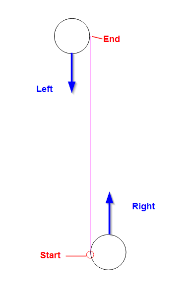
Imagine just a straight line. Normally, you might think cutting on the Right side would be conventional cutting, and on the left side would be climb cutting. CC doesn’t do this. It likes to conventional cut either way, so the Left/Right are determined by the starting end of the curve.
Unfortunately, you don’t know which end is start & which is end.
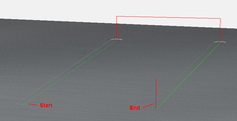
There is one small clue that works for open curves. If you create the path & simulate, the starting engage will be green, and the retract at the end will be red.
And if the vector is symmetrical, you can swap the start & end by mirroring the vector.
In the above picture, I duplicated the left vector on the right, then mirrored it to get the path to go the other way.