4 years ago I put an hdz and a 2.2kw spindle on my 3 Without this issue. Trying to do it again with a 5 and having some issues.
It’s a 2 pole 220v 400 hz spindle.
Standard hy vfd. Set for 0-5 b pwm, 60 hz, 2 pole, max rpm 24000. Min hz 20 and .5 changing it made no difference.
$30 set to 24k
Well I get 144mv from the s5 spindle connection as soon as it’s turned on which gives me 408 indicated rpm on the spindle at all times. That’s problem one.
Problem 2 is that if i use the mdinand use m3s24000. I get 12240 indicated rpm. Doesn’t sound like 24k either.
So I measure voltage across the terminals on the vfd. Vcm to vi. I get 2.49 volts. (Still commanding 24k rpm). It doesn’t matter if vfd is on or off.
If I disconnect one or both wires and measure them disconnected I get 4.95 v.
Doesn’t make sense to me.
I have tried making $31=2000 to stop the spindle from always spinning 400 rpm but that did nothing.
I love it how the admins feel they have to delete a post showing a solution to this issue while in an unsupported area. But don’t take the time to offer a solution of their own for a flaw in their product.
I said it once and I’ll say it again. Carbide used to support modifying machines. This forum is full of posts showing this. That seems to be gone.
I had every intention of ordering another 5 pro 4x4 in the spring. I’m not sure about that anymore.
Let’s try this again but I guess I have to modify the text to not provide a reference to any specific vendor…
Some other vendor that happens to sell CNC related items has this note on their product page:
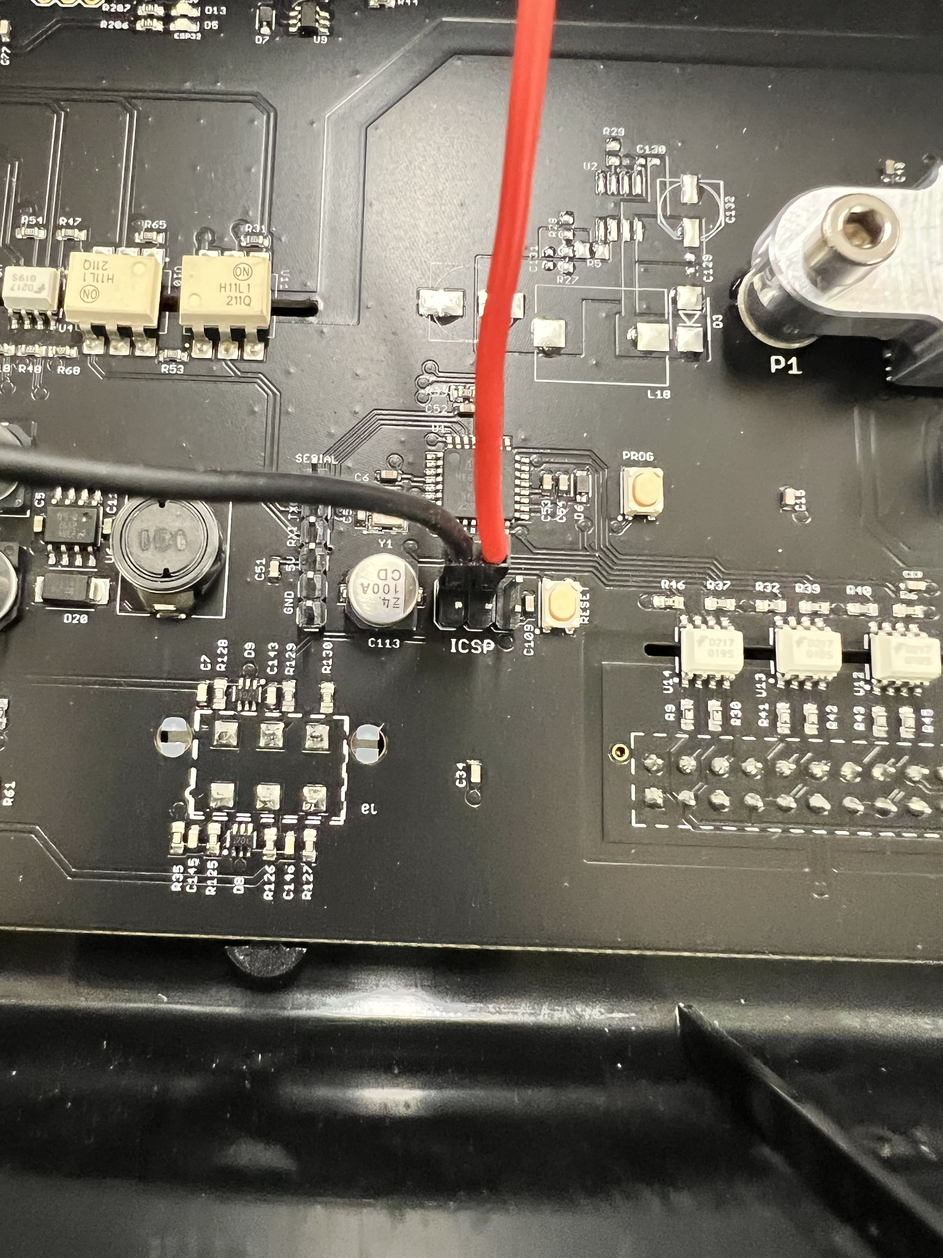
Shapeoko 5 Pro’s Warthog controller has an extremely poor quality PWM signal. Plugging into their spindle port will result in incorrect RPM commands coming from the controller. An ICSP header is available within the controller that provides a cleaner PWM signal. [Some Company] have designed a [pigtail]([link removed]) (purchased separately) that is working great in our testing. Reach out to us via [email@removed]([link removed]) to learn more.
Hopefully that has been sanitized enough to leave the answer out here.
I would love to hear any comment from C3D on the claim that the signal is poor and whether they think that using ICSP port is a good solution to those having problems with the PWM signal.
While I only had Radio Fun. when I was in the Air Force, I’m mystified as to how a PWM signal of “poor quality” is addressed by a “simple pigtail” so as to become a usable signal.
EDIT: Moreover, the signal works fine with our VFD spindle kits, which is the intended usage.
Hopefully a qualified electrical engineer will be willing to speak to this.
To demystify it, I think the “simple-pigtail” is connected to a different part of the controller (ICSP header) so it’s a physically different connection (above and beyond whatever differences there may be on the board between the ICSP header and the “std” PMW header). But I’m an ME, not EE so all just guess work on my end
So the translation would be that the specialized signal afforded by the BitRunner connector for use with the Carbide 3D BitRunner or VFD spindle kit was characterized as “poor quality” despite working perfectly well with the accessories which were properly designed for that signal, and that instead, this connector is bypassed with a connection to a different connector by the pigtail.