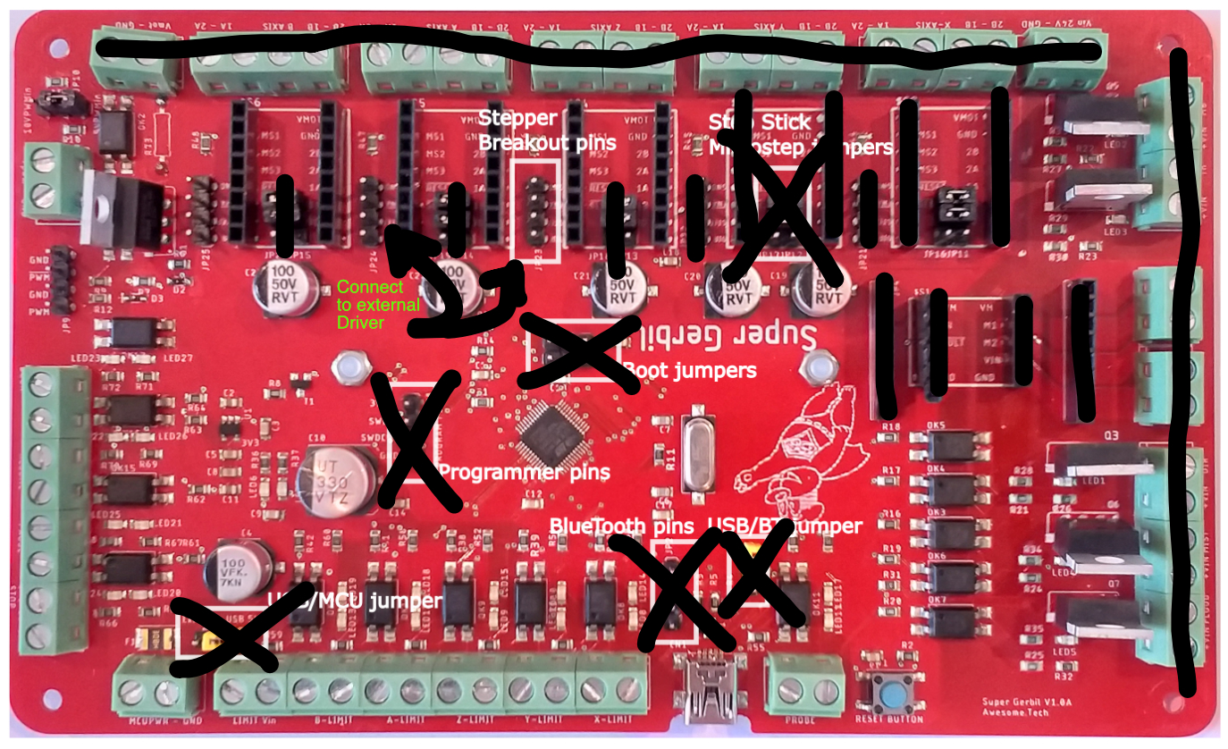
I had the same concerns, and there isn’t a way (yet, anyway) to slave two of the drivers together in software. I use external drivers (if you look at the photo, you can see the wires coming off the “external” connectors.
An external driver requires:
Enable (this comes from the board - in the case of this board, they are always enabled)
Step/Pulse (this comes from the board)
Direction (this comes from the board)
Ground (kind of obvious)
+Power (from an external power supply - in the case of this board, you could use the same power you would have otherwise used as the input to the board for the drivers. Each axis needs -a- stepper driver. It could be external, or one of the onboard sockets, or a mix of the two (but if using external for an axis, take the onboard driver module off).
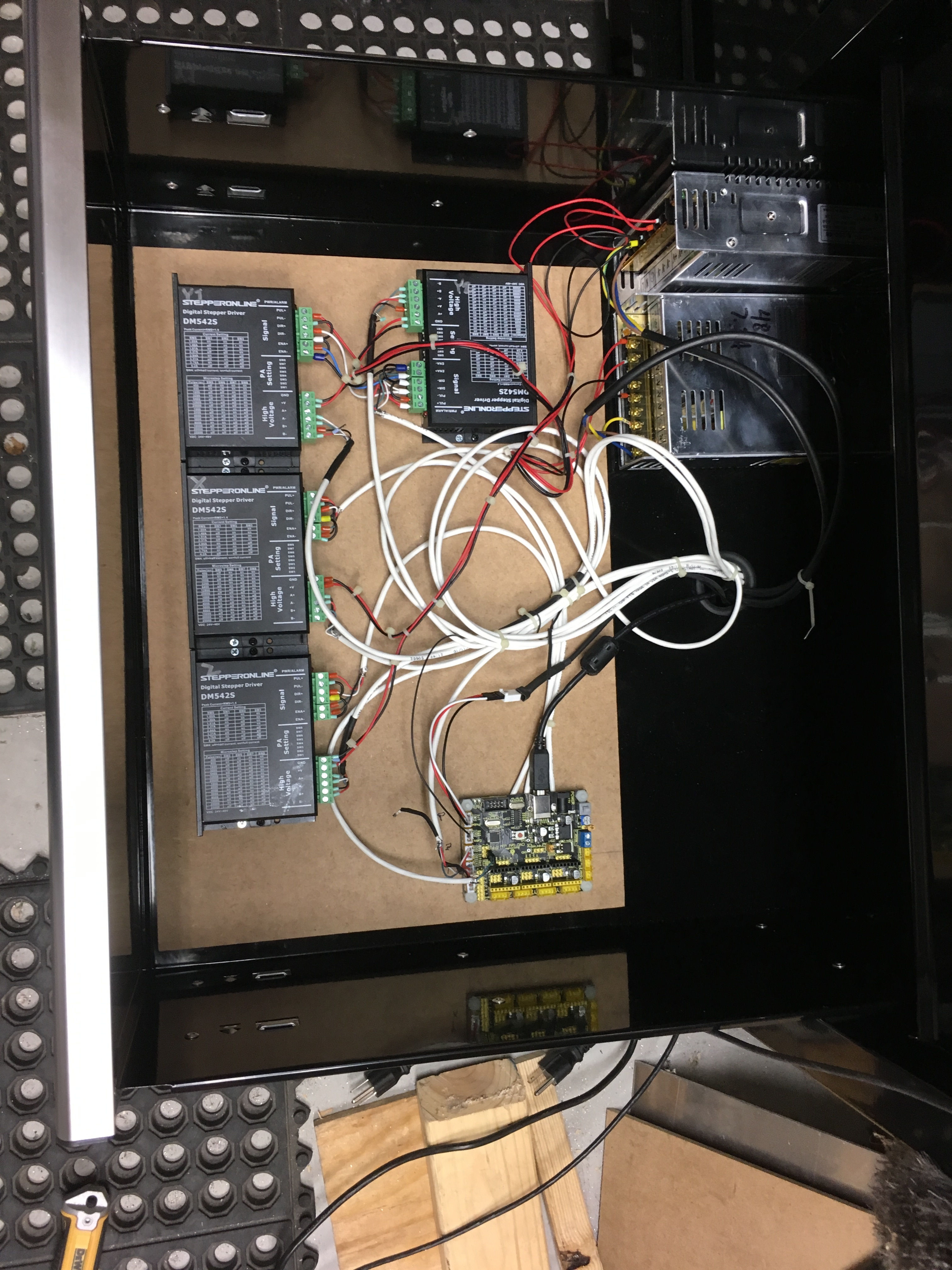
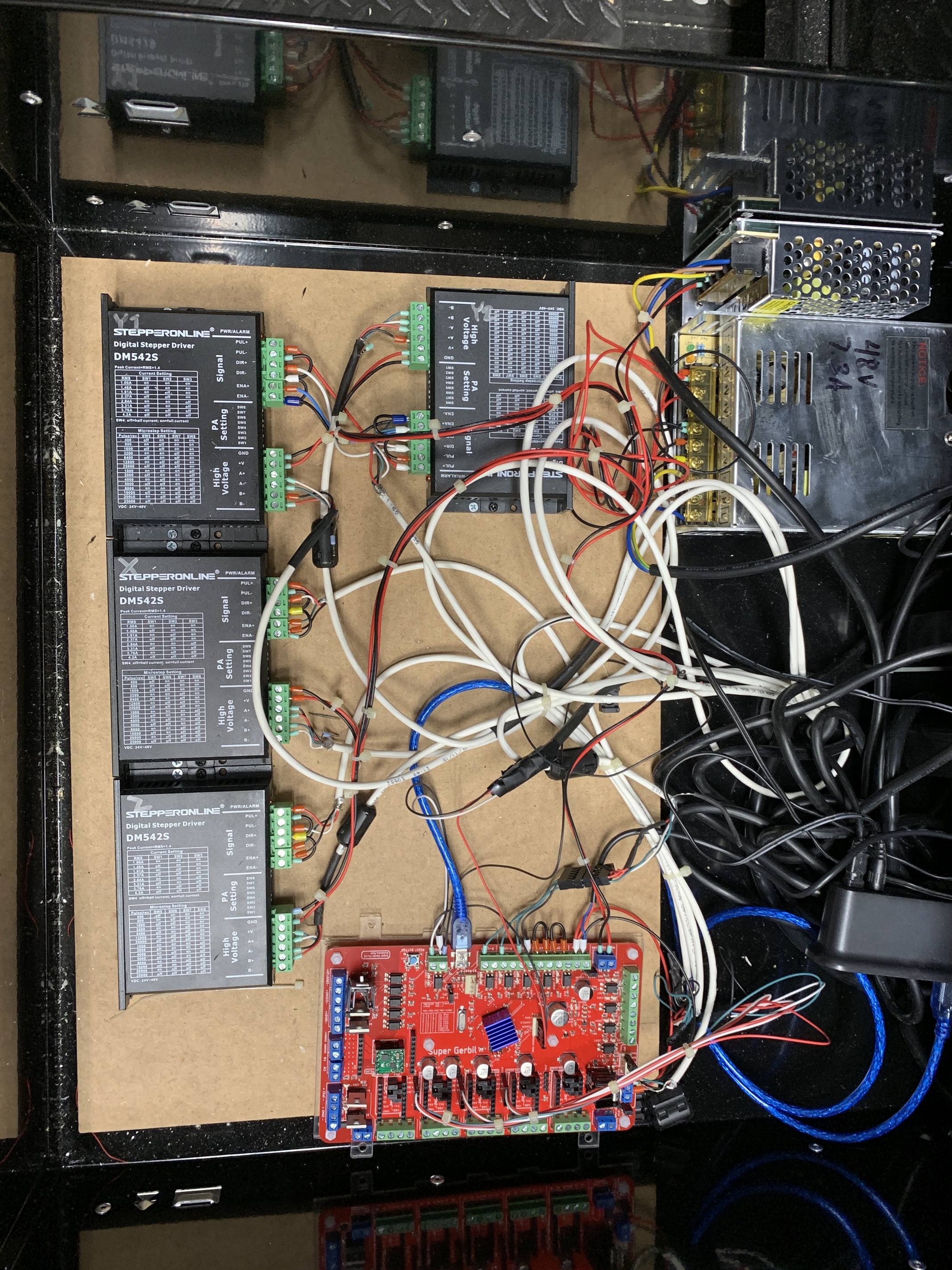
In the photo, you can see the wire bundles coming off the right side of the board. These are all going to my drivers, which are offboard. The jumpers under the driver sockets have no function in this setup, the microstepping etc is set directly on the stepper drivers. In the photo below you can see the old setup. The little board is the arduino w/ the breakout. The stepper drivers are the black boxes to the left - the top two are the Y axis (left and right) You can see their wires go under the arduino complex (they pass directly under the USB port), where they’re soldered to the back of the board (it was more stable than the connectors on top) . The drivers weren’t very expensive, but it requires a bit of work to build out the harnesses/wiring/etc. Not hard, just time consuming.
I did change from two 48v PSU’s to one (I’ll see how that works out), and added a 5V 3A supply for the board and run it from that instead of the USB power (because…reasons?)
Old setup - the new supergerbil board replaces the board in the lower right corner.
The tip: Choose the cheapest - if you’re using external drivers, you don’t need any of the drivers they supply - the board is exactly the same no matter which package you choose, so if you aren’t going to use the polulu type driver modules that plug into the board, you don’t need to pay for them :). You’ll need to take them off anyway.
Incidentally, the board supports a bluetooth connection with an HC5 bluetooth board (check amazon). So far, I can’t get it to work. In my setup, it would be nice to not have a USB connection.
There are a couple things to know though - unplug the usb if you are going to use it, there is also a “bt” jumper to enable it. I’ve tried 3 different modules, can’t seem to get it working, but will get back to it eventually.
Yeah…It would have been SO nice to see your photo WITH a super gerbil hooked up two drive’s for the Y axis… and a zoomed in photo showing (detailing) the exact pin locations…But I guess not…I’ll wait for someone to do the above…@Vince.Fab
Because you know, it’s easy to let the smoke out of those little things…and the instructions at the super gerbil website absolutely suck for anything other than plug and play. @pauldg123
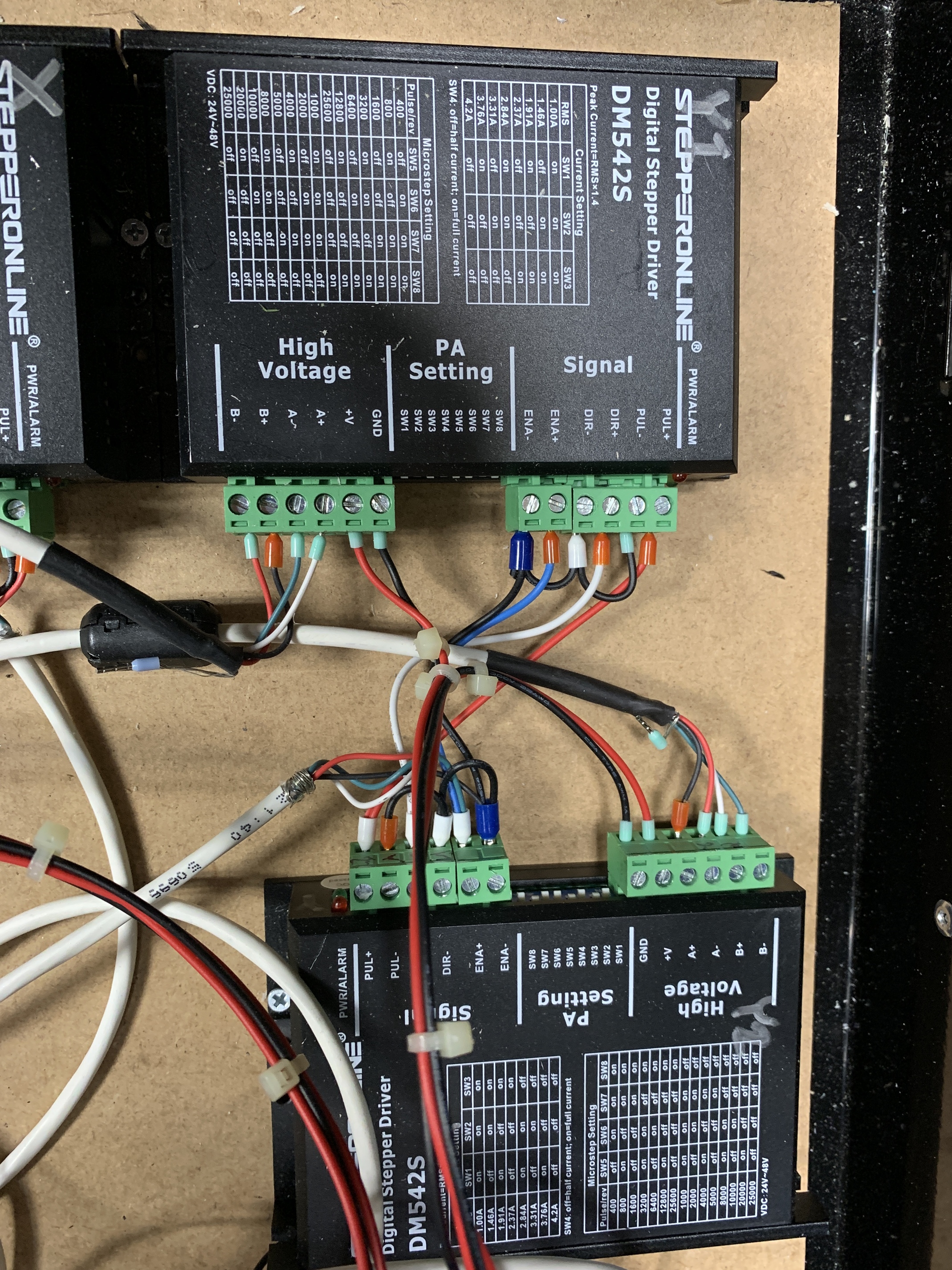
As you asked. Fair warning…kind of a mess yet. I’m using shielded cables, and they’re really stiff.
The “output” cables from the stepper drivers run out the bottom of the drawer, then up to the top of the workbench and the machine. They’re shielded. I used the same cable (convenient) to hook up the board to the stepper drivers.
Yes, actually. That’s exactly what I did with enable. In fact, it’s hard wired on the board and not actually connected to any pins on the processor. The GRBL boards are generally this way - none of them control enable in software, and that’s why when you turn on the power the machine goes “clunk” - it’s the stepper drivers becoming enabled, and the coils in the steppers locking the rotor in position.
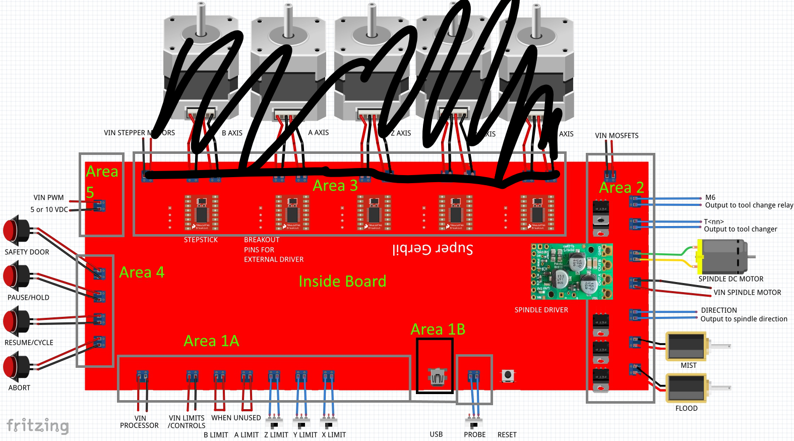
The whole thing isn’t quite as complicated as it looks. I’ll draw something up, will post here when I’ve done so.
Excellent, those are really clear and let future people trace the wiring. Super useful for people trying to get their own setups working, if/when they hit problems.
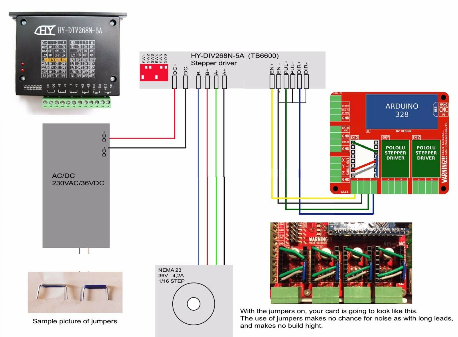
This should help, not something I drew, but it’s accurate and clear. All stepper drivers look basically the same from this regard. Use the table on the top to set the switches - this depends on what microstep method you want to use, what maximum current you need for your steppers, etc. There is an additional “external driver” connector on the sueprgerbil board with enable, clock, direction marked on it - use that to run wires to the external driver (as show in my pictures) instead of the green blocks in this diagram.
There are modules called “stepper smoothers” - these are used for 3d print applications for smoothing output and feedback. I recommend using them. They plug in, then the wires shown get plugged into the top of -that- module instead of the board connectors. (look here - the version you want looks like this, you can get them from many vendors, they’re all the same: https://www.th3dstudio.com/product/direct-plug-in-stepper-smoother-board/ ) . Mine are not installed in this set of pictures for clarity.
You feed your stepper drivers off the side pins next to the drivers, but this photo has jumpers (huh?, what and why are there jumpers now…) and this photo is feeding the drivers from the green stepper connections.
Then throw in stepper smoothers and I am not back to square one…but further back than that now.
I like it. The case is junk, don’t get that. Other than that, has been working well. There are some things I’d like to add to the software, but it works well as it is.
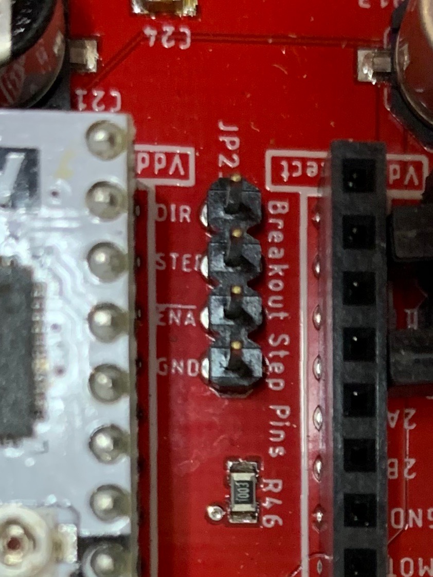
Hey Mike, with the desk finally done, it’s now time to concentrate on the 4th axis. While reviewing your instruction and instructions, you show a very clearly labeled wiring diagram, and then state “There is an additional “external driver” connector on the sueprgerbil board with enable, clock, direction marked on it - use that to run wires to the external driver (as shown in my pictures) instead of the GREEN blocks in this diagram.”
Here’s my problem:
Your diagram shows 4 wires labeled: DIR+, PUL+, EN- and EN+,
The Break out pins on MY board labeled: DIR, STEP, ENA GND
Not enable, clock, direction as you state.
So is
DIR = DIR+?
STEP = PUL+?
ENA = EN+?
GND = EN-?