Good question. i wouldn’t want to mess with it for 90 dollars difference. I would buy the one that is already engineered to fit. But that’s just my opinion. Some people like to work on the machine, I prefer to work on projects with the machine.
I’m going to chuck my 2cents in here.
I’m actually building my own Z-axis with a twist for my S3. I thought it would be cool to build parts for a CNC on my cnc. It’s not for everyone and has taken more time then buying one, but it will be cheaper in $ value and provide me with a project… Hoping to have it done over xmas if my last few parts turn up!
2 Likes
If I imagine that it must be so accurate that there is no way that any of us can do it, also $ 90 can mean other cutters.
Anyway it is something I found and I put it with the encouragement of information and will be the result of researching whether it works or not.
Good my friend you are a builder !. Is nice to see your passion !. Congratulations !.
Jose,
The Openbuilds is similar to the Z axis on the SO3 with the exception of the lead screw. It uses aluminum extrusion and v-wheels also.
The CNC4newbie Z axis uses linear guides and bearings with a lead screw.
I have considered the Openbuilds option prior to the CNC4newbie one was available , but the linear guides would likely give better performance than the v=wheels. It would be interesting to see a side by side installation and performance comparison between the two.
2 Likes
I appreciate your words, it is something that I saw and it caught my attention, from the beginning I thought that one can make this addition to S3 as our partner MrBeaver does, I think that the machinists of this forum we can do it could be more economical and interesting, the very limiting words of our friend Dustin are annoying, for that reason I have answered him, agreeing with him in the need to do a reflection in the Z axis which I see that varies the depth using the belt. I think there is an improvement with the screw.
I have seen these rails for a while. My next project will be increasing the size of my Shapeoko 3 by using these rails. It should be way cheaper than buying the extension kit from Carbide 3D.
Wow! Sounds like you have an awful lot in your hands!
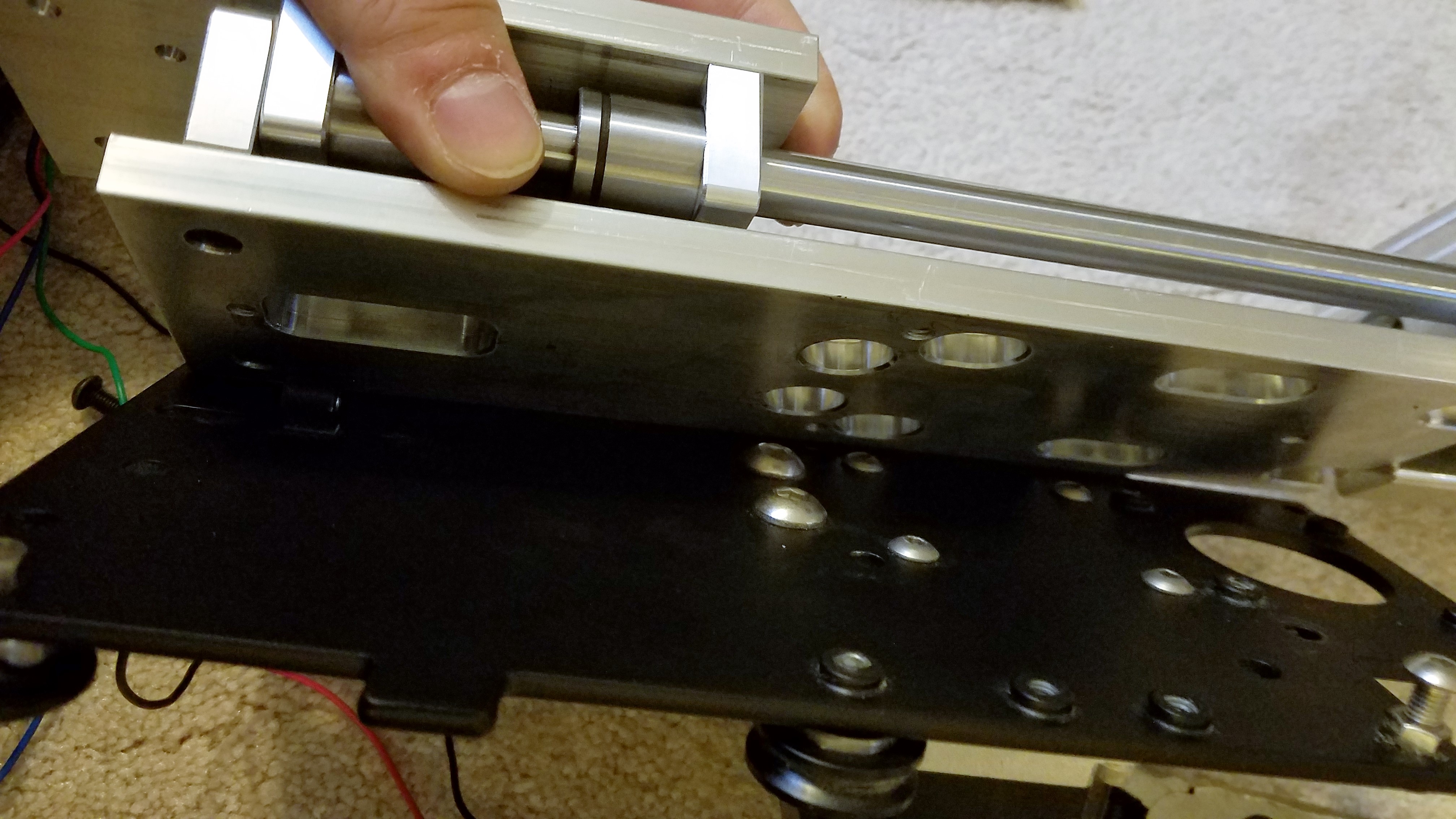
I took a week off work early to enjoy some assembly time for the upcoming holidays. Unfortunately, I ran into this problem over the week:
There’s some alignment issues with the gantry holes and the slider. The solution might be as simple as having to bore the holes larger (though I never tried drilling steel), but I contacted cnc4newbie in case there is another option/I’m doing something wrong.
Hey @Mcjjashik what’s keeping the plate from sliding slightly higher to align the holes? Is it hitting the reliefs for where the old Z axis stepper mounts, or the pulley tensioning nub, neither?
Dan
Hey Dan,
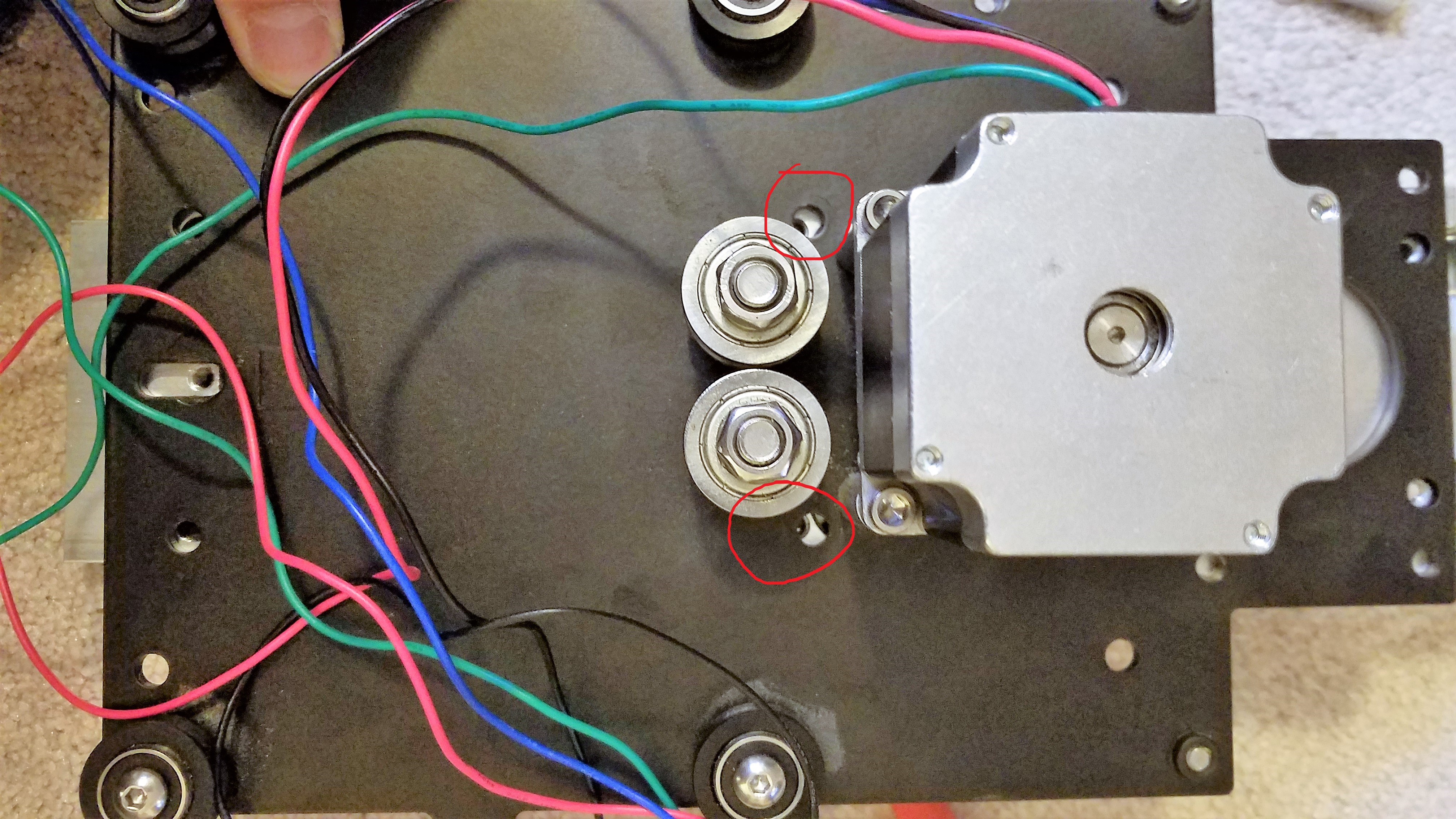
The pulley tensioning tub (surprisingly) is not the problem. It is hitting the reliefs for the screw heads on the X axis stepper mounts. Maybe this picture can help.
The pre-milled holes are so snug it does not move any further up.
Joe just responded back from cnc4newbie.
"Hi, we don’t know why but on some SO3 the holes on the carriage plate are not at the same place as the most other SO3, it’s why in the description of the product you can read "on some SO3 you will need to enlarge 2 holes
You can easily enlarge the 2 holes with a larger drill or using a dremel.
I’m glad I wasn’t going insane. Time to get out the drill ![]()
Hopefully you wont have to do any additional modding with yours when you get to tackle it in the future.
1 Like
Is that the X axis stepper mounts, or the X axis belt pulley bolts? Hard to tell from the picture, but it looks like the latter has a clash, no? I would personally go after the reliefs with a dremel or something rather than enlarging the holes due to possibly making the screws a loose fit and causing possible tilt of the spindle.
Can’t wait to try mine out, but unfortunately I still have many ornaments to cut/engrave, but I did a bunch last night, so I’m closer!
Dan
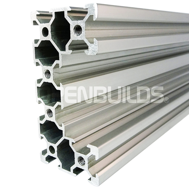
Jose, these rails only look strong. See the 1/16 thin web?
1 Like
Richard where I find it ?. I see 20mm.X20 mm. all rails in Openbuildings :
3 Likes
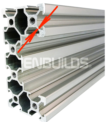
Ok thanks I learn ?. is the wall !.
Will not it be enough for the Z axis Richard? Or is more rigorous required?
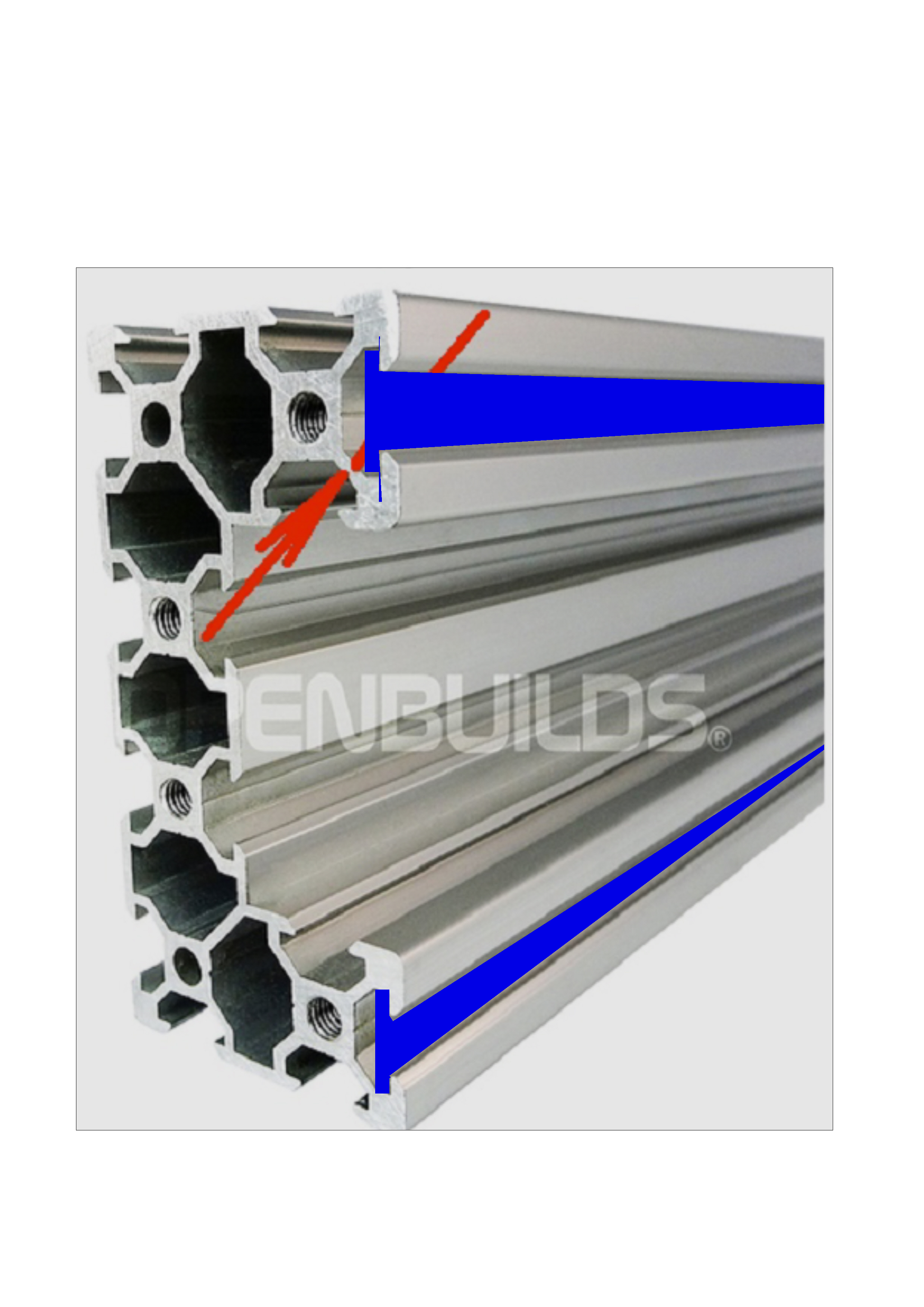
I believe that reinforcing this rail at this point would improve the structure to meet the needs of the Z axis, in addition the whole of the extrusion gives a good rigidity with the screwed stops. That’s what I think for people who want to use these aluminum structures. They are also only 25 centimeters or less!
Upon closer inspection, yes you are indeed correct that the X axis pulley bolts are the ones causing this problem.
I tried using a dremel with a fresh metal cutting disk but with little success. I stopped halfway since the cut was getting too messy (it wanted to cut more than it was necessary).
Instead, I found great success using a punch, then simply drilling a new hole exactly where it needed to be. I went from small to large using a vice, then sanding/filing to clean off the last few burs.
Hopefully you or someone else that runs into this problem finds this useful.
2 Likes
Soo… fast forward 2 months, have you found a fix to this problem using CM?
I was troubleshooting for about the past 2 hours both googling and changing my grbl settings one by one, with resetting them to “stock” Shapeoko 3 XL settings using grbl 1.1 / build 410, until I finally found (ironically) back to this thread on google. I was so excited when someone else was reporting the exact same issues I was seeing - only to find it was not yet resolved.
@WillAdams do you think you can help or provide any input?
I have tried the same things @xcaper has been using with changing $132, $20, $21, etc, and cannot get the z axis to pass 3.898" no matter what I do.