I’m afraid that I’ve never done anything like this particular upgrade — did get an Acme screw upgrade for my SO1 and did some other mods to it — my SO2 was dead stock (had to be to do the instructions) and I did write up some notes on my tweaks to my SO3 when doing my XL upgrade.
Please contact the folks who make this upgrade and see what they say?
That said, it’s a kit — take a drill / file to it? Fill in unwanted holes w/ a metal-impregnated epoxy such as JB Weld? Worst case is if you mess your plate up, you can contact support@carbide3d.com
For the software side, apparently some values are being hard-coded into the app — perhaps vertical motion is one of them? Might be you’ll have to use a 3rd party comm / control program.
I’m afraid that we simply don’t have the resources to support more than the stock kits and accessories.
Well, I have a bypass, would not call it a solution…
I really wanted to go back to CM. its so simple to use and I’m familiar with it and even considered going back to original Z design.
Then, for some reason UGS started ‘pulsing’ my rotor during a job, by switching off/on the SSR I use (and love!). This being a hobby, I don’t have much time to investigate what was causing this, it happened on two entirely different jobs. As a way to quickly find out if the post processor was causing this, I fired up CM and it ran both jobs without pulsing the SSR… So:
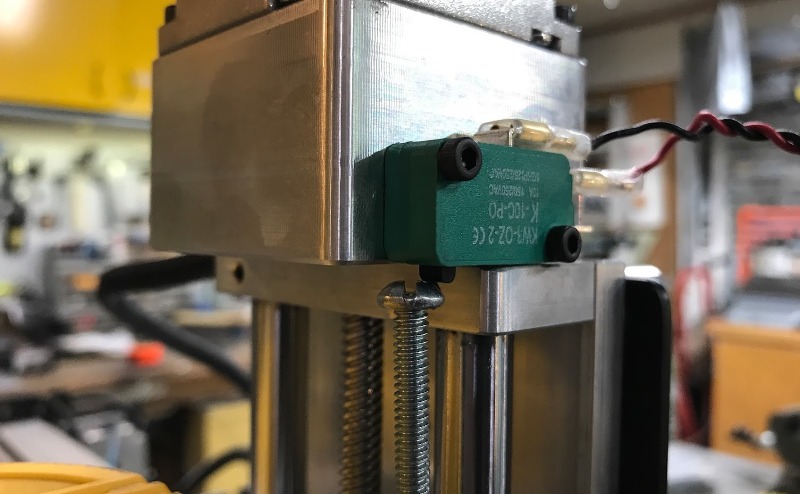
Knowing CM wont let me change the travel I decided to 'Fake" it into believing I had less travel than I do. I simply glued a small wood block to the top of the plate, such that my Z limit switch gets triggered about 1.5" sooner. This causes CM to think all is good and I can use the app with no problems.
I of course realize I don’t have the full range of travel anymore, but this was acceptable for my hobbyist use, and I can easily remove the ‘early trigger’ if needed.
Not ideal, but what the heck, works for me
Thanks for your input Will, I appreciate it! Yes, I have contacted the folks who have made this, and I had no problem after adjusting their product, after some modding, to fit with my Shapeoko 3 XL.
I was more focused on getting the software side correct using carbide motion. I think you are right, with vertical motion or some simila hard-coded in. UGS worked great, but I would rather use CM (especially with the recent improvements) than something universal.
If there are no resources, there is no problem at all. I completely understand the carbide motion team should focus on other improvements to integrate better with all their first-party products.
@xcaper that is a simple but brilliant idea. Thanks!
I am completely with you on appreciating the simplicity of CM. I will follow your footsteps and will add a small block since I have no current plans on cutting any higher stock any time soon.
Yep, the hard coded values in CM4 initially caused all sorts of problems with people crashing dust boots and such. It also makes it impossible to calibrate machine “center” as we were able to do in the past. I am really liking the current CM4 though in most ways and don’t really want to change over to something else. I bought my linear Z axis upgrade however specifically because it allowed more Z travel, so a block which limits Z back to hard coded values really does me no good. I’m not sure why these values have to be hard coded except that it makes it harder for the newb to mess things up by adjusting things they don’t understand, for the tinkerers it’s very limiting though. C3D has made leaps and bounds with their software in the year and a half that I’ve had my XXL, hopefully this will be fixed/changed in the future as well. Fingers crossed!
In the meantime I engineered a similar solution to the woodblock idea:
I drilled and tapped a hole on the corner of the aluminum plate underneath the limit switch on the z-axis to allow me to enter a screw to limit the z-axis travel when using carbide motion.
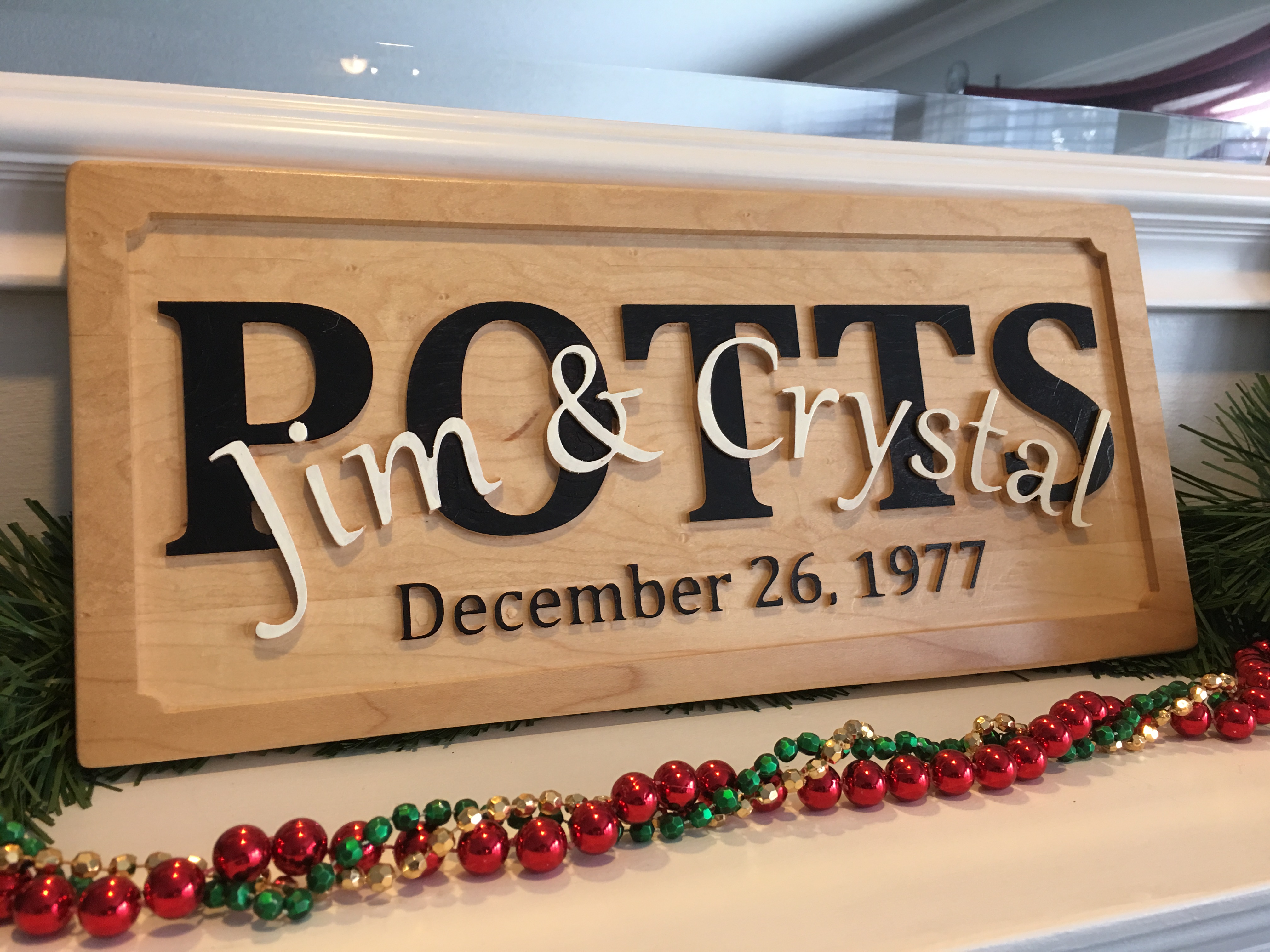
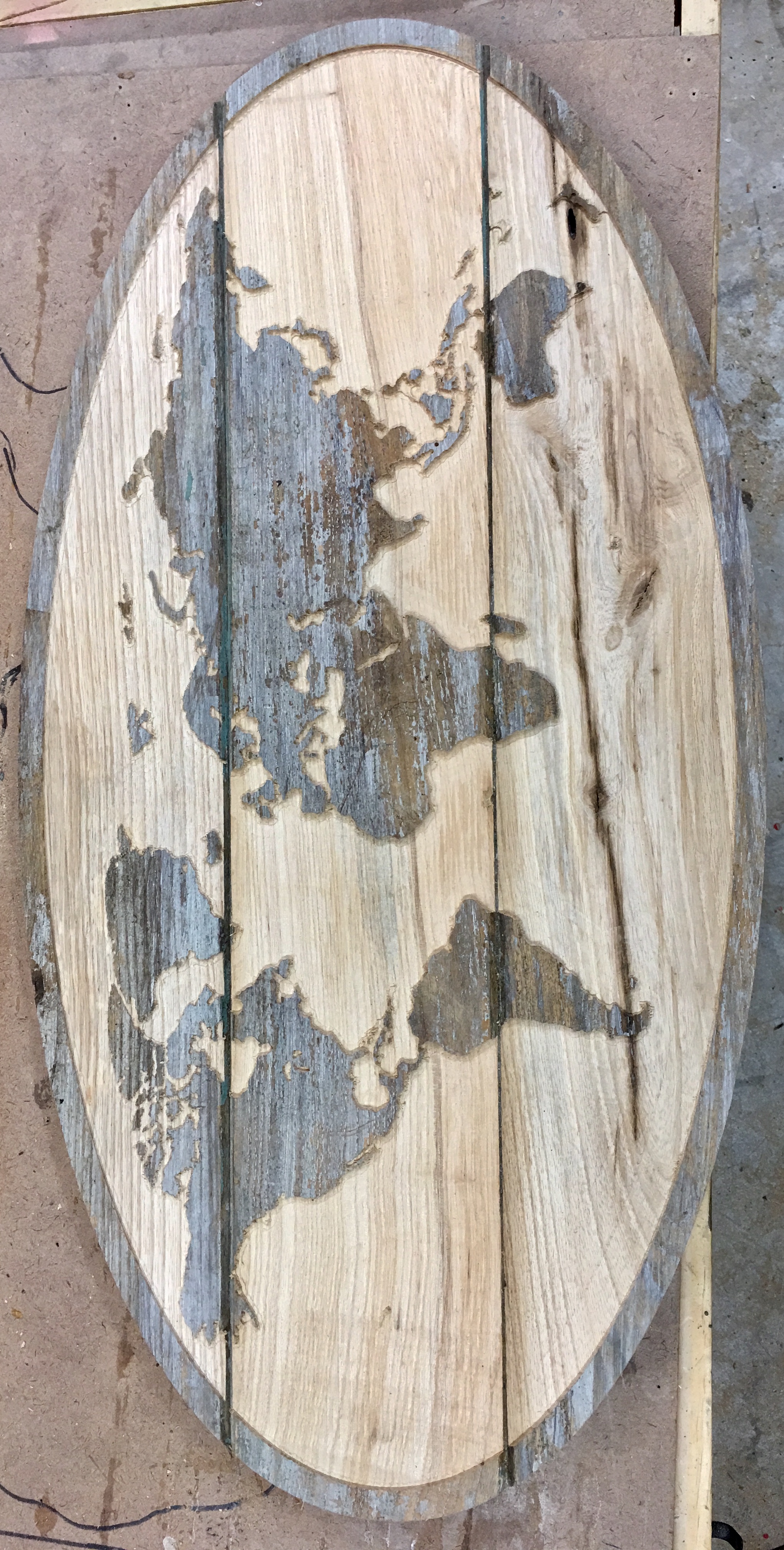
No downside for me. i have the older version of the SO3 that was upgraded to an XXL, so I did not have the issue with the tensioner being in the way. All holes lined up perfectly. I use UGS, so no problem getting the full depth available on the slider. It works well for me. I cut several projects for Christmas, so I will update with pictures when I can. But I’m getting good results. I have managed to lose Z position, but that was user error. I was using a short bit and managed to bottom out the Z travel, which caused me to lose steps. So I just need to remember to either drop my router down further in the base or raise my work surface when using short endmills.
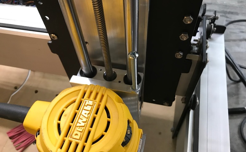
I just finished the install of one of these.
My notes:
On my machine, the two middle slider plate->SO3 carriage holes don’t match up. Joe told me to use just the top and bottom slots. I didn’t like this, so I opened up the holes in the carriage to allow the middle mount screws to be installed. Takes a bit more effort to plumb the slider properly.
I had to extend the relief around the heads of the bolts for the X carriage pulleys. Put a 1/4" square end mill into the router and do it by hand. >Don’t attempt to do this in a drill press<
There is now a spacer supplied for between the Z slider and the router mount. I found it not to be necessary with my router though. YMMV.
Having trouble getting more than 99mm of travel out of Z - just like everyone else. CM steadfastly refuses to use more than 99mm, even when $132 is set much higher (400mm, for example) I’ve got another 50mm available, and would like to mount the router higher in the mount to reduce the lever arm between the end mill and the bottom of the slider. Wish CM didn’t mess with this.
I was able to install everything without removing the carriage from the rail - all four of the mounting screws are accessible, and everything came off the carriage easy enough.
It’s configurable for 5" or 6" of travel, but I don’t see how you would actually set it up for 5". The screw holes for the slider at that setting end up underneath the router mount, which turns into either not being able to put the screws in the mount (linear rails are in the way), or you can’t put the slider back on the bearings, so you are stuck with a 6" setup. 5" would be stiffer.
I was not able to use the 725 acceleration on Z - this resulted in skipped steps for me. 450 working ok.
Hey all. So I got this upgrade, following all the instructions and the jogging while using CM is fine but when I run a job, like surfacing my waste board for example, the Z axis travels 10% down of what it should have gone. Not sure what the problem is… If I put the dial indicator under the spindle and go a thou at a time it shows perfect steps. But when loading the job it fails miserably.
Carbide Motion seems to ignore the $132 setting, so you need to use a different sender. Read through the post from others above. I have never used Carbide Motion, so this was never an issue for me. I use Universal GCode Sender and it uses the $132 setting I enter so I get the full travel.
I was going to say the same thing. I’m looking into a ball-screw based Z-axis, but first thing I did was test UGS and bCNC as alternate G-code senders because of the hard coded limitations of CM. I like bCNC better so far. I also though @Savant_PCs might have a post-processor issue. What post processor are you using for UGS?
I got UGS installed but not sure what I need to do to make it work. Any recommended spot for configuring the SO3 for UGS? I JUST now got it to connect successfully. I am using NIghtly 2
In UGS you go to the Commands tab, from there you can send the commands to set your max travel settings. You also need to adjust your steps/mm. I do not have my settings at the moment, but you will need to adjust yours to get the proper travel.
So I did this, can jog just fine but even in those programs I am getting the same problem… When I start the job, it moves to the starting position and its like it freezes on the way down, makes a noise but doesnt keep moving down and the program shows it saying it went to the correct Z height… I am about to take this thing off and send it back…