I have a new Shapeoko 3 XL w/Z-plus using Carbide Motion v5 (Build 513) on Mac. I copied the following symptoms from Stinkerton39’s 15 June 2020 post (I have the same issue):
New owner of the shapeoko 3D I am having difficulties with 3 error messages
homing failed, pull off didn’t clear
homing cycle failed
limit switch error (XYZ)
-All switches and XYZ connections seem to be in place after extended re-observation
-motors running hot during testing (added - and noisily moves an little over inch with noise left (X) and forward (Y) before stopping and giving the three errors)
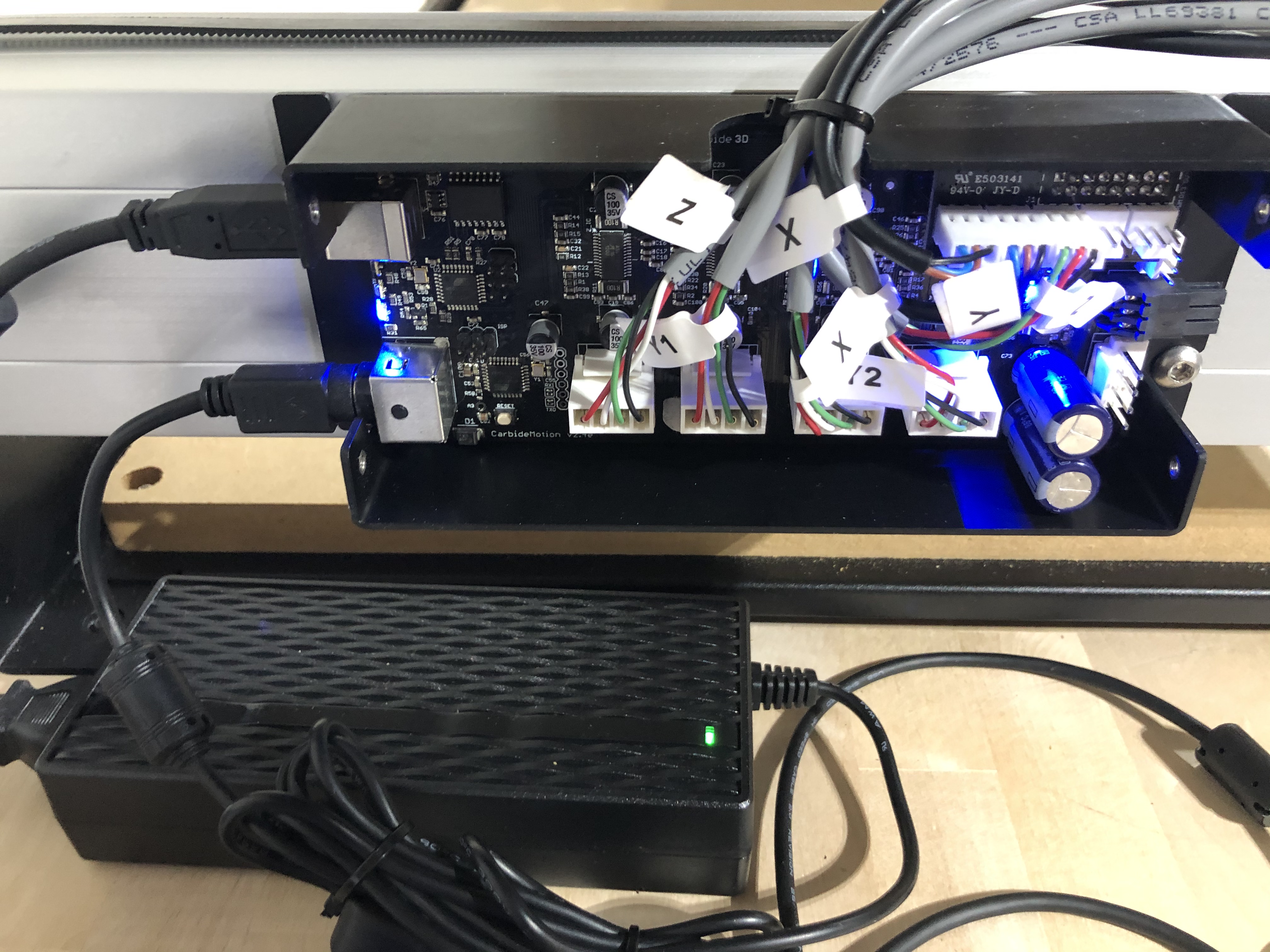
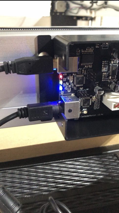
-red and green lights blink on the left side of the main circuit board.
So far, I ran through the recommended fixes in the forum:
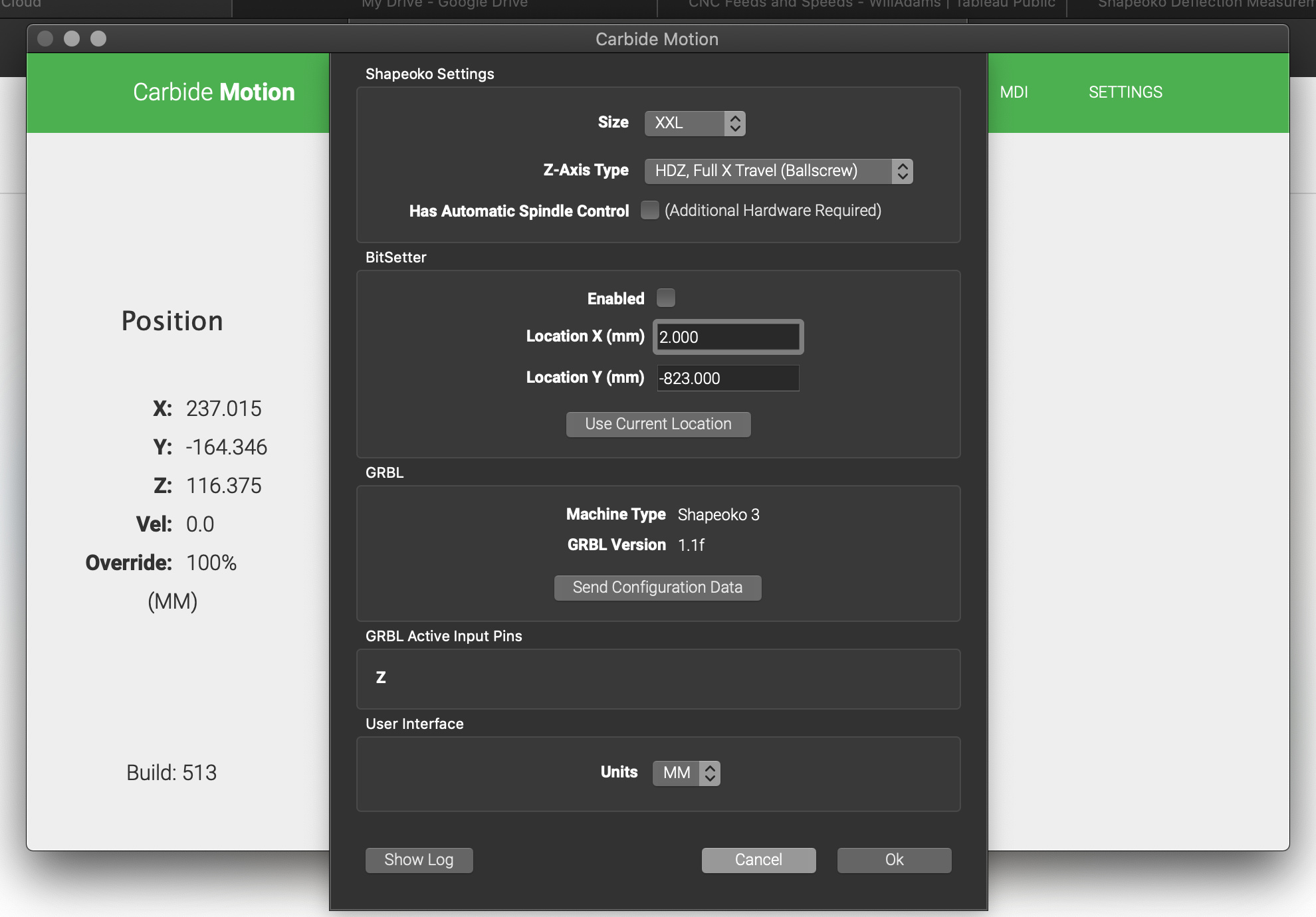
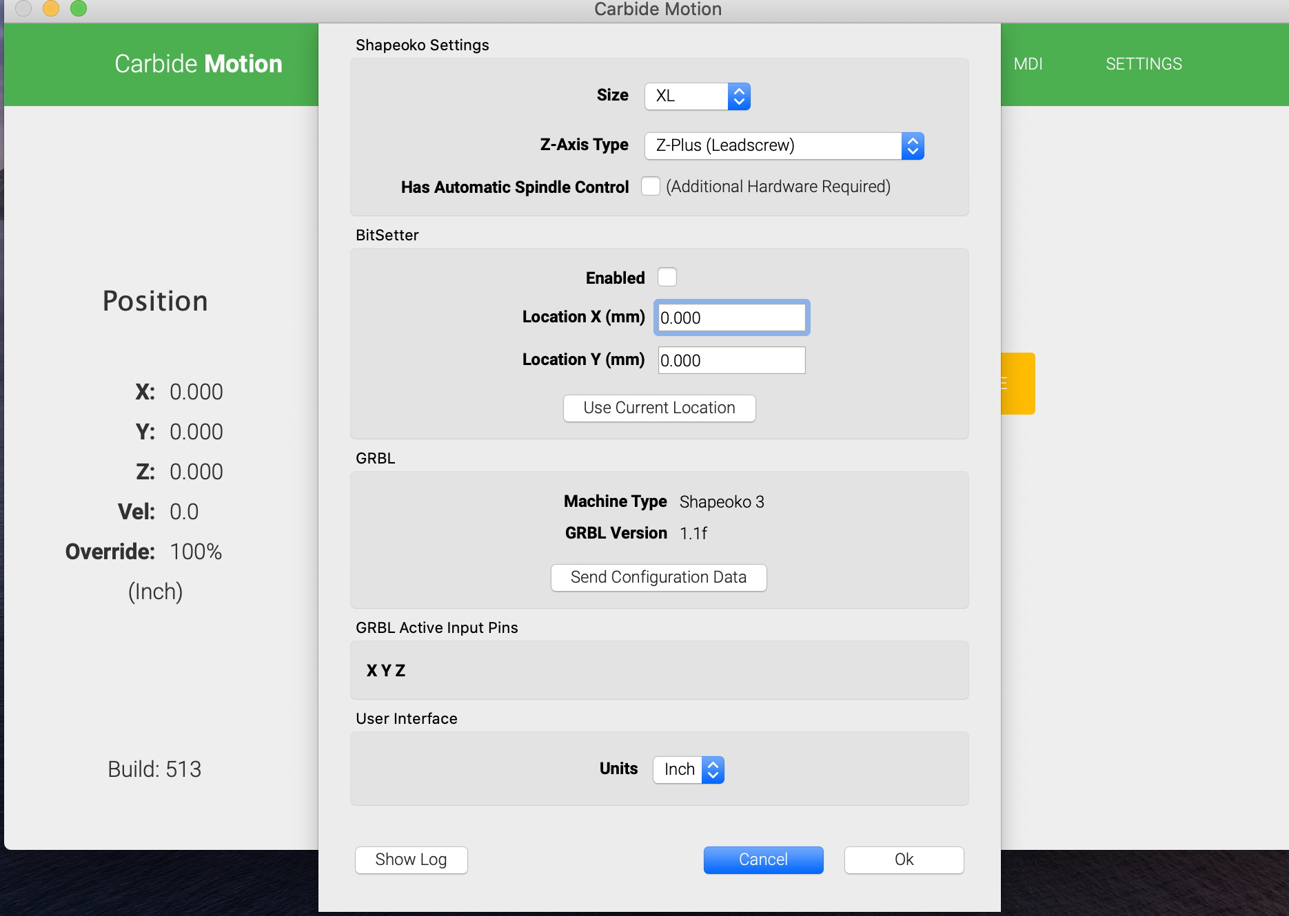
Confirmed I setup Carbide Motion v5 correctly (XL, inches)
V-nuts have been checked and are not too tight
Checked the belts - again, not too tight
When powered off, the gantry moves smoothly across the X- and Y- axes with minimal pressure
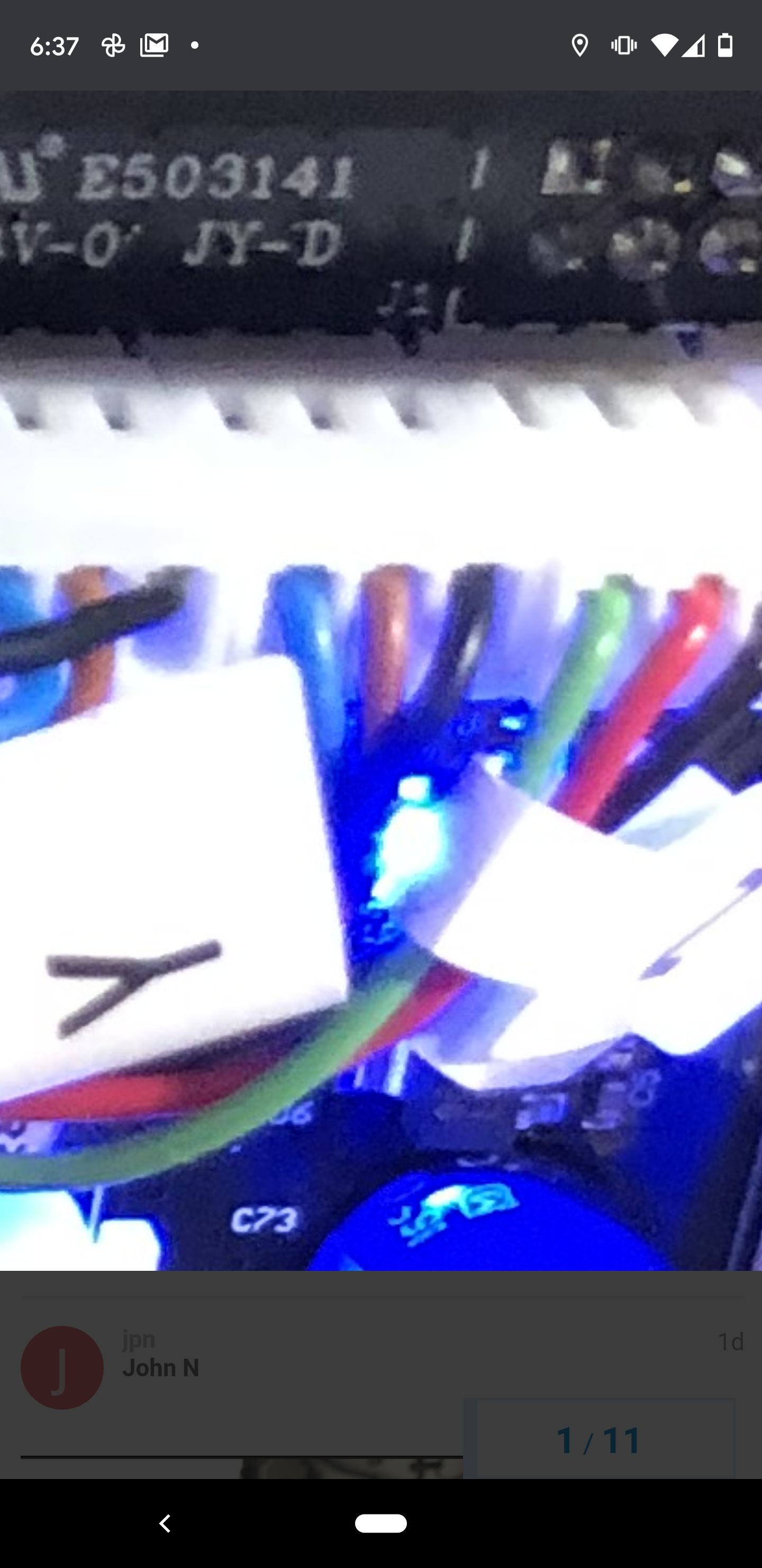
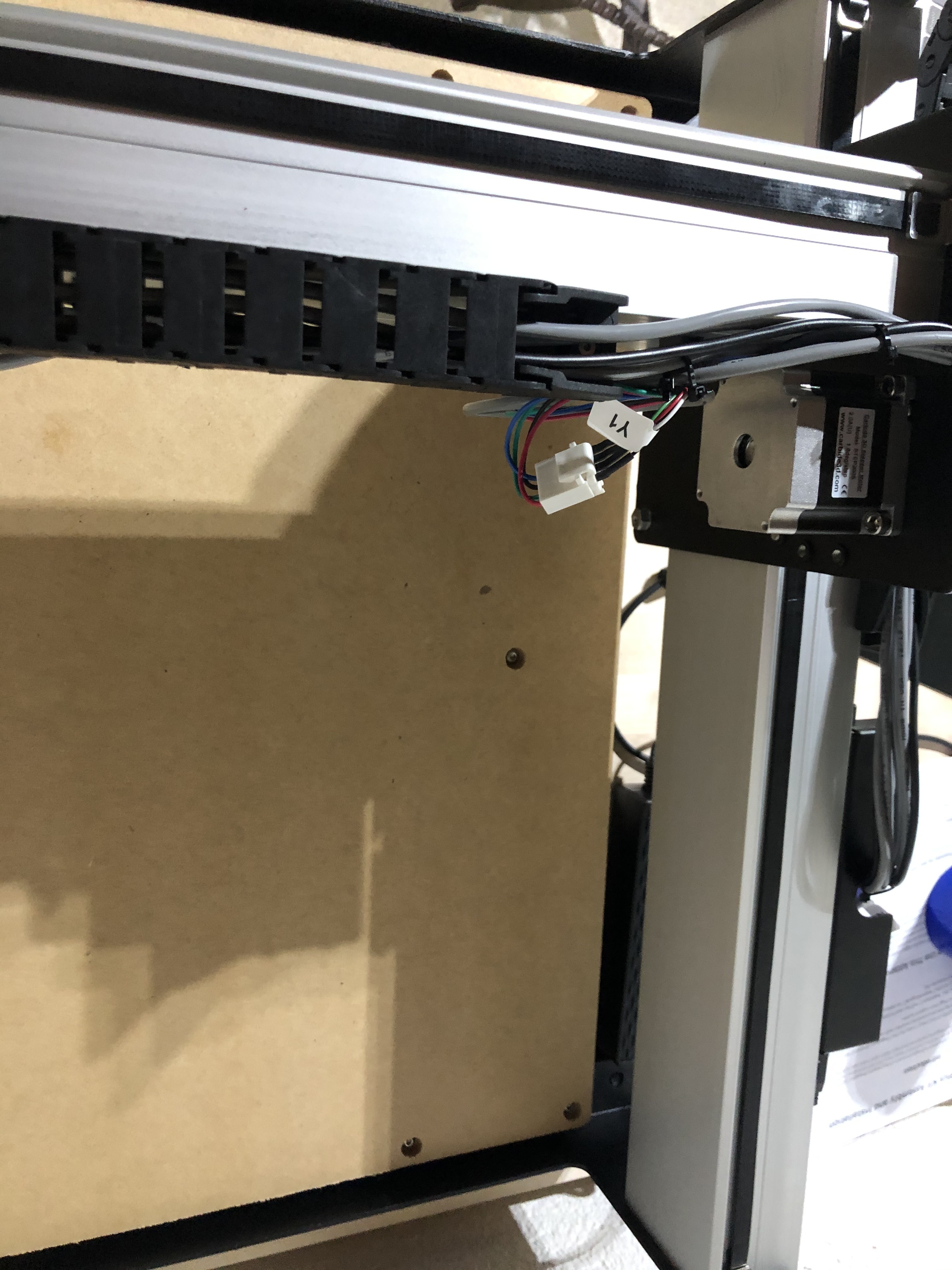
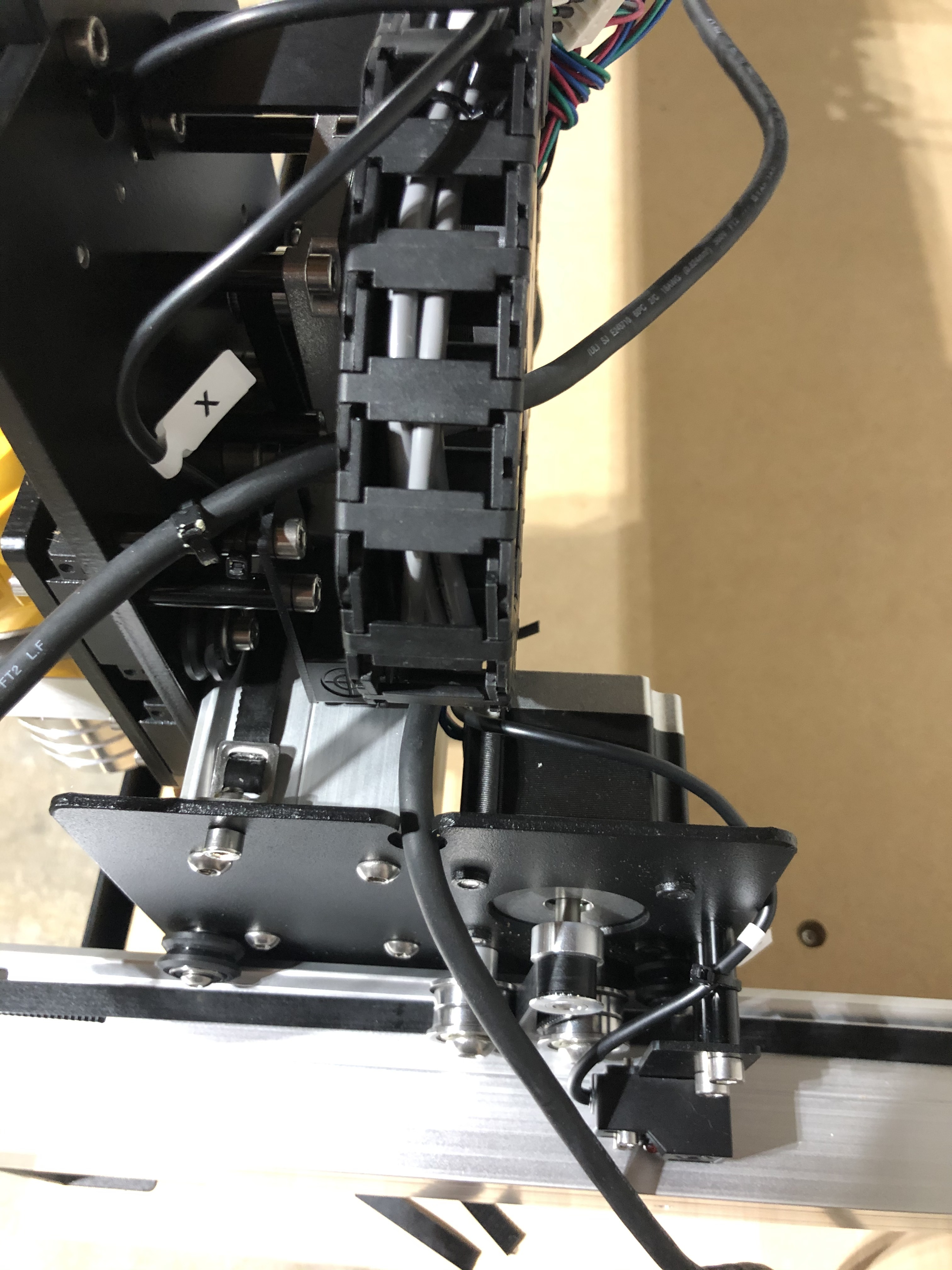
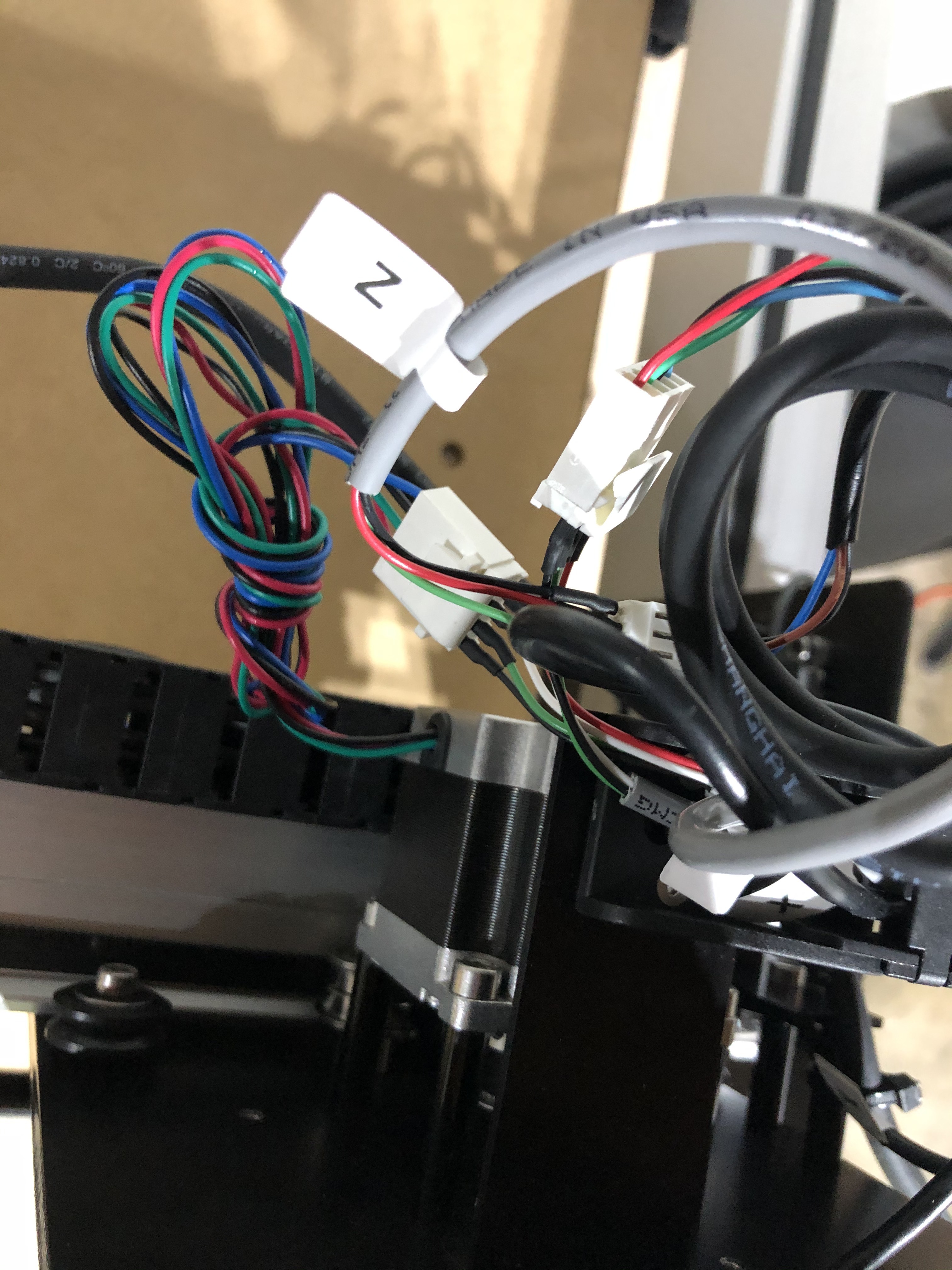
I have triple-checked the installation of the PCB connections - they’re correct as outlined in the directions and according to the stickers on the bundled wires
I reconfigured the software and still have the same error
Well Welcome to your new time sink!! :), sorry you are having issues but this is nothing to get agitated by, i am the welcome committee and your SO3 sign, bit like the BAT sign has gone up and others more technical will be here to help, suggest things to try, i assure you we will all help you get it fixed.
So see this as your first step into the wonderful world of CNCing and remember if this is your first time in CNC club you must break an end mill
If so you can see under “GRBL Active Input Pins” which home switches the controller thinks are “pressed”, although you probably have the proximity switches on your machine. If you can get here then you should be able to see if the home switches are acting properly or not, you can trigger them and see them appear here.
But in those pics from the other thread they appear to be black, brown, blue L->R so one of the two machines pictured is possibly wrong.
It might be worth calling support at this point and just asking them to look at a current spec machine and tell you which way round those wires are meant to be.
 and remember if this is your first time in CNC club you must break an end mill