New to CNC - Looking for Guidance

To begin, I am completely new to CNC, looking to kick off a project that, based on my initial runs, is a bit beyond my skill and knowledge.

I’ve been searching the community, though to be honest, I’m not quite sure what I should be searching for. I’ve also been reading through the official docs as well as watching a number of YouTube videos to soak up as much as I can (more of a visual learner).

Now I’m here looking for a bit of guidance.

What I Have

I have the Shapeoko 3; nothing extra, though I have plenty of bits. I am working with 6mm thick Delrin (from the Carbide3D shop) using a #112-Z 1/16th bit only (for this project).

What I’ve Done

To secure the Delrin, I created an elevated block inset to match the dimensions of the Delrin to hold it in place and ensure consistent placement each time. I’m using wax on the bottom of the block to keep the material in place as the goal here is cutting through the 6mm material and removing the cutout piece.

In the upper-left corner, I created a mini plug to consistently zero the starting point for the project to the exact height of the material and then back off ever-so-slightly to keep it just above the material.

I’ve also checked the belt tightness, confirmed the leveling, as well as the square.

What I Am Trying to Do

The goal is to make the exact same cuts on both sides of the Delrin–which I thought would only require flipping it over and restarting the exact same project (after zeroing back to the starting point).

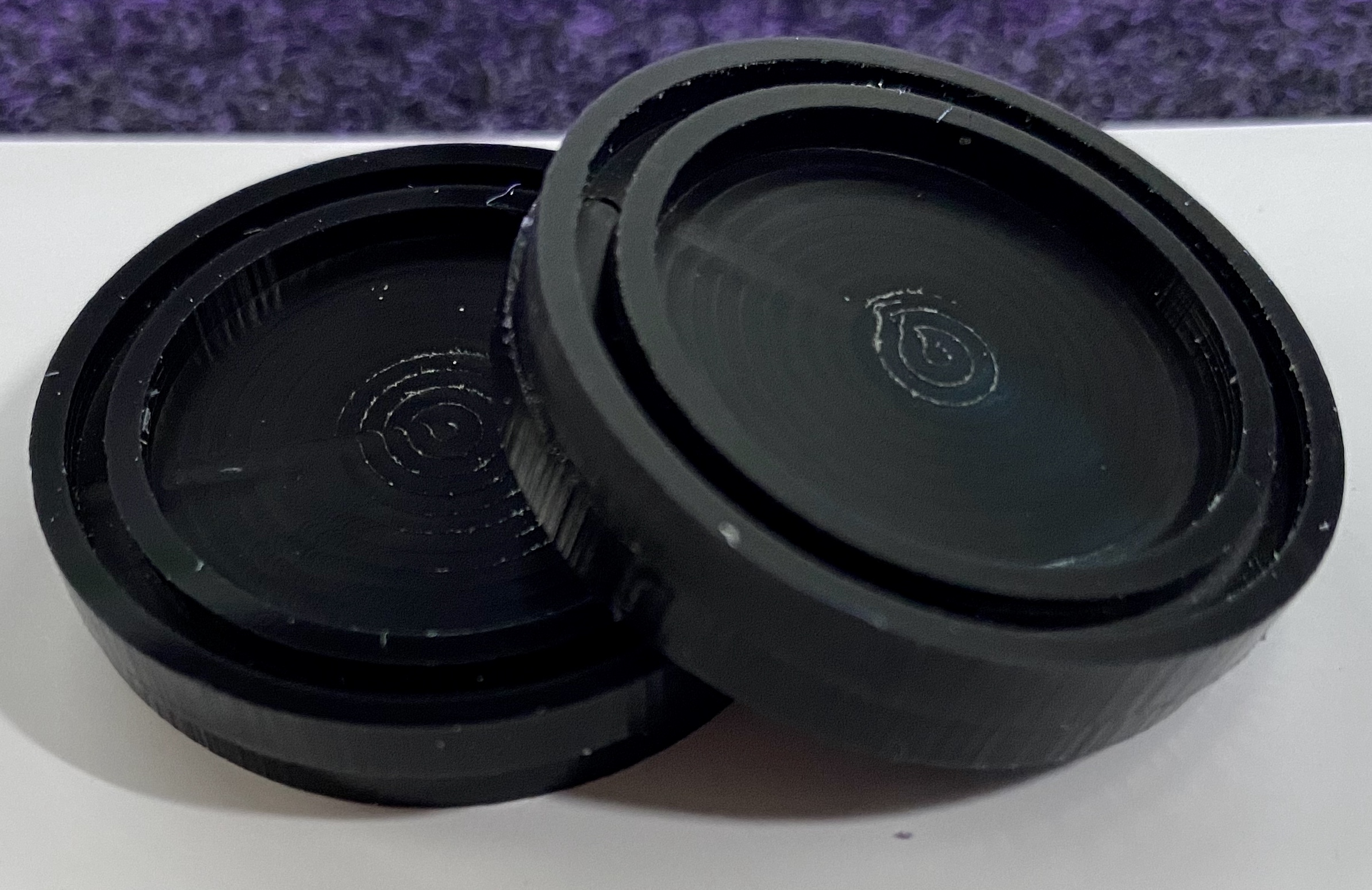
The project is pretty basic, to me. It’s a little smaller than a poker chip, consisting of:

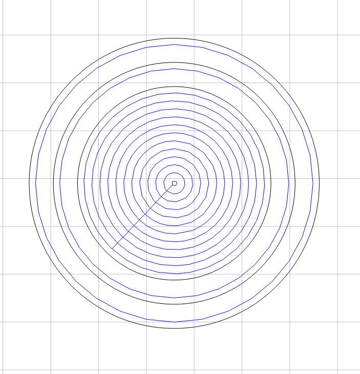
  1. One inner circle, which is set to a pocket so I can do an inlay; pocket is 1.755mm
  2. One outer circle (larger than #1), 1.755mm deep
  3. One final outer circle (larger than #2) which is the cutout, 3.00mm deep

I’ve used Carbide Create to create the circles and center them to the dimensions of the project, which is set to the size of the Delrin. I’ve then shifted the group up and backed off from the top so it’s set to be centered to the top-middle section of the Delrin.

My Issues / Questions

  1. Despite being centered in Carbide Create and the zero being identical by value in Carbide Motion, when flipping the Delrin and starting the project up again, the cuts do not line up. The last test was off by around ~12,7mm, resulting in cutting through the center pocket on the other side.

  2. My current process to re-zero to the project is to run the project, exit the Carbide Motion app, start the Carbide Motion app again, initialize, jog => rapid to current X Y (which seems to work). Is there a better way to consistently start at exactly the same position? Looking over the G Code, it seems G92 is not supported, so while I can set the zero using “G0X-284.5Y-39Z-77.510” in the .nc file, that does not keep a zero and the mill rapidly shot into the right side.

What the Project Looks Like

I realize I may be missing some details. If there’s more information I can provide, please let me know.

Any and all help is most appreciated!

Which axis are you flipping on?

Where are you setting the origin?

Could you post the file and step-by-step notes on how you are securing your stock and setting origin relative to it?

1 Like

What do you mean by this? That command will move TO X-284.5 Y-39 Z-77.510 as compared from your work zero.

@WillAdams

I am flipping the material on the X axis, much like flipping the page of a book.

For the steps to set the origin, for a new project run:

  1. Start Carbide Motion; initialize
  2. Jog => Set Zero => Zero All (mill location = top right corner of the Shapeoko)
  3. Fast Jog to the top-left corner of the Delrin (X = -288.125, Y -40.625)
  4. Drop Z to the top of the plug
  5. Set Zero => Zero All

Once the first side is milled out successfully:

  1. Close and Start Carbide Motion, initialize
  2. Jog => Rapid Position => Rapid to X Y
  3. Zero in Z
  4. Set Zero => Zero All

Run the second iteration, which is using the same .nc file as the first pass.

This is likely not the best way to do this. I am completely open to recommendations. It has, however, been the only way I’ve currently found to reposition back to the start of the project without having to manually jog.

GCode Attached below

c3d-gcode.nc (129.1 KB)

@neilferreri

Honestly, I was simply looking for a way to directly modify the .nc file so I could avoid manually setting the start and zero.

The goal is having a consistent start and zero so all I have to do is load the gcode and hit run.

Are the measurements of the Delrin block accurate?

Have you considered using the center?

1 Like

are you using a right angle jig on your spoilboard to register the bottom left corner of the piece and make sure that it’s squared up?

The piece is perfectly squared, yes?

1 Like

After you’ve flipped, you are no longer using the same corner for XY zero. That’s why the questions above about whether your part is perfectly square.

There’s a few steps in your procedure that aren’t really necessary, like closing and restarting.

1 Like

@WillAdams

Initially, they were not as Carbide’s site noted the 6mm being 4x6, when it’s actually 4x5". I converted this to mm, giving X = 127.00, Y 101.600, which is accurate based on measuring the material.

The goal here would be to print 6 of these pieces per piece of material–3x across the upper-top and 3x along the lower-bottom. I used the upper-left corner as I thought that would be the easiest approach.

Open to ideas on how this could be done better though.

@GJM

I used a level to check the square, top to bottom and left to right. I also broke out a straight-edge, long enough to check the positioning of the blocks and plates in place to hold the Delrin.

The steel plates on the base are squared, as perfect as could be without cutting them with a laser. The Delrin is aligned to two of those edges to keep the alignment as consistent as can be.


Gave the project another run. I don’t know what is different, the the gap is smaller than the initial, but I can’t seem to get it dead on. In the picture, you can see the lip on the top right (the bottom left has the same issue).

Any deviation in measurement/placement will result in this sort of difference — my suggestion would be to cut this as a one-sided project w/ a tool change to a #102 to cut the perimeter, leaving a roughing clearance and then taking a full depth finishing pass.

Even if you have do to do it as a two-sided piece cut the entire perimeter as a single setup.

If you have to do it two-sided, consider making a fixture to ensure precise placement of the stock — put down a block of MDF can cut a pocket in it the size of the plastic — if the pocket turns out a bit oversize position consistently:

  • first side push the block to the top left
  • second side push the block to the top right
1 Like

That can be done but if you want to do it that way, the first step is to ensure that the size of your stock is as precise as the cuts you want to make.

If you assume your stock is 127mm (so place the center of your cut at 63.5mm from the left of the stock) but the stock is actually 130mm, the cuts on either size are going to be 3mm apart from each other.

To eliminate this as a problem, machine your stock to size, then it’ll be as precise as you need it to be. Just find the length of the stock as measured with calipers or a tape measure or something and then mill off 2mm or so from each edge.

Next, you need to sort out the zero. It’s important that the zero you set results in the middle cut of your code being precisely in the middle of the stock. Any deviation and your cuts won’t line up.

I would recommend that rather than set the zero at the top left corner of the stock (which makes you reliant on precise stock dimensions and G-Code offsets), you set the zero at the very center of the stock. Zero by touching off the left and right edges of the stock and calculating the midpoint. Same with the top and bottom edges.

2 Likes

@WillAdams

For this project, dual-sided is required as both sides have inlays that are press-fit into the center cut.

What I’ve rigged up so far is pressure-fit, where a shim is inserted along the left side to press the stock tightly against the side. There’s zero movement with the shim in place and I’ve tried to move the stock while the router is running during a few tests; it doesn’t budge.

Cutting in a single pass is doable, though the inner cuts are also off so I’m still scratching my head on the alignment piece.

From what I can see, Carbide Create doesn’t have measurements on the grid, or allow you to define the spacing from the edge of the stock to ensure a consistent offset. It seems movement is either by arrow key alignment to the next snapping point, or reduced when holding down shift and using the arrow key.

Is there a way to be more specific so spacing is exact?

In the design tab, what I’ve been doing is aligning a single puck to the top left and top right so it’s touching the borders, selecting all, then arrow key down and right so it’s offset.

Jonathan, if you need something centered that is round, start with the XY at the center. You’ll have to create another fixture location that is round (like @WillAdams said above) to hold the obverse side, but that can be created at the same time as your present square fixture location. The two location’s center will be a simple X or Y offset away from each other. Appropriate toolpaths can be generated for production efficiency.

Seems as though registration pins might be in order? Lay them out symmetrically in CC and cut the holes directly in to the holding jig and the material in the first two passes…then flip and register?

Wouldn’t that be the most repeatable process?

1 Like

If you want a consistent spacing on the stock drawing a series of nested rectangles, with extras at corners if need be to set spacing would be one way to do this.

@WillAdams

I decided to start from scratch, validating leveling, positioning, and potential for movement along both the X and Y axis. I created a new wooden fixture that is just short of the width of the Delrin sold by Carbide so it has an extremely tight fit with zero movement.

To ensure that the material is held in place tightly, I’d drilled pocket holes on the four corners and inserted heavy-duty screws that clamp down on the material.

As recommended above, I ran another test, zeroing to the center of the material. When flipping, however, the cut remained off-center and ended up destroying the puck.

It seems that despite absolute center placement in Carbide Create, and the zero being identical, there’s a variation somewhere and this is what doesn’t make sense to me. All things equal, if the material does not move left to right or right to left, if the zero is the same, and if the design isn’t touched, should it not mill in the same area?

I’m open to creating a pocket for a single puck and running one-sided and cutting through on the first run, though from an efficiency standpoint, that becomes time-consuming.

Also, realizing I am new to this, so I have a lot to learn. I greatly appreciate all the feedback and everyone’s willingness to help me work through this :).

One issue is aligning on center doubles any error — usually this can be minimized by pushing to one side, then the other after flipping.

How large is the error/offset ?
One suggestion I have not seen above is to NOT re-home the machine between the two sides (you seem to indicate in earlier posts that you intentionnally quit Carbide Motion, relaunch it, and re-initialize (which re-homes the machine). It would only explain a very small offset though.

2 Likes

Would you mind posting the C2D file? I see the .nc, but not the design.

1 Like

@GJM Attached below, thank you in advance for taking a look!

project-puck.c2d (16.2 KB)


@WillAdams The current block is stationary, held in place on all four sides and can’t be moved. I took this approach specifically to limit the potential of introducing an offset when flipping the material.

@Julien I’ve ran tests using re-homing and then simply keeping Carbide Motion active and using the “Rapid to Current X Y”; both result in the same issue.

The offset is significant enough where if you look at the project C2D above, the “Outline - Top - Left” path cuts into itself when flipping the project over.


I did measure the center point of the material when placing and securing it. The center point is at 2.5" on the X axis (being a 5" long piece of material), with the center point on the Y axis being 2" (being 4" tall).

My marking was dead center and the bit was centered to the overlap.

Sorry if you’ve already said and I missed it but, have you measured the parts you’ve cut to check whether the machine agrees with you on how large a mm is? Are the pucks the correct diameter (ignoring the offset)?