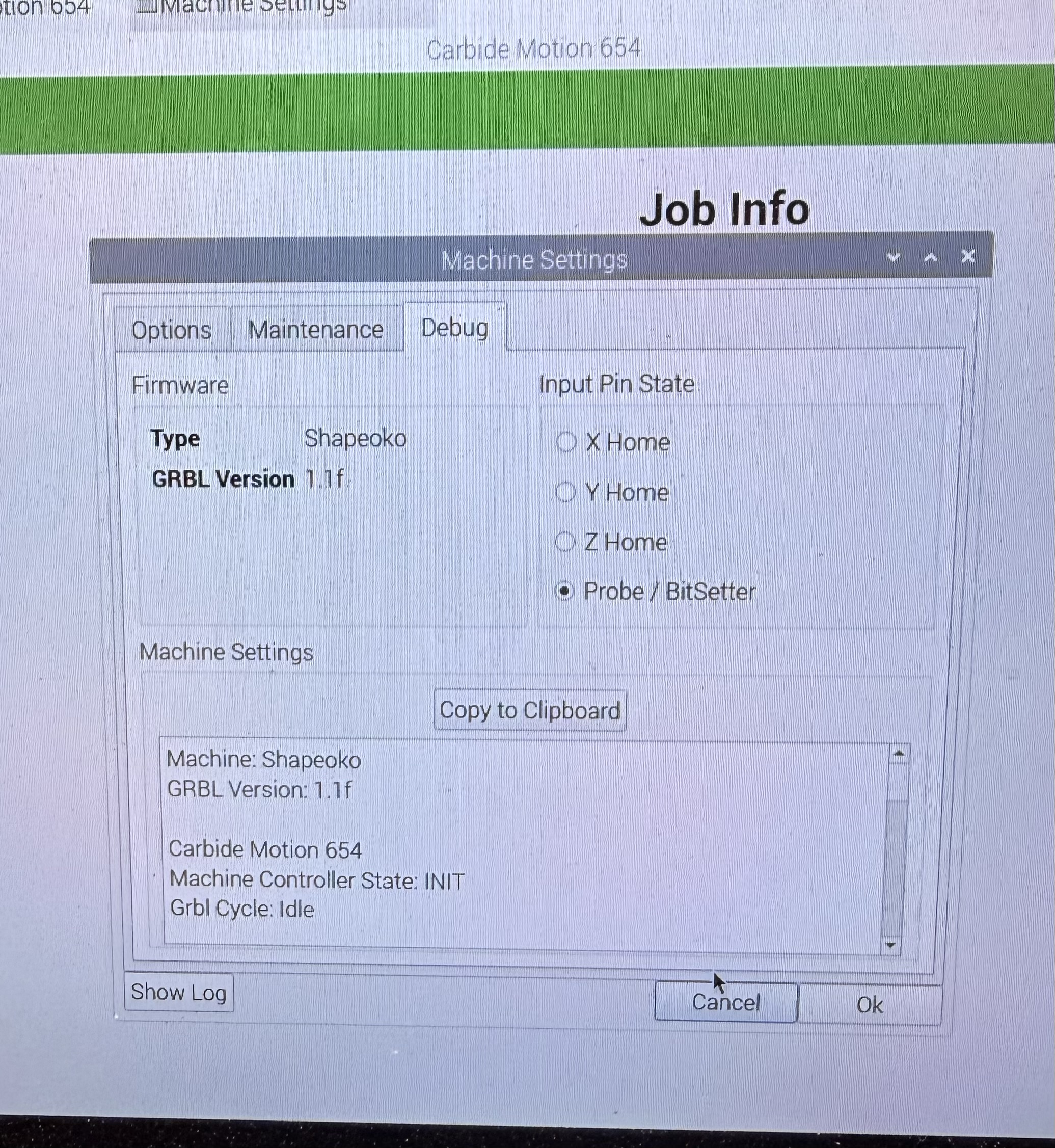
Picked up a used 4 XL. My first foray into CNC. (Brother-in-law has the same model.)
When I push the plunger of the BitSetter there is no indication of its connection. I’m guessing 99.9% of the time it is the sensor and not the logic board. But … how to check sensor output and logic board input. There’s 3 wires. Is it as simple (and is it safe) to just jumper any two specific wires (and which two) to verify which component might be in question?
That will give me the general function, but the goal is to be certain that a lamp failure reflects a sensor failure and not a logic board failure. (I’m an IT guy, so debugging hardware is always a step-by-step process. I don’t want to buy a sensor if it’s the logic board, and vice-versa.)
You might want to run through the machine setup and make sure the bitsetter is selected. Power on the machine, do not initialize, go to setup at the bottom of the screen and go through the steps. It only takes a few minutes to complete.
And … replaced. Both the plunger (b/c it had some serious tool marks and I thought while I’m in there…) and the sensor.
Now …
On the logic board, the Y lamp is always on.
X and Z respond to metal in their vicinity
Which gets back to my initial question … I wanted to figure out a way to tell if the problem was the logic board or the sensor. “Replace the sensor” sounded like something an auto repair shop would suggest. Keep replacing parts until you find the problem.
Also, I never see turned on the indicator lamp on the BitSetter by the plunger. Not when I push it down. Never on.
Any logic board diagnostic procedures/schematics out there? I have a scope and all the meters I need.
So … Here’s the results. It wasn’t the controller board or the sensor. It was the extension cable. Even though I’d done a continuity check on it. that wasn’t enough. There was apparently a weak pin in one end. Worked when pushed together for the meter but not when I wasn’t testing. That was the only thing left.
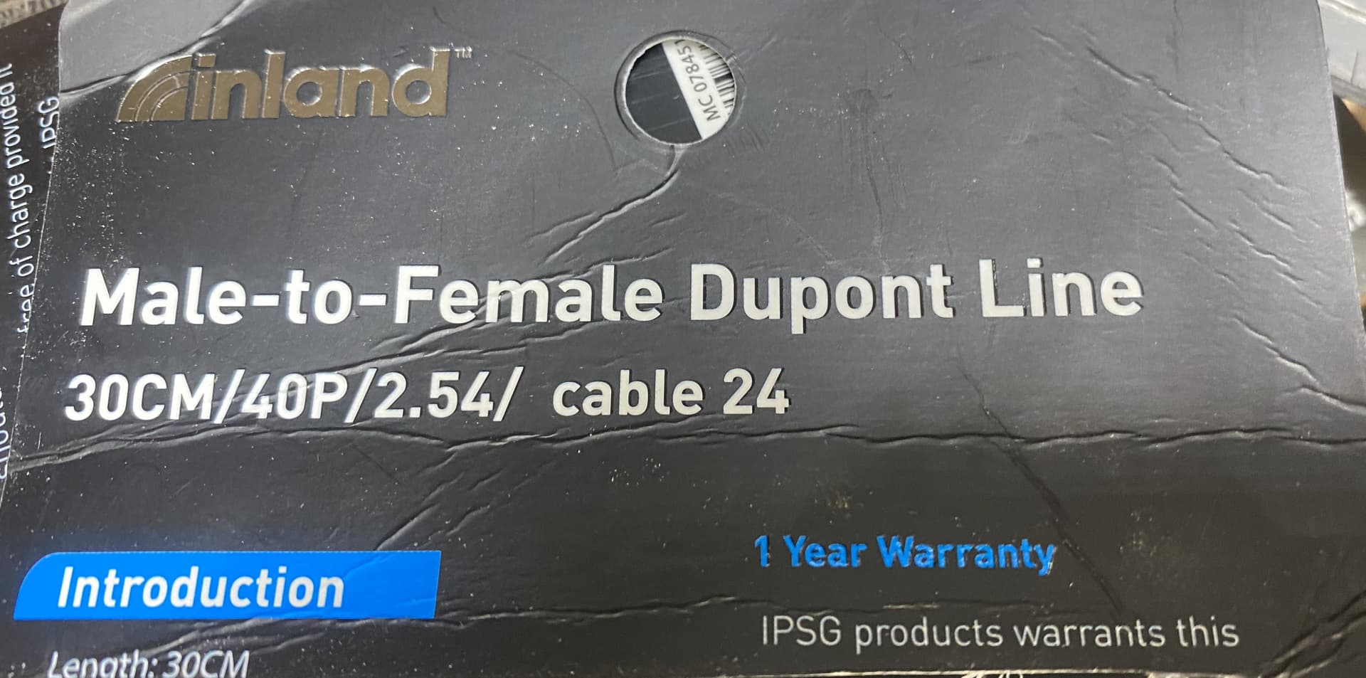
Found a 30cm ribbon cable at the local MicroCenter. Separated 2 lengths of 3 strands and plugged them in. Works perfectly. Just add a little tape to hold until I can get the proper cable.