I saw a few posts about upgrading the Z axis and though it might be a cool upgrade.
I have a large spindle that strains the springs a fair amount and when milling aluminium my Z belt frequently gets clogged with chips, jams then screws up what I’m working on so there is value in the modification.
I liked the look of the CNC newbie kit, but
It’s in Canada and I’m not
It sticks to the standard X axis plate, which whilst in my eyes is a little lazy
It also isn’t compatible with my spindle, and doesn’t include access to adjust the spindle when not sitting straight.
It either has too little or too much travel making it too large for my enclosure
I also feel the X axis can be tightened up a little bit.
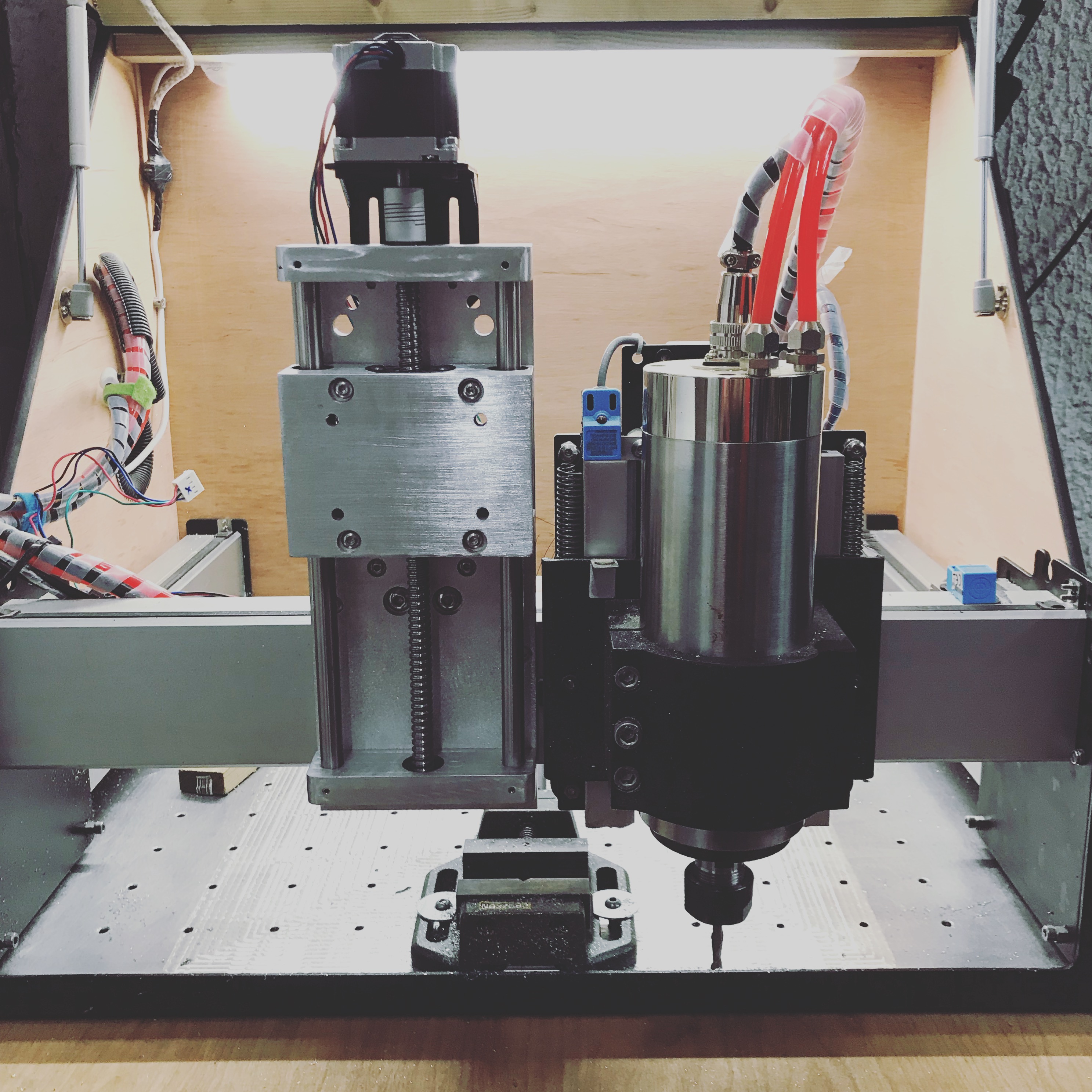
Anyway, drum roll… we’re a community of makers, so I made my own
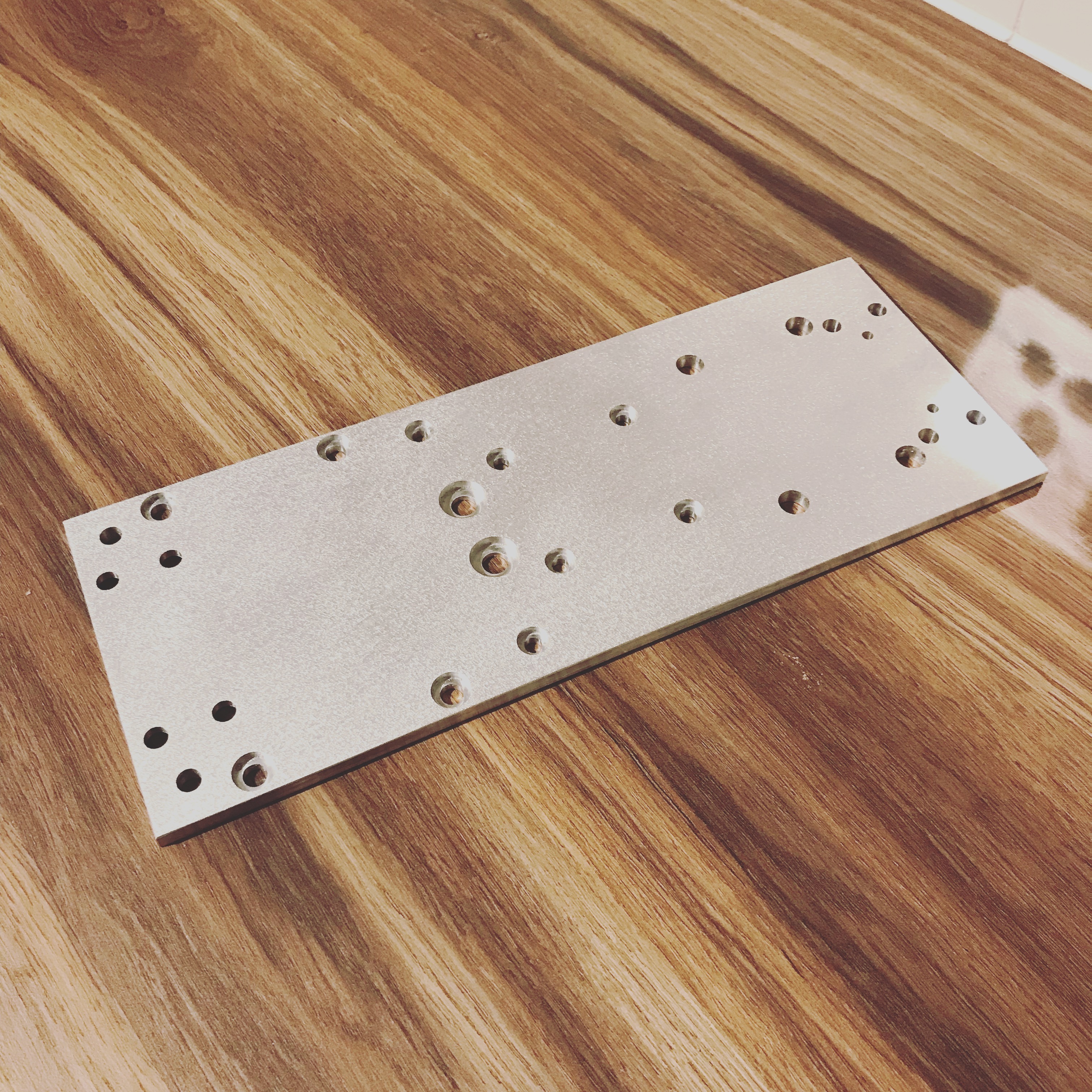
It involved a custom made ball screw which took a little longer to establish which is what delayed this. Milling 20mm aluminium bar, large sheet, probing, dual sided milling, precision drilling with a shapeoko, learning new ways to mount things. Everything was made on the Shapeoko 3 and cost less then £100.
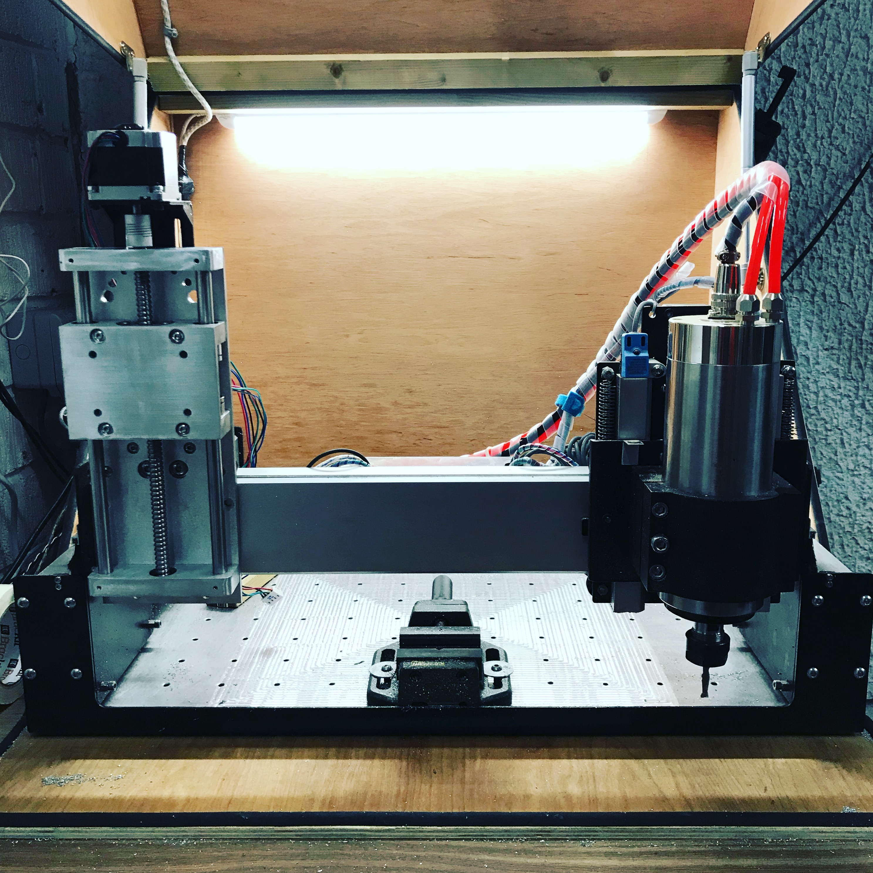
I’m hoping to install it tonight - but its all tested and does fit as expected. Due to it’s narrowness it also has more X travel.
Videos, files and write up to come.
@WillAdams any idea what the travel settings would be for a 1204 ball screw?
Hey Luke, this looks really good, and now I’m feeling a bit lazy with my CNC4Newbie slider (which I’ve also been too lazy to install). I have a question if you don’t mind (maybe you answered in the video, but I’m at work and have no audio, shhhh!). Since you did away with the X plate, did you attach the V wheels any differently? Second question, if the V wheels are in the same arrangement, does the narrower stance, plus your heavier spindle make the loads on the V wheels worse? I haven’t installed my new Z, partly because my machine I working well, partly because I had a slew of Christmas stuff to cut, and partly because I’m just lazy. I do really like that you’ve been able to move the router centerline closer to the X rail, that s a definite bonus.
Those are come good questions as these were actually a concern of mine too.
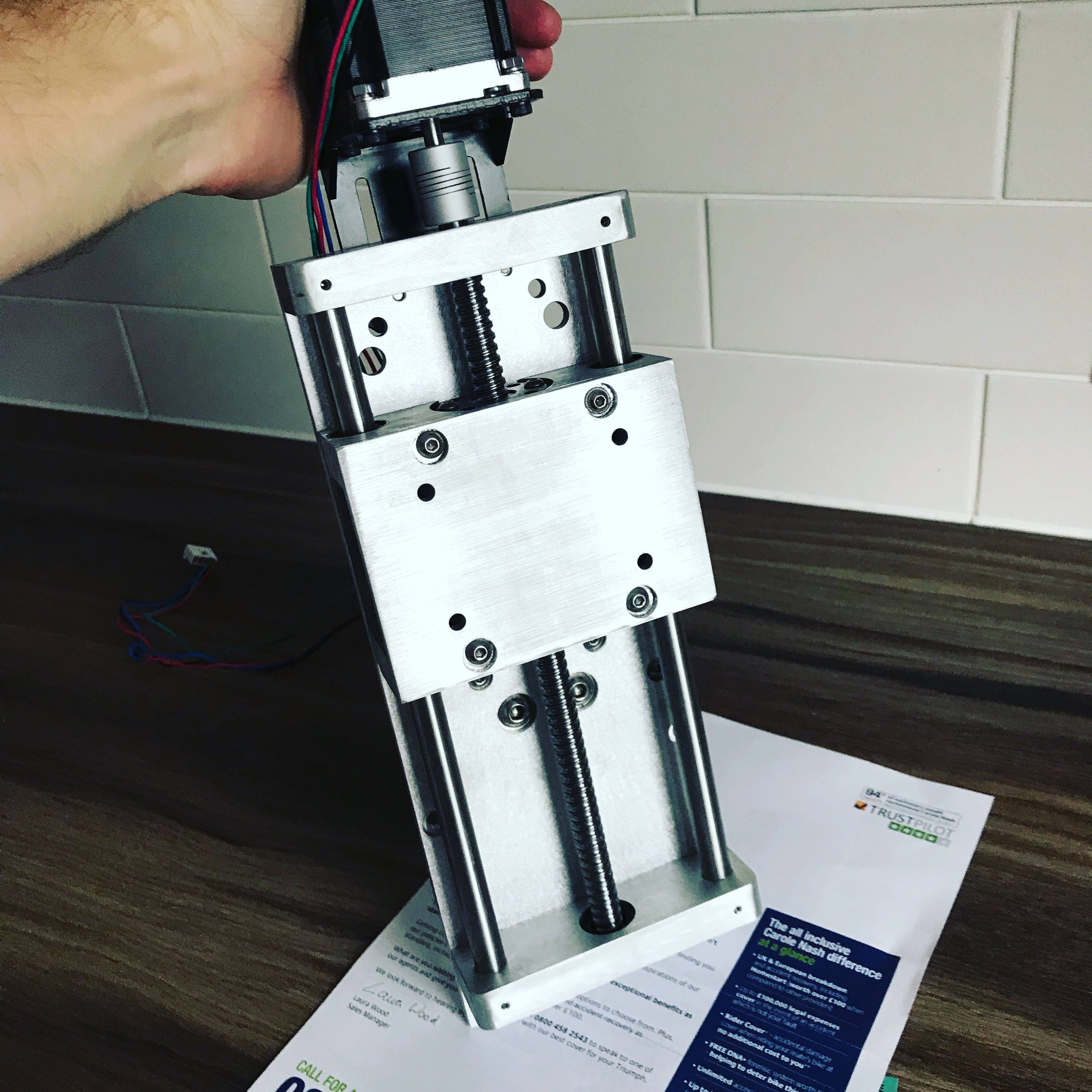
The X axis V wheels are actually in a slightly different arrangement - they are obviously closer together left-right to which allows for a slimmer Z axis. I was worried that doing so would change the forces applied to the carriage and increase the pressure on the V wheels. At present (bear in mind I’ve only moved it around and done some really quick passes on aluminium) I’ve not had an issue yet, but it’s early days. The Z axis seems really smooth, maybe even smoother than before and I think thats because I made another change to the layout.
I also changed the vertical spacing of the V wheels, I believe as standard there is a 107mm gap, I shorted this to 106mm which is a tighter tolerance. There would be the possibility to over tighten, thus far it’s just right, but I can tighten more if needed, where as when using the stock plate I could rotate a eccentric nut 360 (all be it with resistance).
I should also mention I have never cracked a v wheel to date - and thats with a 2.2kw spindle mainly milling aluminium and I have crashed it too many times to count (usually because my Z axis jams and I hit the stock).
The biggest downside is I don’t think I can use Carbide motion any more due to the soft limits built into the software - but I am running UGCS with success and it has some nice features.
Yea, that’s part of why I haven’t added my new slider as well. I’ve played around with UGS. but have not run a part with it yet. Glad to hear someone else is in the same boat. Wish they would put that functionality back into CM4 like they had in CM3, but I’m not holding my breath!
I say “Gerbil” too (had a couple as pets when I was a kid) — Sonny (@chamnit has noted that there are a number of different pronunciations, and that he is amused by that).
Very nice work Luke! I may be needing to replicate something like this… the slowwwww droop in Z over the course of a long job on the stock carriage is starting to get irritating.