New user questions

thanks, man, I hope they’re paying you well.

when I zoom in or out, the grid moves sideways? how to put the grid where I want it?

the overall shape will be a spiral, since xylophone bars are of different lengths. I suspect the curve tool will do it?

The Curve tool will allow you to describe/draw a spiral, but it will not allow placing geometry along the spiral.

Please sketch out what you are trying to achieve, label it w/ dimensions, then post a .c2d file showing how far you’ve gotten and we will do our best to walk through this w/ you.

Thanks, It will take me a few days to get it all dimensioned. I still have to find out if your program is compatible with the CNC machine at school. UCF, Orlando Fla

I’m also looking for software to design flutes on the lathe. Holes will be located by tube length plus a radial angle, 0 thru 360. Possible oval hole and maybe undercut?

how can I convert a Jpeg to c2d?

I can’t find “Array”

You would need to model the flutes in 3D, or use a machine w/ a 4th axis and appropriate software.

To convert a JPEG see:

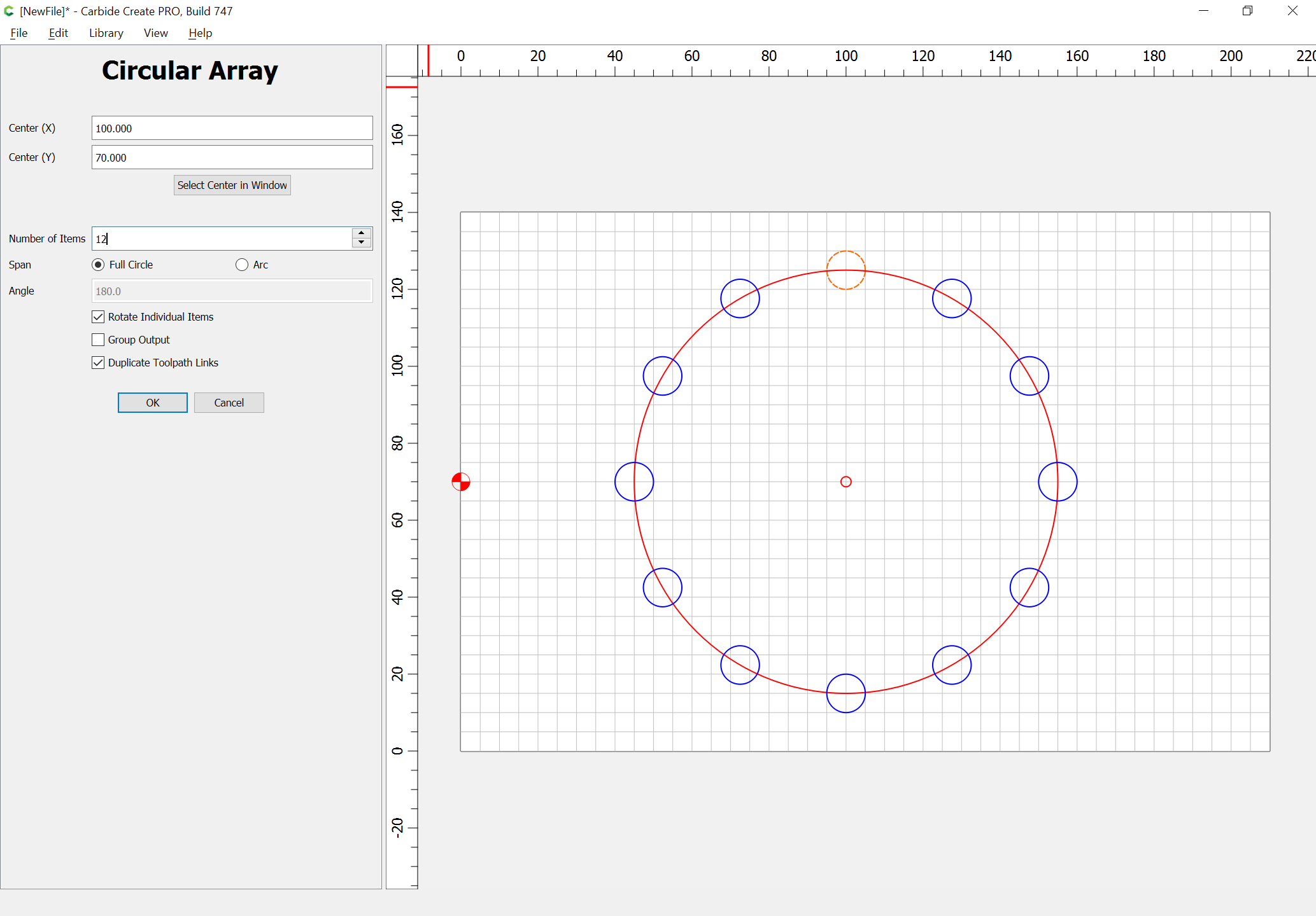
For Array, select something:

Thanks but I’m not finding the toolbar with the “send” arrow.

I figured out “array” but now I see I cannot change the dimensions of individual parts, it’s fused together?

No biggie, I now know how to create each rectangle and put it in place.

Now I’m asking how to move the grid so I can zoom in wherever I want.

Can I email you a jpeg?

Yes, many of the functions in CC are not associative or parametric. Once the object is created, it’s just there.

You can’t move the grid. It’s always positioned from the lower left corner of the workpiece. You can only change the spacing. You can however, move the geometry relative to the grid, work on it then move it back to where it was. You have to get creative sometimes, and it helps a lot if you stayed awake during math/geometry class in school. :laughing:

thanks. the only way I see to zoom, it with the roller on my mouse. When I zoom in, the grid slides to the left, going out of sight. I’ll try to just move the work back into view.

centering the long rectangles on the inner polygon, I see no way to snap node to a center point, will have to align each one by eye. ??

Certain types of objects will have a center point.

You can pan around w/ a right-click-drag

Please see:

https://carbide3d.com/carbidecreate/shortcuts

and

The toolbar w/ the “Upload” arrow appears each time you do a reply — this may depend upon permissions — I’ve upgraded your account, so if that was it, you should see it now.

You can e-mail a file in to support@carbide3d.com

sorry to ask so many questions, but I cant find any database to search. You’re my only source.

In “polyline”, is there a way to input length and angle with keyboard? The mouse is not accurate or controllable for precision.

when each is selcted, i see the “midpoint” on the central hegaxon sides, and on the connecting end of the long rectangles. But the two “midpoints” dont snap together.

Spiraphone 4.c2d (50.1 KB)
spiraphone 2

Okay, we got a sketch at support@carbide3d.com:

so to re-state the problem, we want 12 rectangles, of increasing size, which are radiating out from a central circle, so that their increasing distance creates a spiral.

Since we don’t have dimensions, we’ll start w/ some arbitrary ones in a drawing program which has a feature which will obviate that need.

I sent files from your Carbide that are dimensioned, but it seems you cannot select a rectangle and see it’s parameters, except sometimes (4 out of 12 show the parameters, 8 do not)

EDIT: As noted below, the .c2d file above contained a set of rectangles which were supposed to be the correct dimensions, so was used instead of the proxies which were to be be made, eliminating the need for the work-around in this post.

Import the pixel image as a background for reference:

We draw a pair of objects to get a rough approximation of size and rotate them to the same orientation:

and use them to get a pair of rectangles equal to the largest and smallest size:

which we then blend together so as to get as many rectangles as are necessary in a series of graduated sizes:

which we then export as a vector graphic which can be imported into Carbide Create.

Rectangles cease to be rectangles when they are rotated.

You can use this set of instructions w/ a set of actual files presently.

Alternately, we import the .c2d file:

and unrotate all the rectangular elements:

We then stack and align them all:

And position the dodecagon in the center and the collection of objects relative to it:

However, this will all be much easier if the Stock area is symmetrical:

We then select the stack of rectangles and use a Circular Array:

Then it is simply a matter of deleting the unnecessary objects:

and off-setting by the amount which one wishes to have around the rectangles:

And then drawing a Curve object to create the desired spiral — probably the easiest way to do this is to Node Edit the offset geometry:

deleting the unnecessary nodes:

and smoothing out the balance until one arrives at:

Attached as a v7 file.

Spiraphone 4_v7.c2d (56 KB)

Please verify and adjust as necessary.

wow - thanks …

My apologies, mean to go back and remove that post, since I worked up a set of instructions using your .c2d file, so instead, it is obviated.

1 Like