I have, what I assume is the newest Shapeoko controller board 9it just arrived Thursday). What is the relationship between Y1 and Y2 on the controller board and Y-right and Y-left motors? And where do the three limit switch wires go on the controller board.
Jeff,
So we are all on the same page (in case there has been an update that we are not familiar with), how about a picture of the entire controller board (showing the plugs in question.
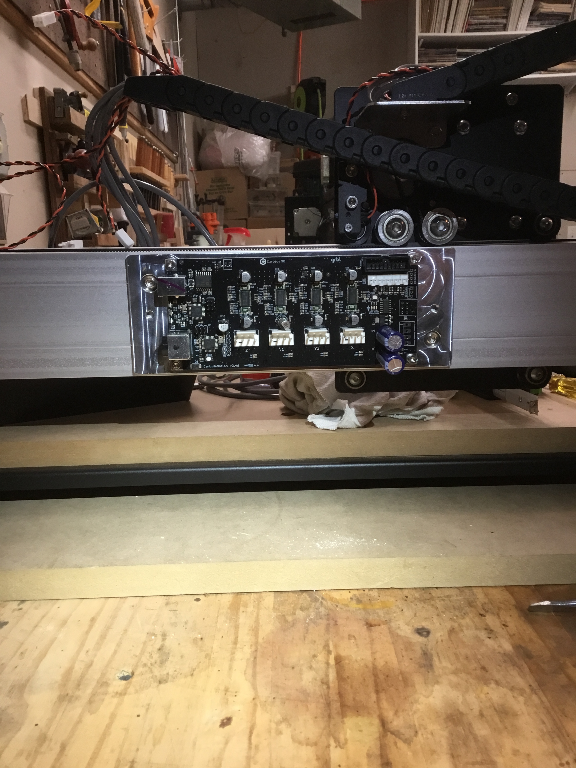
It’s clear where the z and x connectors go, but there is no information linking Y1 And Y2 to either motor right or left (viewed from the front-controller board on the left).
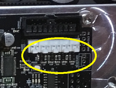
Also, while it appears that the limit connectors likely go upper right on the board ( white connectors) there are three limit switches and 5 connector positions on the board. Logic would have me guess left to right for the first thee positions. No clear instructions were included with the instrument on this…but I will say nearly everything else was either clear or obvious, even though the instructions were for an earlier model…
They are specified on the silkscreen just above the connectors in about 4 point font… They are X Y Z from the left most pin toward the right. The last two are for other accessories.
Not to be a DIck here, but try turning your camera in landscape mode and getting CLOSER so we can see the ports. I CAN see that it is Ver2.4 The same version I am running, and I am 99.44% sure that the plug in my picture has ID’s printed on the board (Mine did)
The Y1 plug on the Left goes to the Left Motor, and Y2 to the right. If you get these wrong, Hello World print will be upside down (No harm), and so just reverse them
Thanks. I appreciate the help.
Does that mean you’re all set?
Yes, thanks…"Hello World’ worked fine.
3 Likes
Thanks! I was struggling with this one too.
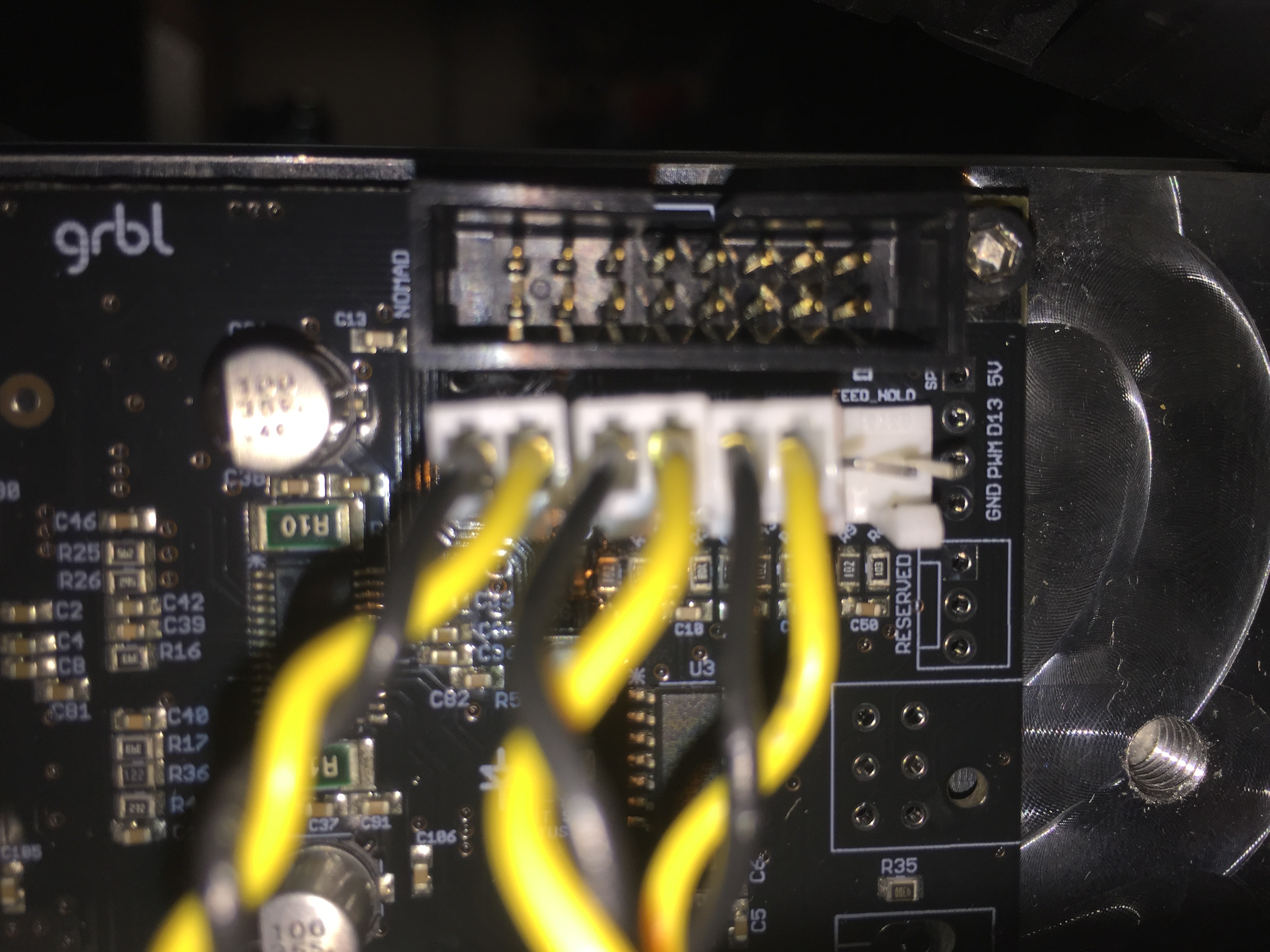
I finally was able too see the tiny markings between the black connector above the white connector:
(Left to right)
X Y Z Probe Feed Hold
Hopefully, I plugged them in correctly.
I don’t know what issues I will have to deal with yet, I haven’t started up the machine yet.
Even though the locations for the limit switches are marked they are not obvious and difficult to read if lighting is not optimal.
That’s all. I just hope that I installed them correctly.
Otherwise there is a fit issue that so will ask about on the forum in a different topic.
Just got done getting mine set up today with the limit switches. If it’s not correct it will let you know by grinding the belt, just have the off switch handy just in case…
Ok, probably testing Tuesday.
Thanks for sharing your experience.
I’m actually taking time to assemble this.
I already made one mistake with the rails.
Back to my assembly issue:
So, almost all of the M5x20 machine screws catch some thread through the plates into the base of the end parts. I hope that makes some sense. It’s just that one of these screws is not catching on the final corner screw hole.
Either this one waste board countersink hole isn’t deep enough, the waste board is too thick, the pass through hole is not located correctly or the plate hole is not located correctly.
Maybe, I can flip the waste board over to verify screw hole locations? Just an idea.
I have tired to modify the hole in the waste board and things are still not working. I can’t even thread the screw in from the bottom up, it lifts the waste board.
I’ll get back to my shop on Tuesday to try and resolve this issue.
There have been a couple of instances of not deep enough countersinks (and also some too deep requiring washers).
Swap for an M5x25 from some other part of the machine? If you’re out and about, any hardware store should have M5x25 — contact support@carbide3d.com and we’ll send you some if that seems workable.
Post a photo?
OK, I’m back on this issue this morning.
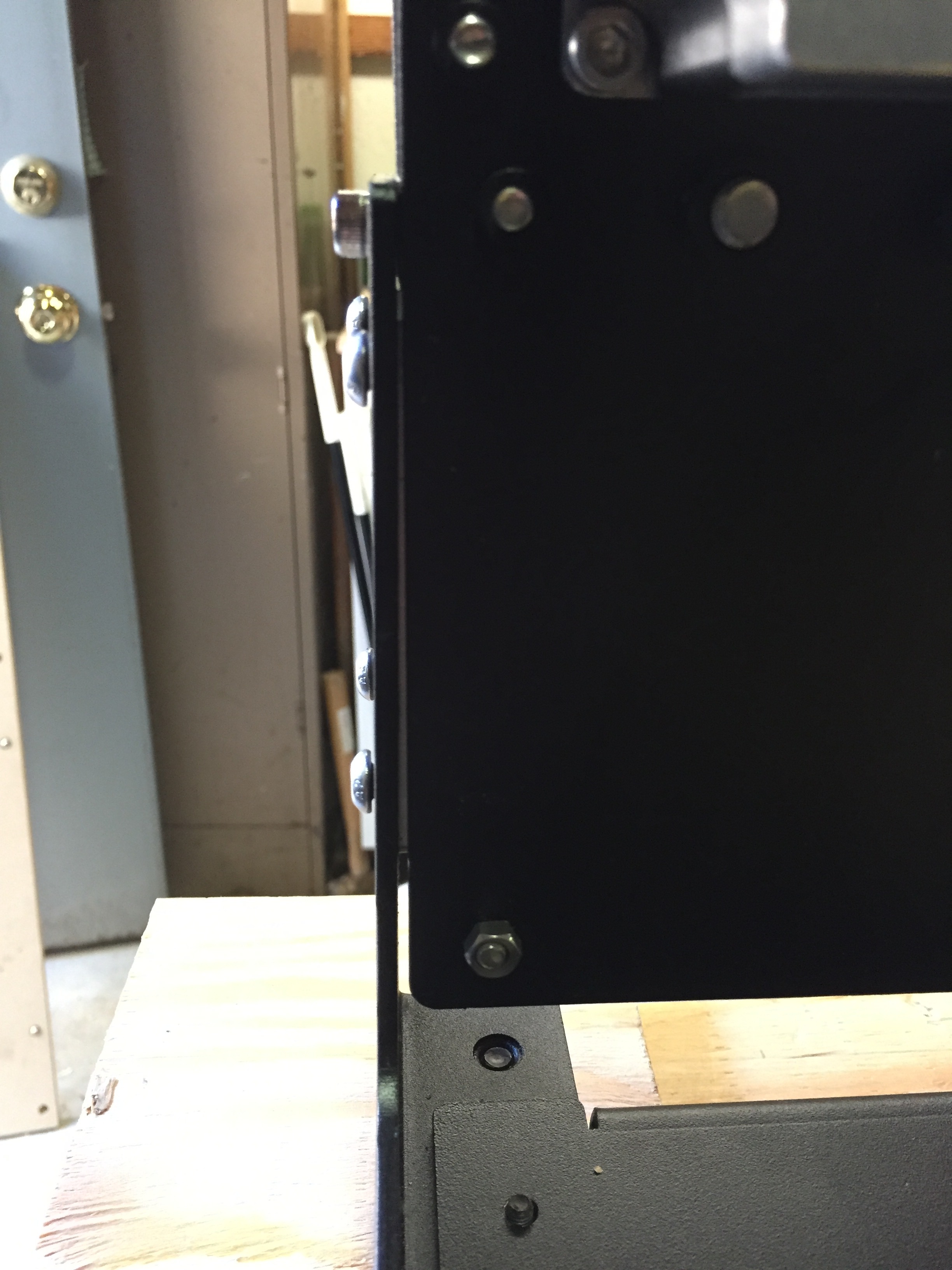
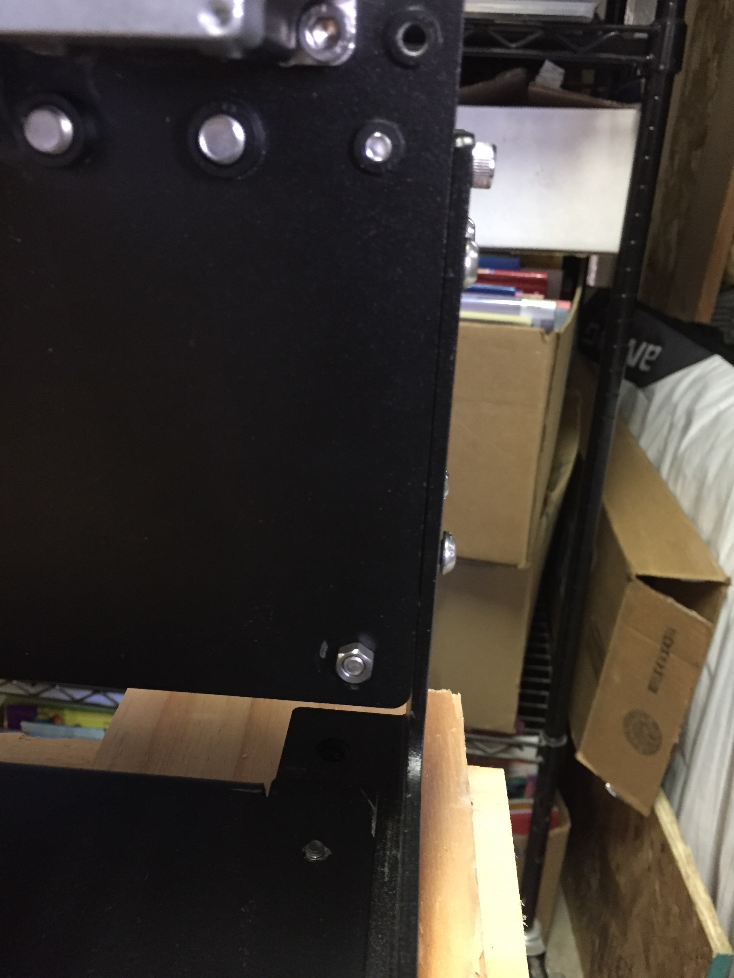
One of the axis plates is slightly bent.
(See photos)
This “corner” is diagonal from the corner where the problem was discovered.
Just to refresh, I’m trying to get this XXL squared.
Thanks!
Tem
Are you sure that it isn’t that the extrusion is not cut squarely? Or that the holes for the top V-wheels on the gantry motor mount plates aren’t level?
Usually, I find it best to just start with zero assumptions, then begin by leveling the table, then checking everything for plumb and square and level to that reference — check each part in turn until you get to where you need to begin making adjustments.
Official instructions:
Squaring Gantry to Front/Rear Plates
- Loosen all of the screws that hold the gantry together (4 on each side), these should still be loose from the initial assembly.
- Loosen the screws that hold the Y axis rails in place (16 total). These should also still be loose from the initial assembly.
- Slide the gantry to the front, so both Y plates are touching the front plate.
- While holding the gantry against the front of the machine tighten the front of the Y rails (8 total)
- Now - systematically begin tightening the 8 bolts on the gantry. Work your way from left to right, going back and forth in a X pattern (similar to tightening the wheel of a car).
- After the gantry has been secured, slide the gantry to the rear of the machine and tighten the 8 screws while keeping the gantry pressed against the rear plate
Be certain to loosen all the screws.
(copied from: http://www.shapeoko.com/wiki/index.php/Calibration_and_Squaring_the_Machine#Shapeoko_3 )