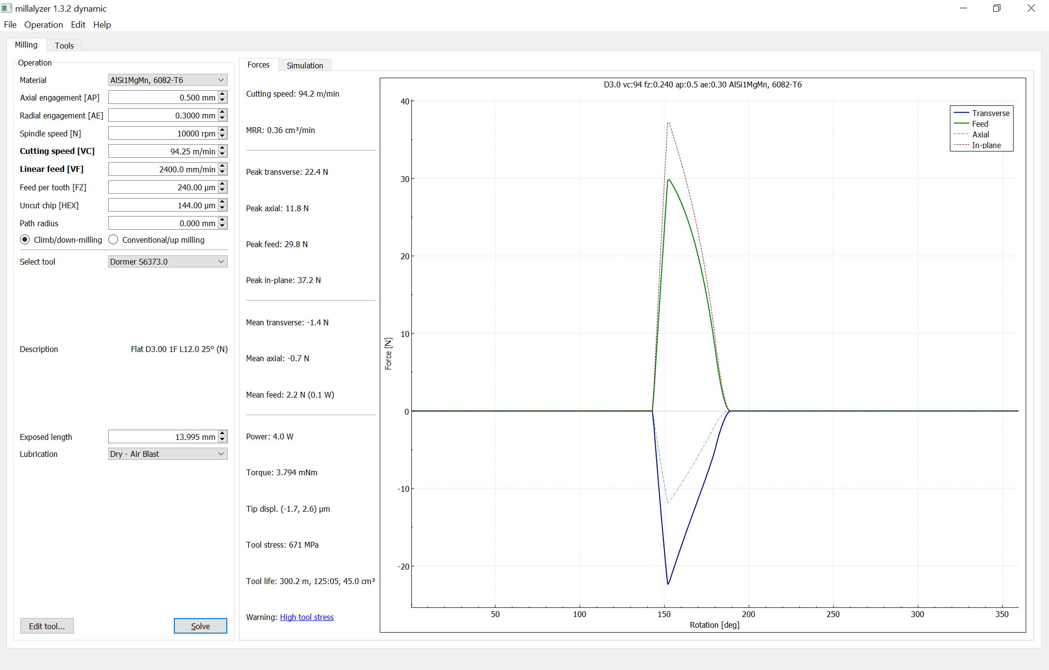
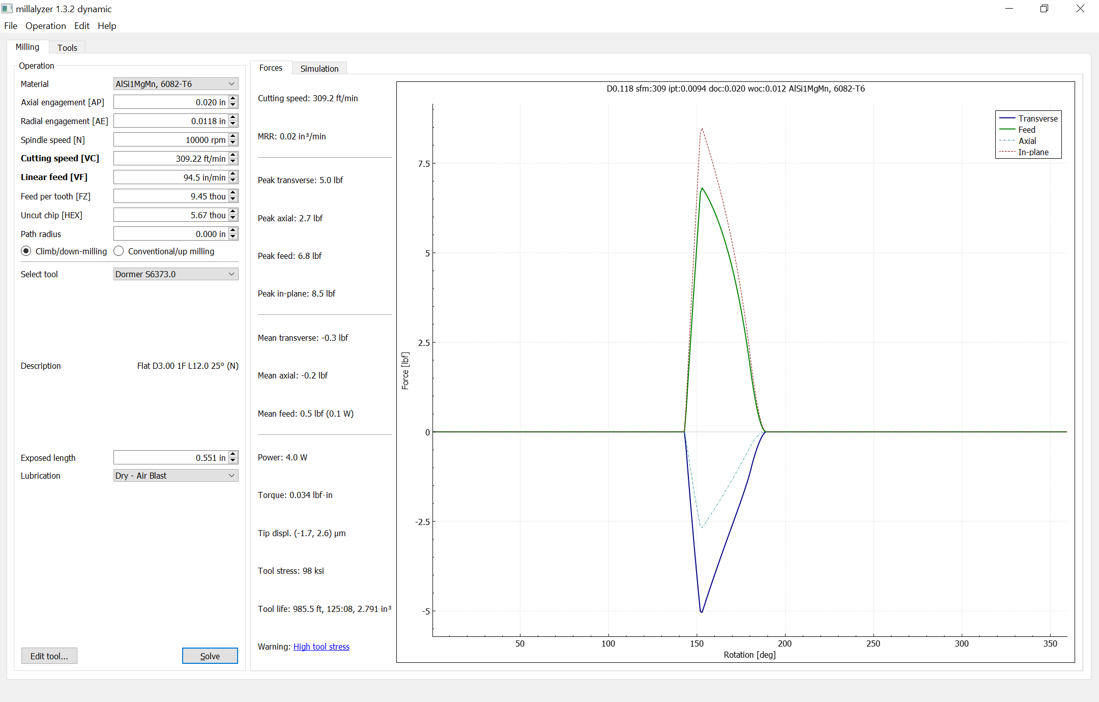
It has settings for transverse, feed and plane but they don’t appear to help here.
Cut
Feed
Transverse
Plane
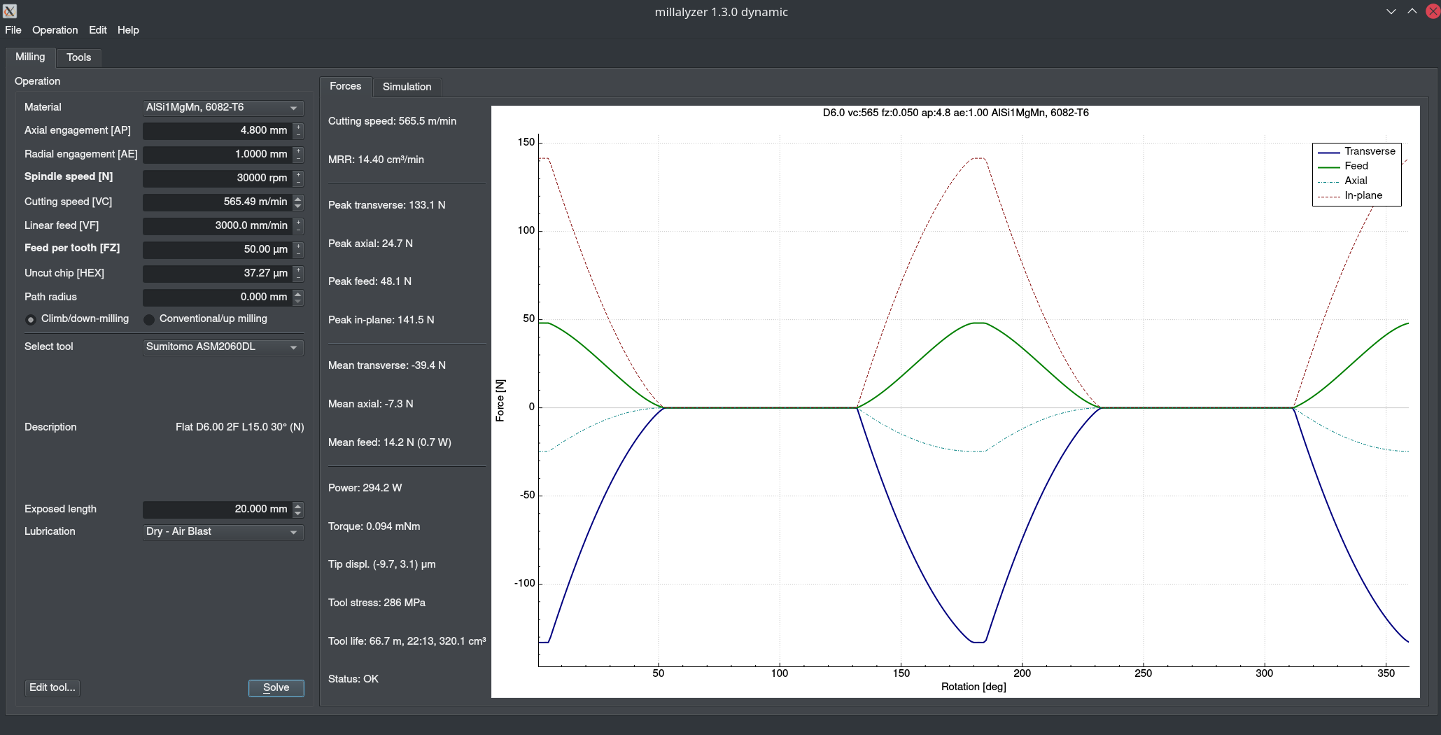
4.8mm radial, 1mm axial
12.1
17.6
18.3
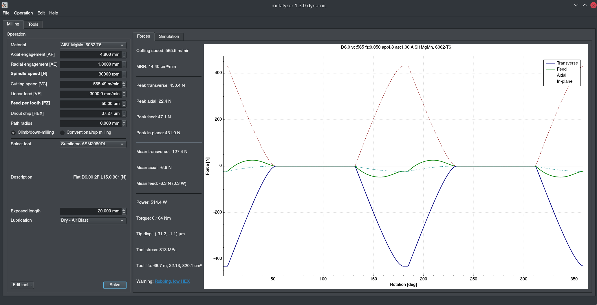
0.5mm radial, 4mm axial
8.3
8.2
11.7
The low-radial, high-axial cut has lower forces in every respect and yet it just doesn’t work and becomes a chattery mess.
I don’t think that’s necessarily crazy, you just have to adjust the width and depth of cut to compensate. When doing adaptive toolpaths for example, I’ve pushed 3mm single-flute endmills to 2400mm/min at 10k RPM (nearly 5 thou FPT) but I did it with IIRC 0.3mm width and 0.5mm depth.
Well friction is the product of the coefficient and the force applied so yes, it should, but it also reduces the amount of heat carried away with the chip. I don’t know how those two equations balance.
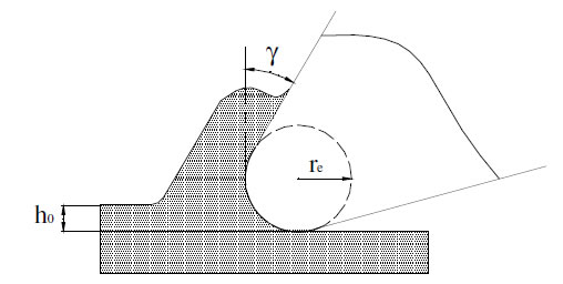
The most important aspect regarding chip thickness is that the edge is never perfectly sharp, but looks more like this:
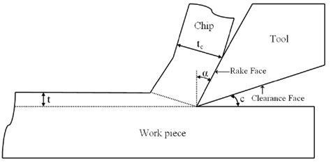
h_0 is the chip thickness here, and in this picture it’s smaller than the tool edge radius r_e. The tool is kneading the material in front of the radius instead of shearing it off. What you want to happen is more like this:
Here the uncut chip thickness (t) is much, much larger than the edge radius. I think it’s fairly intuitive that the second process is more efficient in lifting off the chip from the stock.
This doesn’t mean you should go for the largest possible chip thickness (feed), but stay well away from the edge radius. Hence the minimum chipload guidelines.
True, but it is concentrated to a very small area as well. The temperature inside the shear zone, right ahead of the edge, is often 200 degree Celsius when cutting aluminium at high vc.
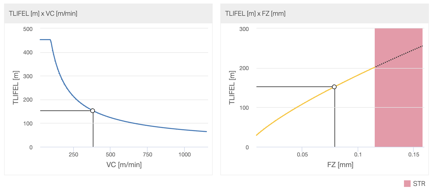
Yes, that’s about it. It’s not so much the heat itself (in aluminium at least), but the softened and very sticky aluminium sliding over the rake face. Every time it does that, it rips tiny tiny flakes out of the carbide - it’s visible if you have a decent microscope. So yes - tool life measured in meters cut usually goes up with chip-load. Here’s an example from Sandvik’s calculator:
Mind you, this is tool life in meters, or number of features produced for particular set of engagement parameters (recommended defaults for the tool). It gets more complicated if you start changing engagement as well.
How much tool life matters to you depends on how much you payed for your endmill, I guess.
Unfortunately cutter edge radius doesn’t seem to be available from manufacturers. What are typical values? Do most manufacturers likely use that or some other criteria for their minimum chipload (actually IPT?) recommendations? Can varying edge radius in Millalyzer be used to predict the impact? Is the argument that big chips help control heat valid?
If the tool is ground to a sharp edge, for use in aluminium, 3-5 µm. Some specialised coatings such as high-quality DLC add only 1 µm to that, but most are an extra 3-5 µm. Some manufacturers offer/advertise optional edge treatments, meaning larger, but well-defined radius (5-10 µm). That can have benefits (long-term consistency) for some applications where fz is very large anyway.
An endmill that is advertised as “universal” or “general purpose”, and which the manufacturer says may be used in steel will have a larger radius and a robust coating that add up to 7-15 µm. This is already painfully close to the chip thickness values that might be used in Nomads and Shapeokos.
Inserts for indexed tools have radii of 15 - 50 µm unless ground and polished.
Depends. Yes, it wears, but not necessarily quickly. If a 2-µm-radius endmill that is ground for acrylic is used in 7075, then you’re right, that edge won’t last long - and you can see that with the naked eye. That precise same tool in 5083 or 5754 (a.k.a. “dunno-which-alloy”) may well work fine for quite a while. An endmill designed for aluminium should be able to maintain its small edge radius (maybe 3, maybe 5 µm) for about the nominal tool life, and will certainly if lubrication is used.
In carbon steel, cast iron, graphite, cast aluminum alloys (Si > 5%) - absolutely. Wrought aluminium alloys - only where you can push large chiploads, so that the added radius doesn’t matter much.
Proper lubrication helps more…
Not sure. What is the definition of “control heat”?
So @Julien’s and @Vince.Fab’s empirically derived advice to not use chiploads (chip thicknesses or IPTs?) less than 0.001" is reasonable? Does increasing chipload ever help to reduce heat in either the workpiece or cutter; if so when? Is that as effective as alternatives so as flooding, cooling mists and/or lubrication?
The deformation mechanism in the first picture above (when the chip thickness close to, or smaller than edge radius) is less efficient, that is, larger forces are needed to separate the chip from the stock. Therefore, the amount of energy spent per material removed also goes up, and a fraction of that is converted into heat. So, increasing the uncut chip thickness (t or h_0 above) to a value that is a good bit larger than the edge radius will reduce the amount of heat generated per material volume removed.
However, if the reason you’re interested in heat in the first place is something like the temperature rise in the workpiece, then of course the absolute (not specific) amount of heat power in relation to heat dissipation is more relevant. Meaning cooling or reducing RPM.
What uncut chip thickness to edge radius is required to sufficiently minimize the amount of heat generated? Is there value in further increasing the uncut chip thickness to increase the proportion of heat carried away by the chips?