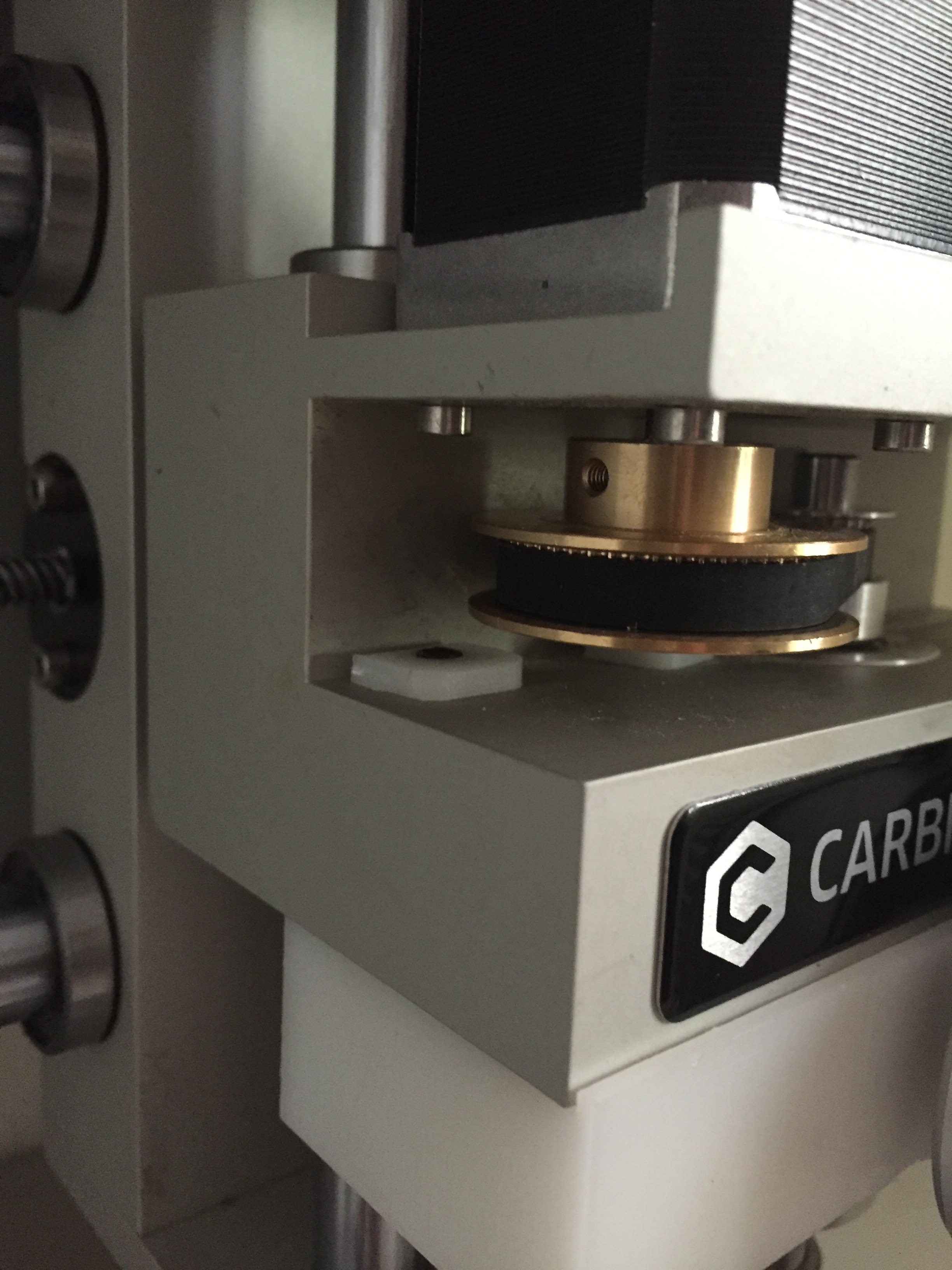
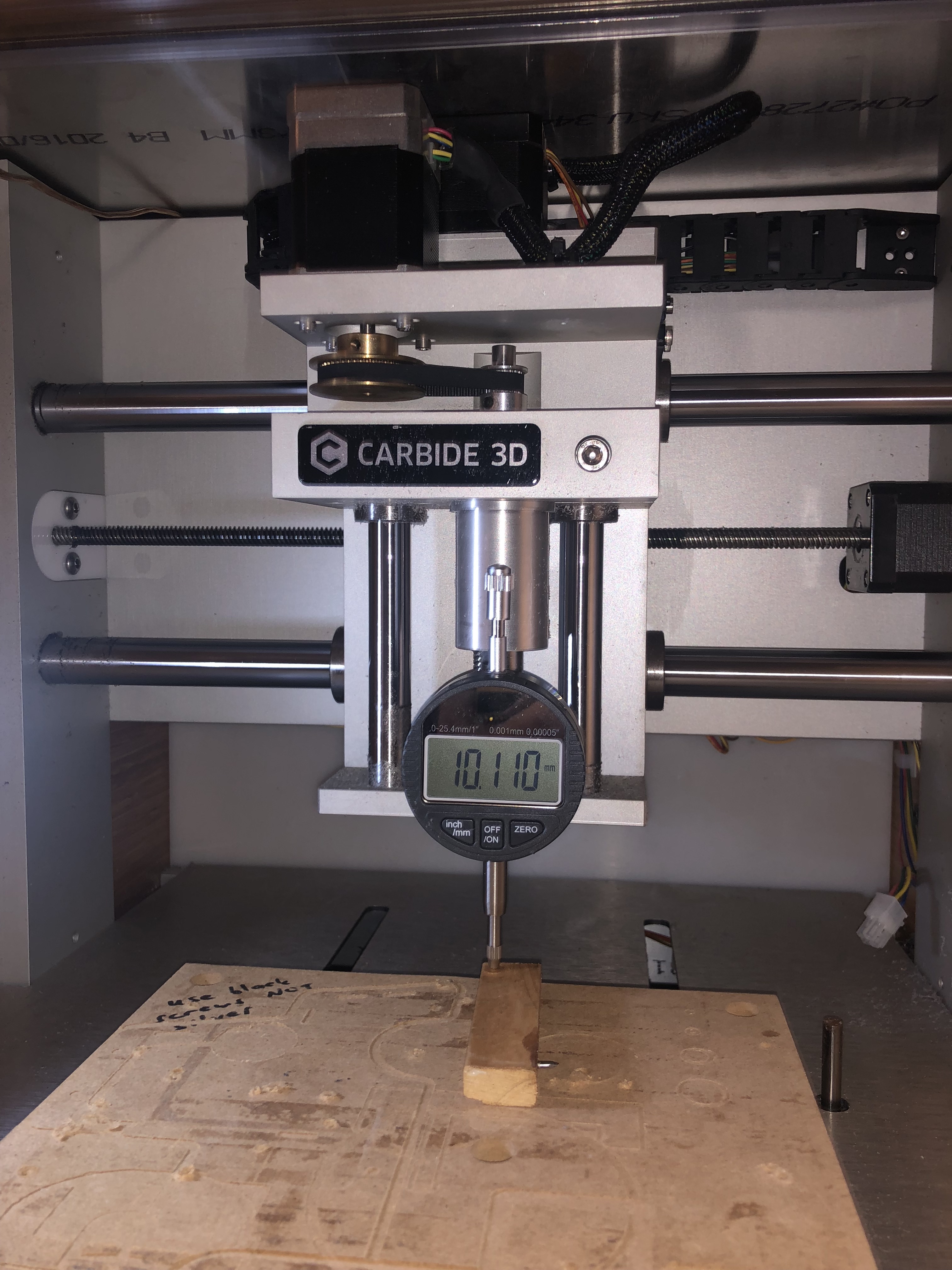
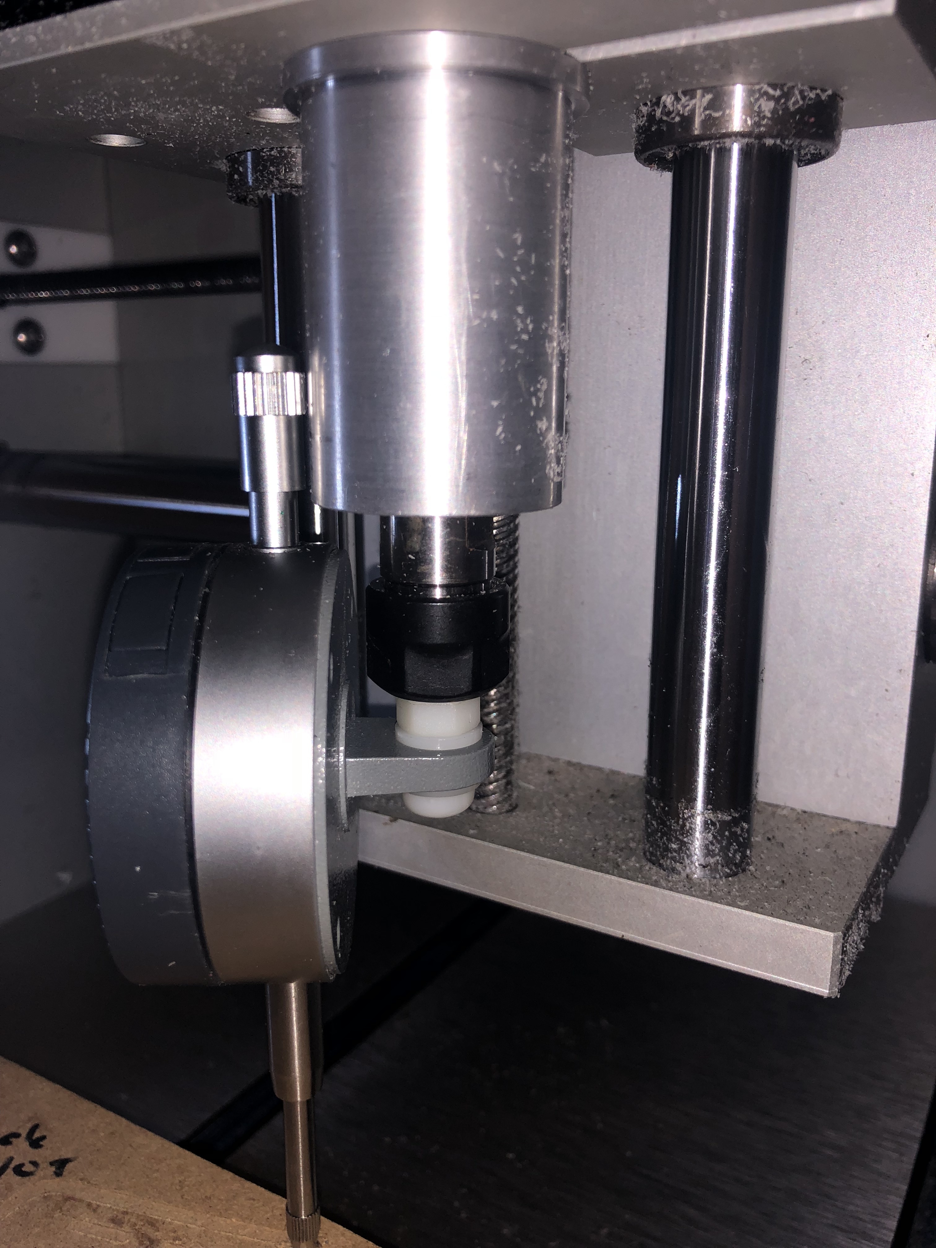
As mentioned in another thread, I have created a mount that allows me to attach a dial indicator to the carriage of my 883 pro, allowing useful things like precise stock levelling and a no-paper no-rub method of zeroing the Z axis. The mount also has a bunch of threaded holes to allow future mounting of other accessories (TBD but things like a laser cutter, compressed air are being considered)
There aren’t actually a lot of handy mount points on the carriage, and given the fact I wanted this mount to have a lot of “meat” for accessories and also preferred not to clamp directly onto the spindle the only option was to “borrow” the two holes that allow access for spindle motor adjustment.
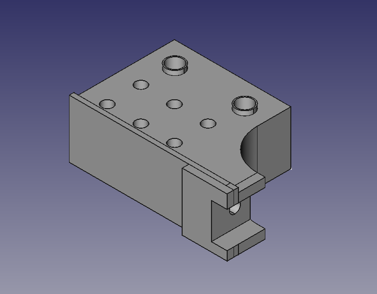
The CAD came together after keeping my head inside the Nomad for about an hour making and remaking measurements of the carriage. Was hoping for a single sided CAM job, but the slot and hole for the dial indicator meant the mount was going to be milled on two faces.
Have been toying with the same idea for a while but decided to place a dust collection boot instead. Would you be willing to share your model!. Id be interested in the measurements and placement of things. Great gob!
Edit: my excitement got away with me. Just realized you own a Nomad Pro. I have the classic. I think measurements are not the same.
I noticed that the back of my dial indicator is screwed on. I will simply nut a bolt through the mounting hole and engage the bolt into the collet. When I need a 90 degree reading than I will unscrew the back, rotate 90 degrees and rescrew it . A simple approach to a complicated situation. How bout that ?
Although I have the Shapeoko 3 not the Nomad.
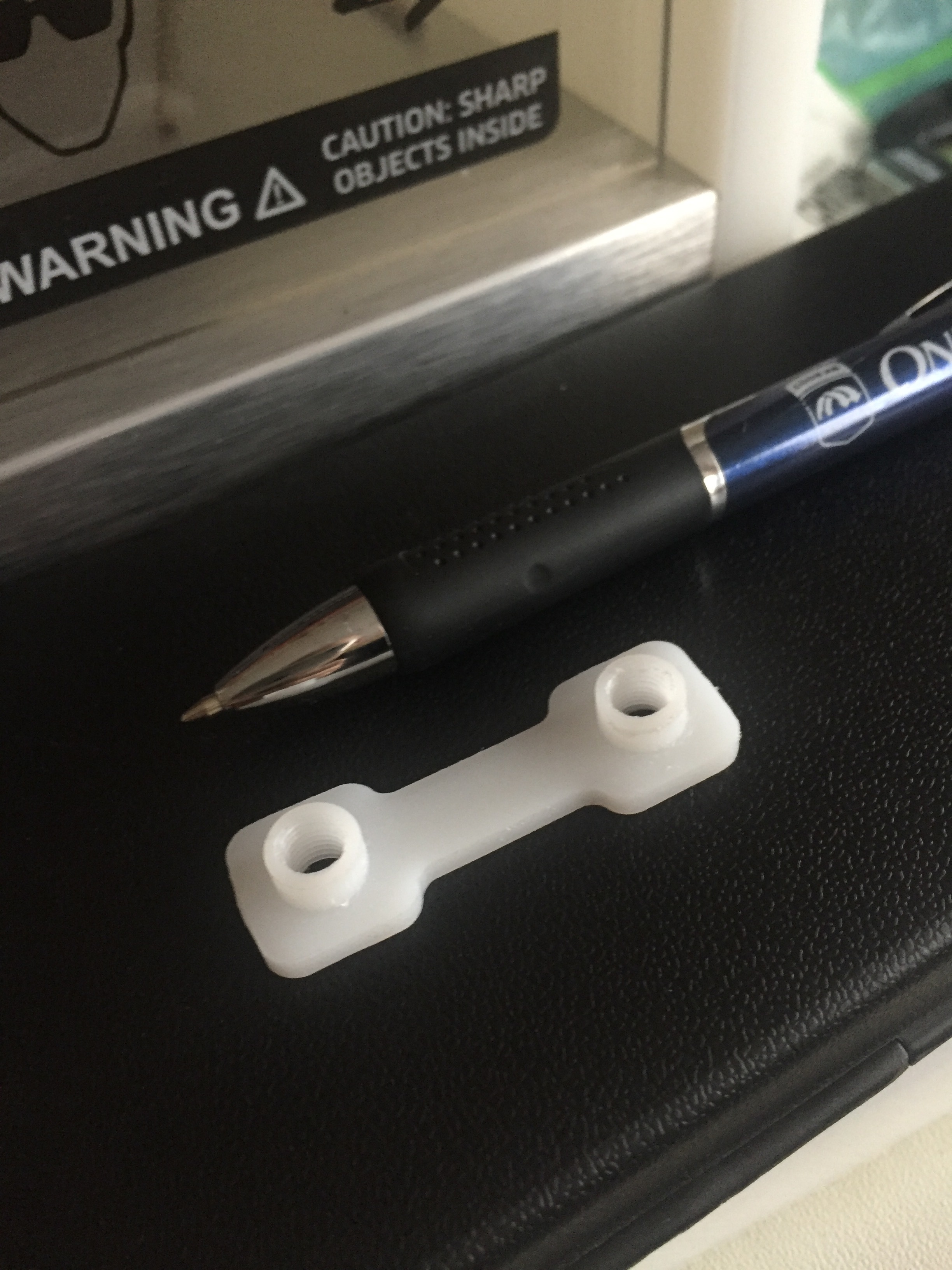
Just HDPE. You are reading my mind however - once the design is settled down as to all the possible accessories I am planning to redo in Delrin or aluminum. The only risk at the moment (I think) is the threads stripping out of the inserts, but the M6-1.0 threads I have in there now seem to be holding up for now.
Yeah, I spent a fair bit of time thinking about a collet mount indicator (and am still playing about with a spindle mount horizontal dial indicator plan and what I really desire - a spindle/collet mount probe plan), but I am already bumping into the Nomad Z height limitations frequently, and losing more Z height with a collet mount was just going to make the whole thing worse. The mount actually started out as a generic mounting block for accessories and then morphed into a dial mount as well when I noticed that the bed of my Nomad wasn’t as perfectly level as I needed it to be.
I don’t have access to a Nomad Classic, but in pictures it looks like it is almost a mirror of the Pro. Even more access holes to use so definitely the same concept should work. STL uploaded anyways, can share the FreeCAD file if it would help as a starting point.
Great idea, but how do you know how far you have the cutter up into the collet? I guess you could just always put it in as far as it goes but that sort of minimises the use of the full length of your cutters.
The primary purpose is less about zeroing Z and more about leveling stock/part faces (particularly handy when a part has a non-parallel side opposing the face to be milled) and confirming stock flatness (particularly useful when engraving) to a high degree of accuracy by tramming the dial indicator across the stock/face but it could be used for Z zeroing as well.
(1) lower the carriage until the dial indicator is compressed on a known level surface - bed or stock previously levelled with the dial indicator. zero the dial indicator
(2) loosen the collet and lower the end mill so it is resting on the bed or level stock. Tighten collet
(3) move the dial indicator above the area where the Z zero will be done. Adjust carriage Z height to read zero on the dial or a required offset to dial zero. Set Z to zero in CM or equivalent.
I wouldn’t say this is particularly handier than a usual Z zero other than allowing one (a) zero quickly between different jobs/faces after leveling if you don’t have to change the tool (b) to accurately set a Z zero where the Z zero is a set offset above another surface, as can happen when you have to mill multiple faces of a part.
You are correct I suppose - I hadn’t thought of it but one could also insert the end mill all the way in or use a depth stop on the end mill to ensure it is consistently at the same length, thus allowing one to skip the dial/end mill alignment in steps 1 and 2 above once set up appropriately.
EDIT: Actually I was pondering this earlier in the day and the workflow of Carbide Motion with the Nomad tool length measuring allows you to do exactly what @1st_Kiwi_Nomad proposed. You put a fixed length “reference” pointer in the chuck, which CM measures as “tool length” before jogging. Drop the carriage with the dial indicator onto the stock to a pre-determined depth on the dial matching the reference pointer tip. and set Z zero in CM. Once the CAM file is started, CM asks for a tool change and you insert the appropriate tool, no need to insert completely into the collet or use an end stop. Once tool is changed CM goes and measures tool length and applies the appropriate offset anyways. Curious how accurate/repeatable this might be - will have to give it a try.
Yeah, or you could just wait for the touch probe to get released… It’s supposed to be ready this week.
You have made this DTI mount really nicely mate! It really looks good.
Thanks! - hope it proves useful. Yup, very excited to see the touch probe released and for 2 sided window machining it should be the bees knees. It’ll be great for square stock but some of the odd shapes I deal with mean manual zeroing is going to part of the workflow regardless I suspect.
The only minor quibble is inadvertent spindle rotation moves the measuring point. Theoretically it’d be possible for the spindle driver to electromagnetically lock the spindle position, but for simplicity I think I’ll 3d-print a small fixture to stop spindle rotation when the indicator is in place.
Am already planning to read the indicator electronically and probe a matrix of points to build up a z height table. This will be a precision measuring system as well as a handy way to manage warped copper boards for milling circuits.