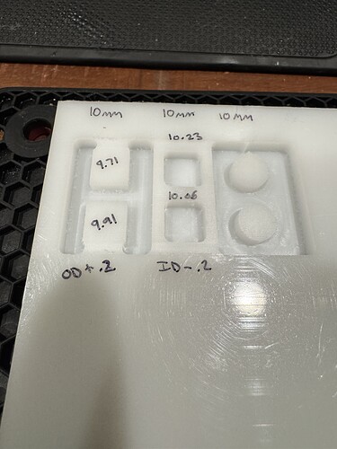
HELP! Using a Carbide 3D Nomad cutting HDPE. All squares and circles should be 10mm. Outside edges are all about .3mm small. Inside edges are about .2mm larger and consistently so. I have been correcting it by increasing/decreasing the size by .3mm or .2mm in CAD. The lower samples were with the CAD model size increased. Is it just my motor’s steps per rotation that is off.
Since both the inside and outside dimensions are off by about the same amount, and in opposite directions, I don’t think this is a steps calibration problem, or at least not just a calibration problem.
To see if is a calibration problem, try doing the same experiment with 20mm dimensions. If it’s a calibration problem, the error will double.
It would appear that what you are seeing is consistent with the bit cutting oversize. This could be because the bit actually is oversize, or because of run-out.
One thing you could try is rather than changing the pocket size, change the diameter of the bit, by double the amount of error you are seeing. Since the inside and outside errors are different, I would average them.
I measured the bit and it is 0.125. I will try cutting a 20mm test tonight and see if the error doubles.
Uploading: IMG_2981.jpeg…
I ran the 20mm test and was still .2mm under on outside walls and .2mm over on inside walls. I have checked all the fasteners and they are tight. Haven’t taken it apart yet to check the back last nuts but will if I need to.
Since the error is about the same, I think we can rule out calibration. I think you are looking at runout - the degree to which the bit and spindle do NOT run perfectly centered on the center axis of the bit.
There isn’t much you can do about it. Since it basically makes things cut wider than they really are, your best bet is probably to change the bit size in the tool-database, so that your design program is working with accurate numbers.
I found slop in the gantry. If I push to the right against the spindle it moves the tiniest bit. Probably .2mm. Gantry is solid in every other direction.
I am fairly new to CNC. Would I change the bit size to .1mm larger or .1mm smaller in the software. I am assuming .1mm because I need it to remove .1mm on all sides to equal the .2mm overall size difference.
Sorry if this is a step in the wrong direction, but how is the material being held down. Is it possible you are seeing the material being moved (lifted, pushed, etc) in a certain direction due to the cutting forces.
If you are using two sided tape, you may be measuring it’s flexibility.
Agree with Michael about the possibility of runout. A way to check this if you have good inside calipers is to cut a slot the single width of the bit and measure the width of the slot.
As far as compensating for the actual bit size if different from spec: since your bit is cutting too fat you would increase its size. Thinking the bit is larger than the nominal size, CC will pull it away from the line so as to not cut as fat.
I am using carbide 3D tiger claw clamps.
Thank you. will try this!
I would reach out to support then. It sounds like your anti-backlash leadnuts on the X-axis might be worn out. If you are noticing error primarily in the X-direction rather than in Y, I would disregard everyone else’s suggestions for now as well… You may end up going down an unnecessary rabbit hole.
In which case cutting a vertical as well as horizontal slot will tell. More of an ant hole versus a rabbit hole.
I have a X axis backlash nut ordered.
SOLUTION!!! I just learned how to install a collet into a collet nut… I was loosely setting the collet into the nut, aligning then installing onto the spindle. turns out that is wrong. Snap collet into the collet nut then install on spindle and then insert endmill… The simplest solution is often the right solution. My accuracy is perfect now. Thanks to everyone that replied to help me.
This topic was automatically closed 30 days after the last reply. New replies are no longer allowed.
