I removed the Nomad’s bed from the machine, put it on the measuring table with a µm DTI mounted and moved the tip from the center towards each of the four edges, recording the difference between the minimum and maximum reading for each edge.
Yep.
The difference between the minimum and maximum reading using the 3D-Finder is ~45µm. With the DTI, it’s ~92µm.
And specifically, the 92µm variation is along the X-axis. Along Y, it’s only 30µm.
Seems like you’re finding the precision limits of the machine.
There’s evidently some flex or movement between the levelling pass and later measurement. This could be deflection in the linear motion parts (leadscrews, linear bearings) or it could be the machine frame moving.
And then there’s the underlying linearity error in the linear bearings, which seems to be concentrated in the X axis. It would be interesting to figure out a way to check the straightness of the X axis, is it high in the centre or at the ends? (wondering if it’s sagging with Z and spindle weight)
Hmm, the bed is bowed in the middle but interestingly, this is present on both sides of the bed, so the bed is actually a bit of a hyperbola along the X-axis:
The only think I could think of that would cause that is if the bed is under compression when it’s mounted to the Nomad, causing it to flex upwards a bit. That would cause a curve on the bottom side and a bulge in the top. By flattening it and removing the “bulge”, I would have created an intentation on the top side but the Nomad would see it as flat.
This theory seems to be supported by my before and after heightmaps. That “bulge” can be seen in the “before” heightmaps but in the “after” heightmaps, there’s no longer a bulge.
What does the bed mount on? Presumably this is not flat if it’s causing additional curvature? Maybe you can flatten or shim this mounting to flat and then be able to deal with the top side?
Some wet abrasive paper stuck to some float glass or your surface plate may help in getting the plate flat, once the mounting points stop distorting it.
I remembered, if there’s a reproducible and quantifiable issue with the Nomad like this, I can use my controller to compensate for it. It has a compensation mode for uneven surfaces which is mainly intended for PCB milling but is really just an XY->Z LUT.
I’m trying to think of how I could measure that though. My best guess is to take a straight edge (or another verified flat surface), lay it edge-up across the bed, and measure it with my probe. If the probe tells me the straight thing isn’t straight, it’s because there’s variation in Z across the X-axis.
The trouble is that my straight edge is too long to actually fit inside the Nomad… I have some other flat things that might work though (like some borosilicate glass). I’ll have to measure their flatness and see if they’re good enough reference surfaces. Otherwise I’ll just have to buy another straight edge.
I can do the same compensation on Y as well and then it should be possible to mill the bed properly flat…
Two ~8x100mm blocks separated ~110mm from each other, that stick up through the slots in the sheet underneath the bed and run parallel to the Y-axis.
I think the flatness is fine (and hope, since I can’t easily measure it). My theory is that either the two locating pins (one on each of the mounting blocks) or the screws, combined with slight differences in temperature or dimensions, cause the mounting blocks to compress the bed slightly.
It’s either that or I’ve mounted something to the bed tightly enough to distort it I think.
I bought some sheets intended for lapping but I think I’m going to wait and see if I’ll need to replace the X and Y axes first. If I do, I’ll need a new bed anyway, so I’ll just use pre-milled Aluminium plate for it.
I don’t have the book but I also came across this.
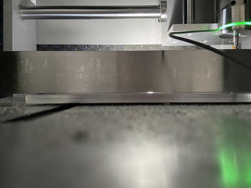
I managed to fit the straightedge on the bed and did some tests.
The bed is not flat along the X-axis, you can see light passing between it and the straightedge. The gap looks narrow but that’s because of my light source, that gap runs across most of the bed:
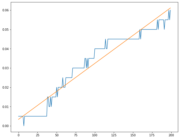
Sag in the X-axis probably isn’t a big problem but the machine is 60µm (~2.5 thou) from being square:
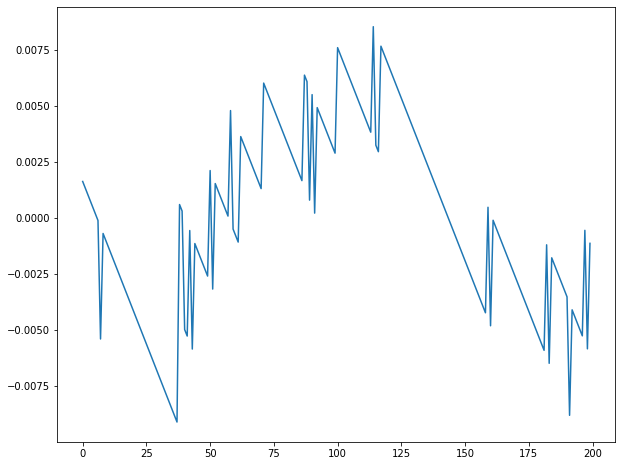
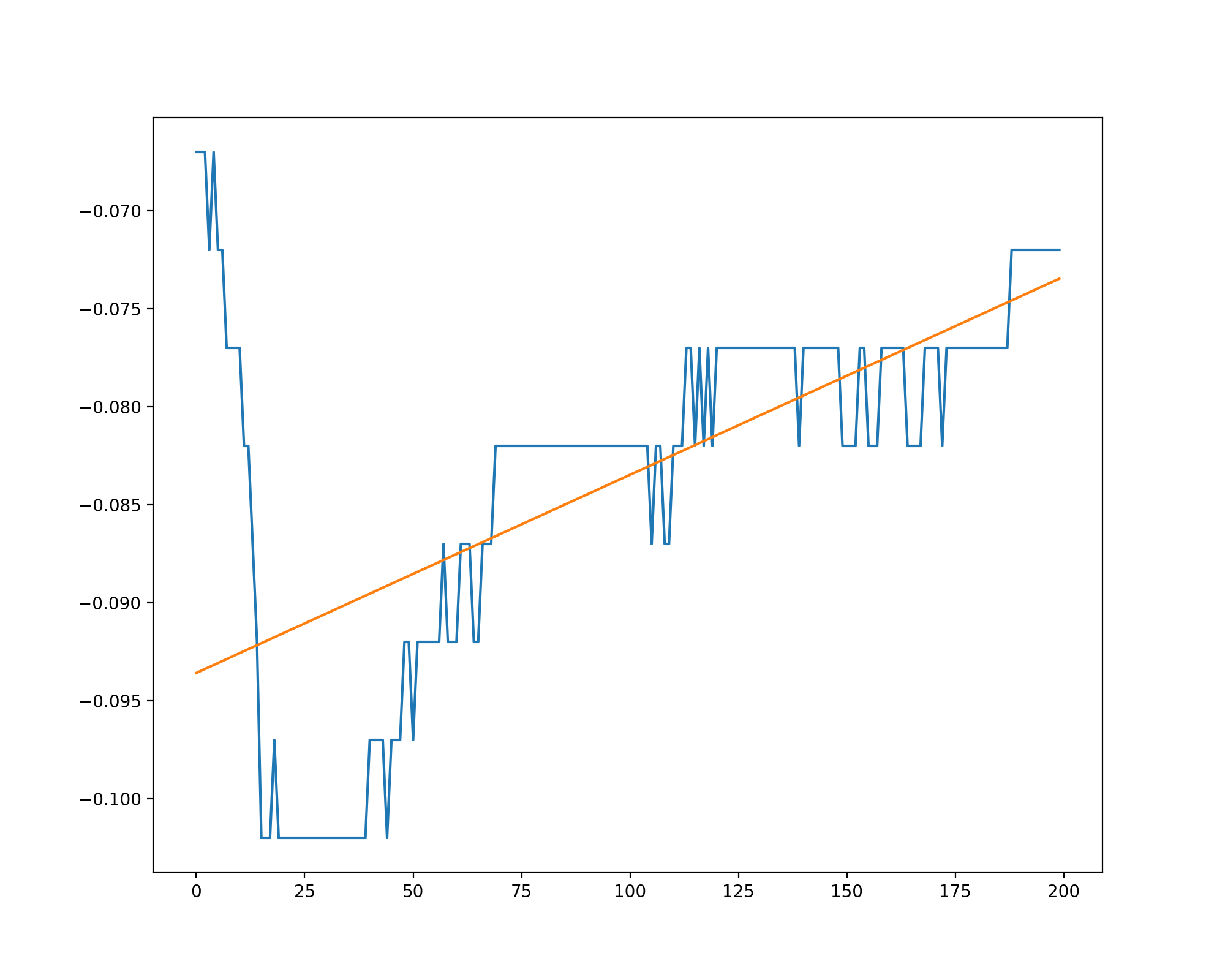
As for consistency, here’s deviation from straight:
It looks like there is a bit of a sag in the rails but it’s only ~15µm (~1/2 a thou?) at most.
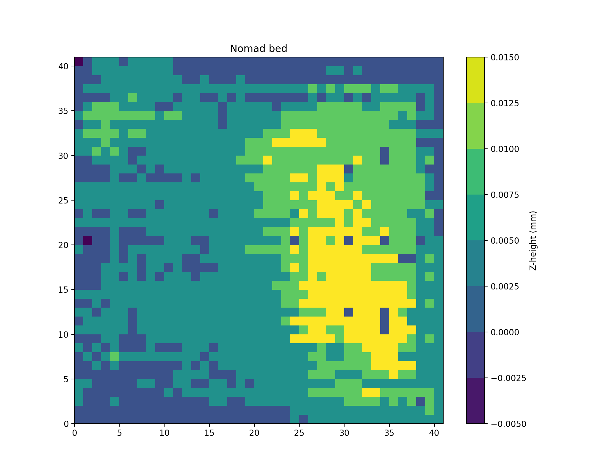
And for good measure, another map of the bed after remounting it:
Still ~40µm of inconsistency but at this point I think I’ll just make a new bed with pre-milled plate. That’ll also give me a decent reference surface to test against.