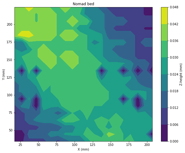
I was curious how level the Nomad bed was so decided to measure it. Since I have a 3D probe I can produce a nice 2D image of it, so here you go:
Those small 0mm spots in the image are from the mounting holes and screws on the bed. Those can be ignored.
I was surprised to see that the deviation is 0.05mm (I think 2 thou in Imperial?). That seems like a lot to me but I don’t know what’s normal. I suppose you’re meant to put something on top of the bed and then surface it anyway.
At some point production of Nomads included surfacing the bed using the machine as part of calibration/commissioning — not sure when that process was begun. Contact us at support@carbide3d.com and we’ll do our best to work through this with you.
I have one of the Nomads before the production surfacing. When it first arrived the front right corner was 0.35 mm higher than the front left corner. I can certainly imagine the MiC-6 plate warps a bit when getting tightened down, errors in the other parts add up, etc, etc. Resurfaced it and within .015 mm all 4 corners and the middle.
Call me odd but when I bolt the threaded table on top I do the bolt tightening in the same order I would when putting a head on an engine cylinder - center first then cross pattern. Does it make a difference? Probably not but it calms the demons in my head.
What I do need to do is surface the threaded table - that looks more like what you see on the bed.
The thought did also cross my mind that if one did bolt something not perfectly flat to the MIC-6 bed with enough torque and kept it on there perhaps that would eventually warp the bed as well? That bed is cast aluminum but not exceptionally thick. Not a metallurgist here…
The toolpath was just a basic climb milling face operation. I didn’t even use CAM for it, I just wrote a macro in G-code directly:
sub face
    ; X max, Y max
    #30 = 210
    #31 = 210
    G0 Z1
    G0 X[#30] Y0
    M3 S10000
    While [#5002 < #31]
        G1 Z-0.02 F300
        G1 X-5 F300
        G0 Z1
        G0 X[#30] Y[#5002 + 1]
    endwhile
    M5
endsub
It could be that my probing routing is off though. @Vince.Fab, how troublesome is it to remove the bed and reinstall it properly? If I can take it off, I can check it properly with a flat surface and a DTI.
Start at the bottom right corner of the stock, 1mm above it
Until the endmill is positioned below the top of the stock
Bring the endmill down to Z -0.02
Cut to X-5
Retract to Z1
Rapid to the right end of the stock, 1mm further towards the top on the Y axis
Stop
I’m sure there are some folks at SMW that have done this stuff that you could learn from, there are some damn nice machines there to play with. If you end up with a machine that supports macros and want to learn, let me know.
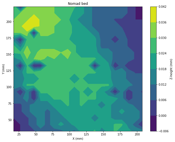
Quite repeatable. Here’s another, higher resolution map from a different run:
Hmm, a good question. Apparently the thermal expansion coefficient for Aluminium is 23e-6, so if the temperature varies by 15°C, I’m looking at 0.00345x expansion/contraction. The bed is 6mm thick so if my maths is right, I’m indeed looking at a 20.7µm difference, which might affect the results.
Okay, I pulled it off the bed and measured it with a DTI and it’s actually worse than the 3D-Finder reports. Running from the left edge of the bed to the right, straight down the center (i.e. along the X-axis), I see nearly 100µm of variation, around 6x what the 3D-Finder reports for that path.
So I suppose my machine isn’t square or the bed wasn’t bolted down properly.
Sorry, I meant to add, I did measure that on a surface plate (well, measuring table but it has 3µm flatness so same thing).
I also have a straight edge, I can try to slip shims in between it and the bed too…
We’ll see, I don’t think I’ll put too much effort into it just yet since there’s a chance I’ll redo the axes in the not-too-distant future. I’ve updated support though, I’ll see what they say.