Just got a nomad today, and I printed the wrench fine. However my Z axis is printing about .25-.5in above my actual stock material. Here is how I set the program 0, i clicked the upper left hand corner on the stock.
I defined the stock, i hit auto, my part is that exact size
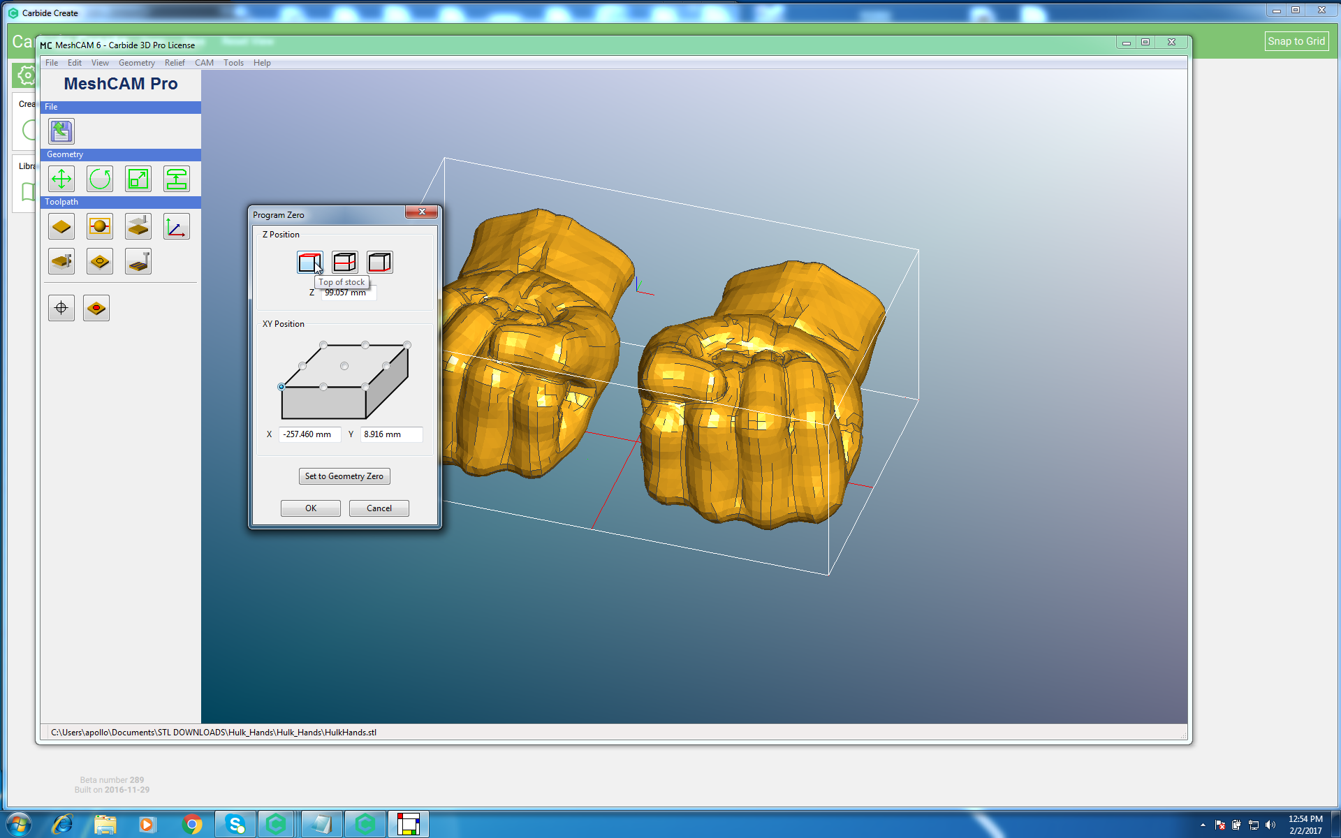
Here is a screenshot of the part:
Please see the imgur album since new members can only post 1 picture here: http://imgur.com/a/lxj4W
The Z seems fine in Meshcam am i wrong?
When i import it into Carbide Motion I load the file, then put my spindle to the upper left hand corner on the stock, then hit “Set Zero” then “Zero All” and then hit start. But the Z is always printing a little high.
Extremely advanced at CAD / 3D modeling and am a drafter, but CAM always has just baffled me, could someone please help?
Hmm what on earth. I have it set to the top, when i click off of the box it seems to switch back, i dont see the bubble filled in when i click on the setting.
But if it was on the bottom instead of the top doesnt that mean i will have a bigger gap now when i set it to the top?
Here is the Meshcam file, still looks as though my axis starts on the bottom of my mtl rather than the top, after hitting both bubbles.Sign.mcf (636.1 KB)
In my experience with your exact problem, setting the z zero to the top of the part never works. You have to set it to the bottom of the part. Meshcam simply cannot reliably generate -z dimensions.
I started using the front left bottom for zero, and the program works flawlessly every time.
Another VERY important thing I learned, set your z zero on your machine after you upload to Carbide Motion. Not before. For some reason, your zero gets garbled when you upload a file.
It took four months of frustration to finally see what was happening (I’m very busy, and didn’t have time to concentrate on the issue).
EDIT: It seems that it is the way i did the 3D model. I use Autodesk Inventor and flipped the extrusion direction and it worked. Is this a known problem / necessity when creating things for CNC Milling? I always try to constrain my objects properly on CAD. I GUESS it makes sense geometry wise that you would have do this, but it seems like this type of thing would be automated / more streamlined, well i learned something today!