I haven’t looked into it more than a quick google, but some variant of this looks almost like a drop in replacement. Am I hoping for too much?
My concern with that style of motor is that I’d like to put substantial axial load onto the screw and these motors either have no ratings or low ratings for axial load.
For example this listing gives an axial load rating of 25N/65N push/pull. Have a look at my cut from earlier and you can see that I easily exceeded 25N.
Compare that to the fixed support I used for my Z-axis: the load ratings are in the kilonewtons.
Ah, that explains it. I noticed in the product page you linked that they had ratings for single- and double-side support, which got me thinking: would it be doable to mount the integrated ball screw style with proper support at the opposite end of the motor?
I think from a physics perspective that should work but in order to put the other end of the screw in a fixed support, you’d have to get some custom machining done to the screw. I’m not sure whether that would be feasible, as it’d be difficult to put the assembly (including the stepper motor housing and ballscrew nut) into a lathe and I’m not sure if you can safely remove the ballscrew nut. You’d have to get the machining done prior to assembling the motor.
@Vince.Fab which screws/nuts specifically did you use? I detached the X-axis nut so I could easily get a look at the carriage and it looks like the cutout for the nut is 20mm wide. You said earier that you used 1204s like I did, were you able to find 1204 ballnuts with a 20mm diameter?
Hmm, I found a 12mm ballscrew with a 20mm diameter ballnut, the complication is that the pitch is only 2mm. I suppose the issue is that the higher pitch screws have physically larger bearings inside, and so need a larger diameter housing to contain them.
At the higher feedrates I’d be able to run with this spindle (e.g. the 3600mm/min I did before), I think I’d need to make bigger changes to accommodate this screw. 3600mm/min with a 2mm pitch is 1800RPM from the stepper. The stepper I used for the Z-axis can do it but torque would be ~0.2Nm.
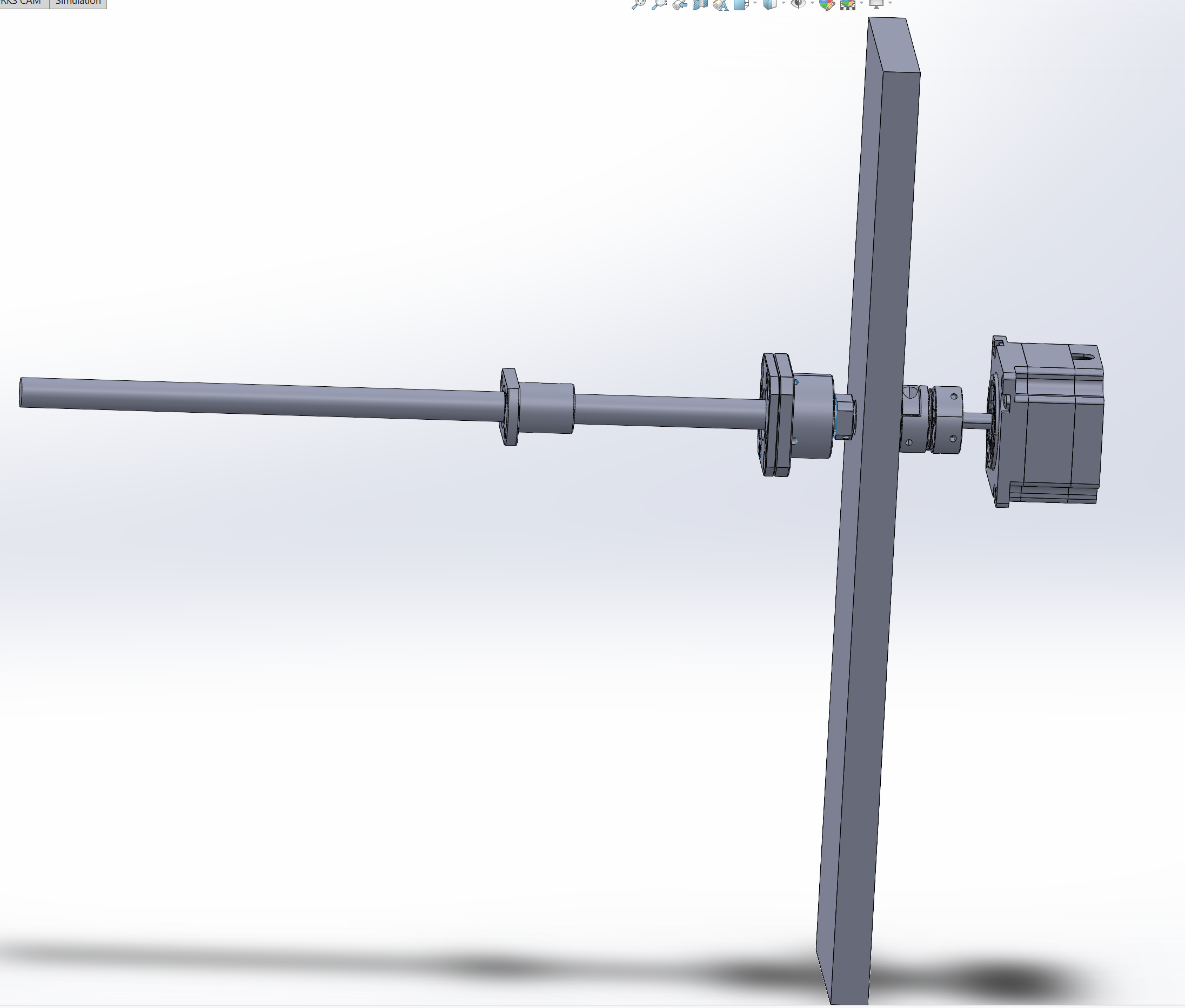
I also looked at the various dimensions and given I have the most space to spare on the outside of the Nomad’s enclosure, I think the inside would just have the fixed support for the ballscrew. The ballscrew end would protrude out and I’d put the coupler and stepper motor on the outside of the enclosure.
Something like this:
I also stumbled across these sexy things and I’m thinking of swapping out my stepper drivers (again) and going closed-loop. I think I can make enough space between the stepper housing and the coupler to fit an encoder. A 14-bit encoder is ~$50 and those drivers are hella expensive but I’d be able to reuse them if I end up upgrading to servos one day.
Or I could go straight to servos…
If you have the means to re-work the end of the screw (usually hardened to > 55 HRC), you could do that mechanically, but then you would have two fixed supports taking axial loads. You might get away with it, but that is not good engineering practice, because any kind of minor variation (thermal expansion of the base plate when the machine heats up, tolerance stack-up) will create very large stresses in the screw and bearings.
1 Like
Kudos! That’s a very serious upgrade, well done!
Good point but the chatter, as far as I can tell, isn’t really related to the feeds and speeds. The same feeds and speeds that work just fine on the far right side of the stock start to chatter on the left side of the stock. This was the same with the stock spindle so I think there might be a mechanical issue with the machine (like some nut being more worn out on one side than the other).
That’s interesting. Do you see the same directional dependency (left/right) when you side-mill the rear side of the stock, where the Y-speed points in the other direction?
But that torque may just be enough because the low-pitch screw creates leverage. As opposed to low-pitch leadscrews, which are horribly inefficient, ballscrews should have at least 80% when maintained properly. That would results in about 500 N thrust, plenty enough. However, it’s better to check that your controller can push out sufficiently pulse frequency so that 1800 rpm is actually reachable.
1 Like
Thanks!
Hmm, actually it’s towards the right here. My theory is that the issue is cutting with the endmill between the Y-axis rails, which is still the case here though.
Good point. 1800 RPM is 30 RPS, which without microstepping would be 6kHz. With 8x microstepping, 48kHz. My controller is specified for 400kHz and the stepper drivers for a few MHz, so I think it should be fine.
On another note, I had a look at stepper accuracy and machine rigidity.
On rigidity, I put a DTI in a vice mounted to the bed and put the needle on a 6mm dowel rod held in the spindle collet. I then did my usual “push until I feel something pushing back” test and looked at the deviation. Results were:
- X-axis
- Pushing on spindle: ±60µm
- Pushing on X-axis carriage: ±20µm
- Pushing on bed: ±20µm
- Y-axis
- Pushing on spindle: ±50µm
- Pushing on X-axis carriage: ±50µm
- Pushing on bed: ±40µm
- Z-axis
- Pushing on spindle: ±30µm
- Pushing on X-axis carriage: ±40µm
Interestingly, there were several times where I got a “click” out of the axis and skipped about 30µm. I’m guessing this is me overcoming the stepper’s torque in between full steps?
On stepper accuracy, I just moved the axis by 10µm increments with the same setup as above. X and Y were mostly around ±5µm while Z was closer to ±3µm. The steppers were annoyingly inconsistent though. Sometimes they’d move in precise 10µm increments and others they’d move ~5µm at a time. Still, the variations here are small enough that stepper issues are dwarfed by rigidity issues.
What I’m feeling after doing this is that I could:
- Put linear rails on X to eliminate:
- ±60µm deviation on X
- ±50µm deviation on Y
- ±30-40µm on Z
- Put a ballscrew on Y to eliminate the ±40µm deviation I get when pushing the bed
- Put a ballscrew on X to eliminate the ±20µm deviation I get when pushing the X-axis carriage along X
I might just be going crazy here though. Now that I’ve got the machine fast, I’ve seen the shiny goalposts of accurate…
2 Likes
Or it could be a weakly amplified oscillation that needs a few centimeter to grow enough to be heard. That can happen with regenerative chatter at frequencies below the tool rotation.
Perhaps, but I doubt it for this experiment: You said you only used a small force, and that should not overcome the sticking friction in the leadscrew so that the stepper remains entirely unloaded. Some of it could still be freeplay, amplified by leverage where the force is applied at a distance from the location of play. Or maybe I misunderstood your setup.
Now, this I wasn’t aware of; interesting. To be honest I don’t trust my DTI to tell the difference between 5 and 10 µm, so I would have a hard time testing at this scale.
Depending on screw pitch and microstepping, perhaps 10 µm is not an integer multiple of the step resolution?
You only need ~60N of force to overcome the leadscrew, I think I probably exceeded that.
Definitely not, the X and Y axis screws are 8mm pitch, so fullsteps are 40µm
The stepper torque characteristics will be having an effect on where it actually stops as it works against the linear motion friction.
From here
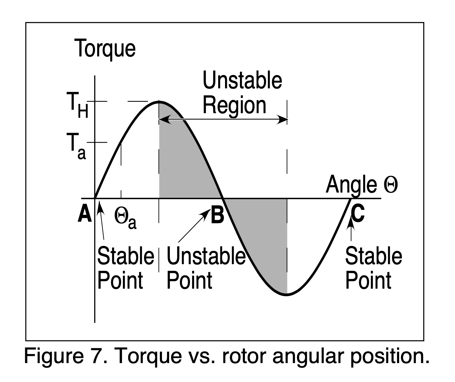
The further the stepper moves away from a given full step position the greater the restoring torque. When you start microstepping you end up pulsing between the two closest full step positions, this gives an asymmetric and variable torque depending on which side of the microstep target position the rotor is.
1 Like
This is making me think about those damned expensive but sexy drivers again… Just look at those stepper driver control modes! That servo control mode looks super interesting.
But I know I need to keep my mind away from the shiny electronics that’ll give me 40µm max and focus on the more impactful mechanics.
(Please give me an excuse to buy the shiny electronics)
1 Like
If you go servo you can no longer play the Imperial March on your CNC
There you go, saved you the money 
4 Likes
I was thinking about Nomad rigidity and it got me thinking: what would I do if I were to build a new CNC focused on rigidity that had similar constraints (weight, size) to the Nomad?
Inspired by the design philosophy from Vulcan Machining Co., I was thinking the basic overview would look something like this:
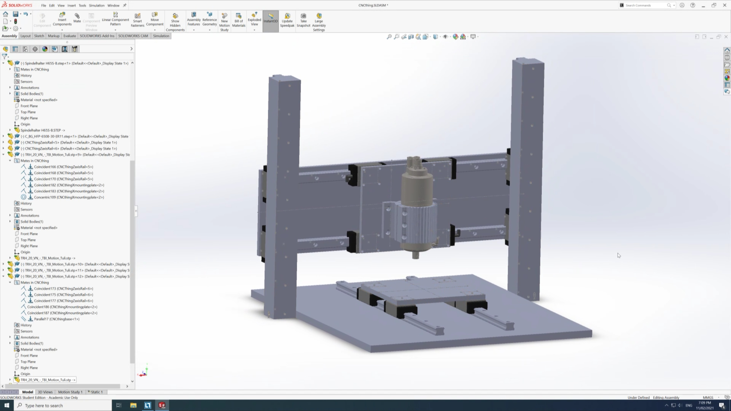
The interesting concept of theirs that I liked was that rather than mounting the Z-axis to the X-axis, they mounted the X-axis to the Z-axis. This gets rid of the lever effect you get when the spindle is low.
I don’t think I’ll take this any further but I thought it was interesting to contemplate.
1 Like
Hmm, I did a couple of test cuts to test accuracy:
- Faced the stock down to 15mm thick (from 18mm): 30000 RPM, 3600mm/min feed rate, 1mm DOC, 4mm WOC. No problems. Calipers and micrometer both show accurate to within ±40µm. Not fantastic but not too bad.
- Cut around the circumference of a rectangular piece of stock, 2mm DOC, ~3mm WOC, 3600mm/min. I cut so that it would be 94mm wide and 75mm deep. Calipers show 94.41mm wide and 75.41mm deep.
410µm seems a bit much. Any idea what could be going on there? I considered that it could be the steps/mm in my controller (currently set to 200, as I’m using the stock screws with 8mm lead with 8x microstepping) but that would lead to different results on X and Y due to different cut length.
Do the AB-nuts have that much flex? They can’t, right? I’d have seen it in the measurements.
Most vexing…
First time I ran generated G-code with the new spindle, it crashed directly into the stock and will no longer start or rotate by hand. RIP (for reference, this used to turn as easily as a fidget spinner).
I’ll write to Mechatron on Monday and hope there’s something easier than replacing the entire spindle…
Ouch,
Was it spinning or stopped when you crashed it?
It was spinning but when it crashed the VFD shut itself off. The endmill had embedded itself at least a good milimeter into the stock by then.
Perhaps a small portion of the 0.41mm might be attributable to the endmill itself?
If its diameter is slightly less than advertised then the magnitude of the difference would be doubled for the rectangle.
3 Likes