Nomadtron (Nomad + 800W Mechatron spindle)

This is a continuation of the saga started in this thread but I thought it was time for a new thread since it’s been quite a while since the original thread topic was discussed.

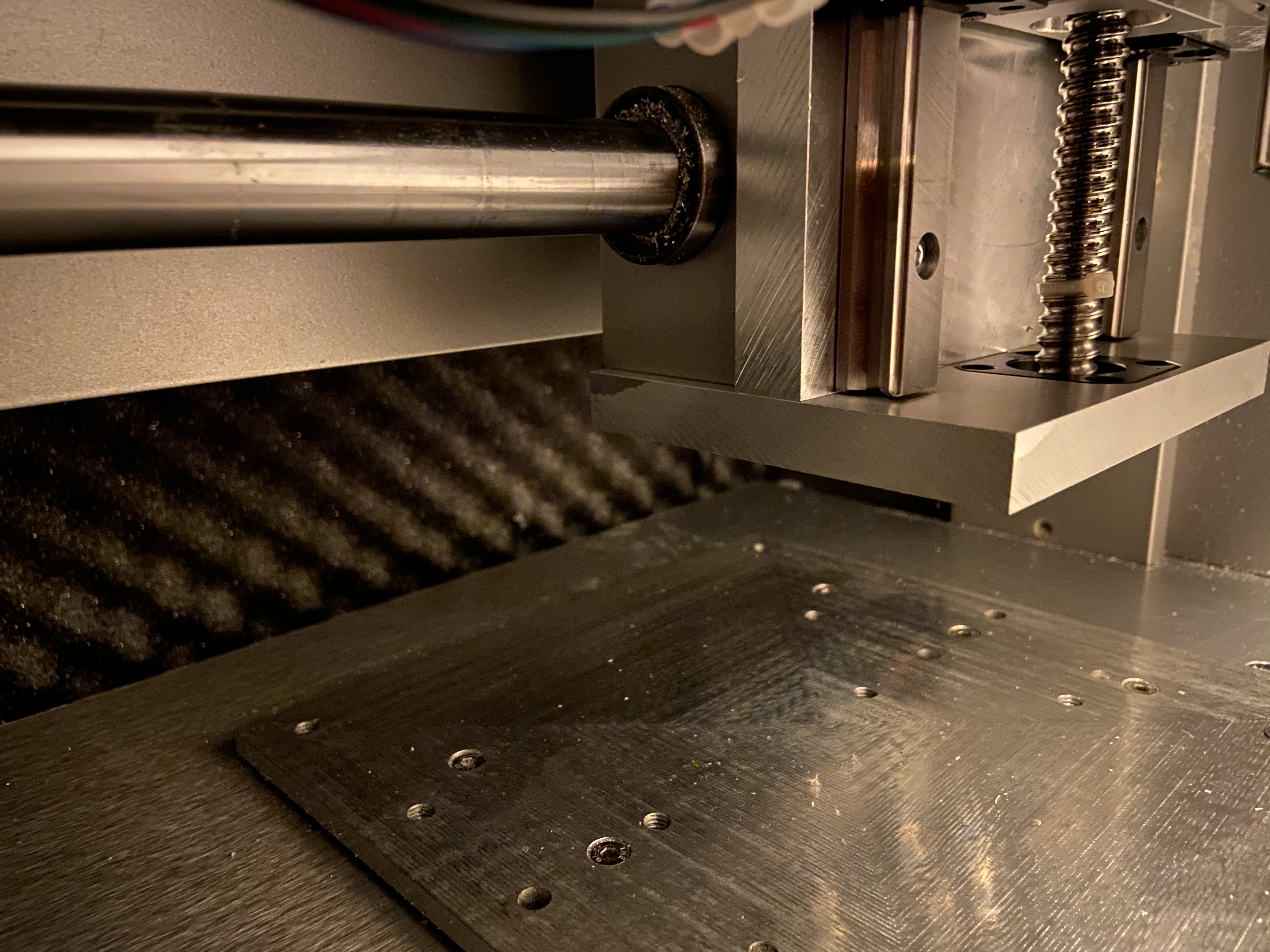
A quick recap of that massive thread for anyone who wasn’t following: After being disappointed in the Nomad 883 Pro’s inability to hog through Aluminium, I embarked on a quest to rebuild it better suited to my purposes. I’m starting with the Z-axis, which is based on TBI Motion ballscrews and linear rails. The new spindle is a Mechatron HFP-6508-30, which is a 65mm, 800W, 30k RPM spindle.

Here’s what the new Z-axis assembly looked like in CAD:

I got all the parts I ordered and after a long saga, managed to machine the Z-axis plate and assemble all the parts.

So, ladies and gentlemen, may I present my new Z-axis!

Short video.

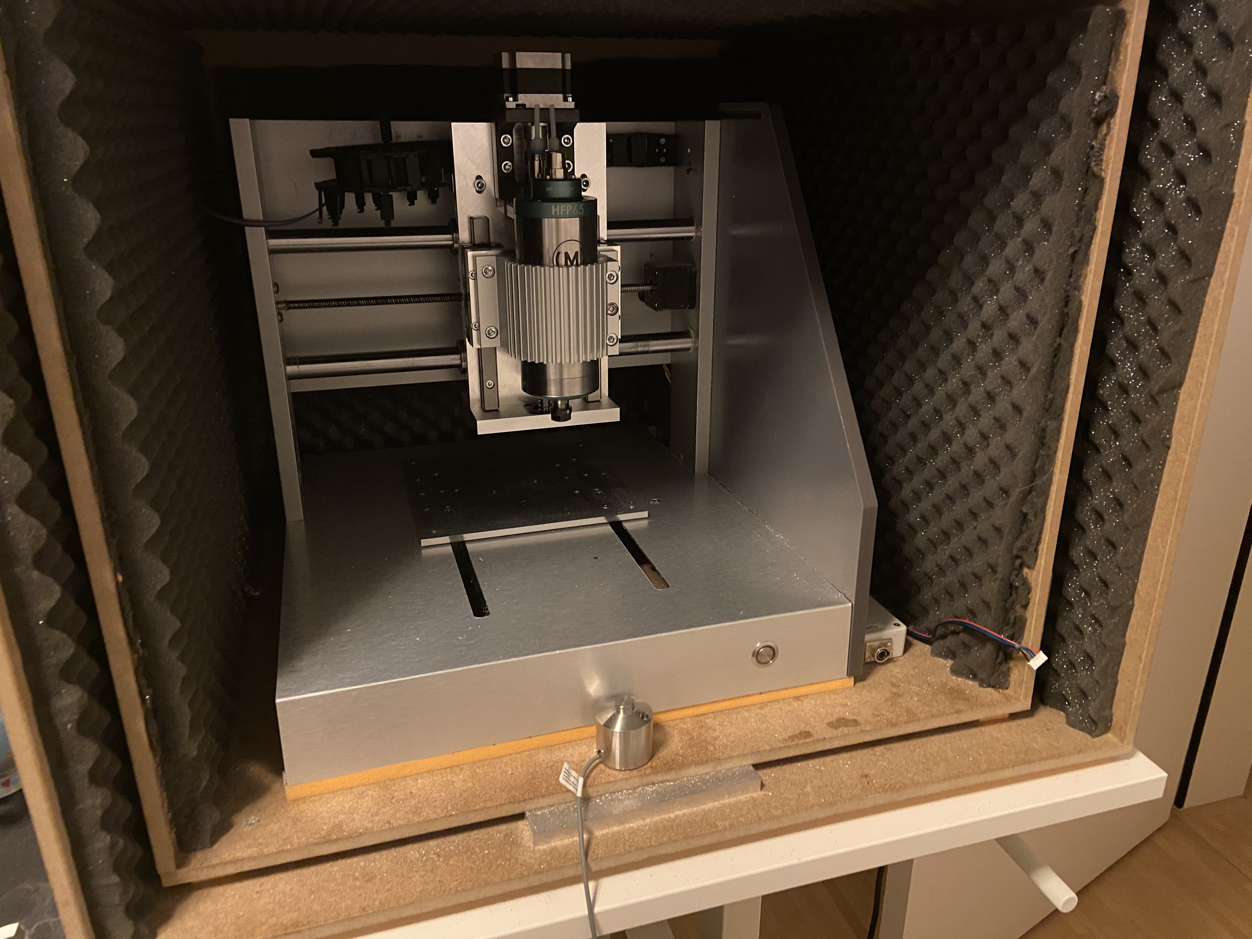
I think the Z-axis itself is a fairly straightforward design, all of the parts are off-the-shelf save for the backing plate, carriage plate and mounting plates. Those were all machined on the stockish Nomad and were simple apart from drilling holes into the end of the backing plate and a little bit of two-sided machining.

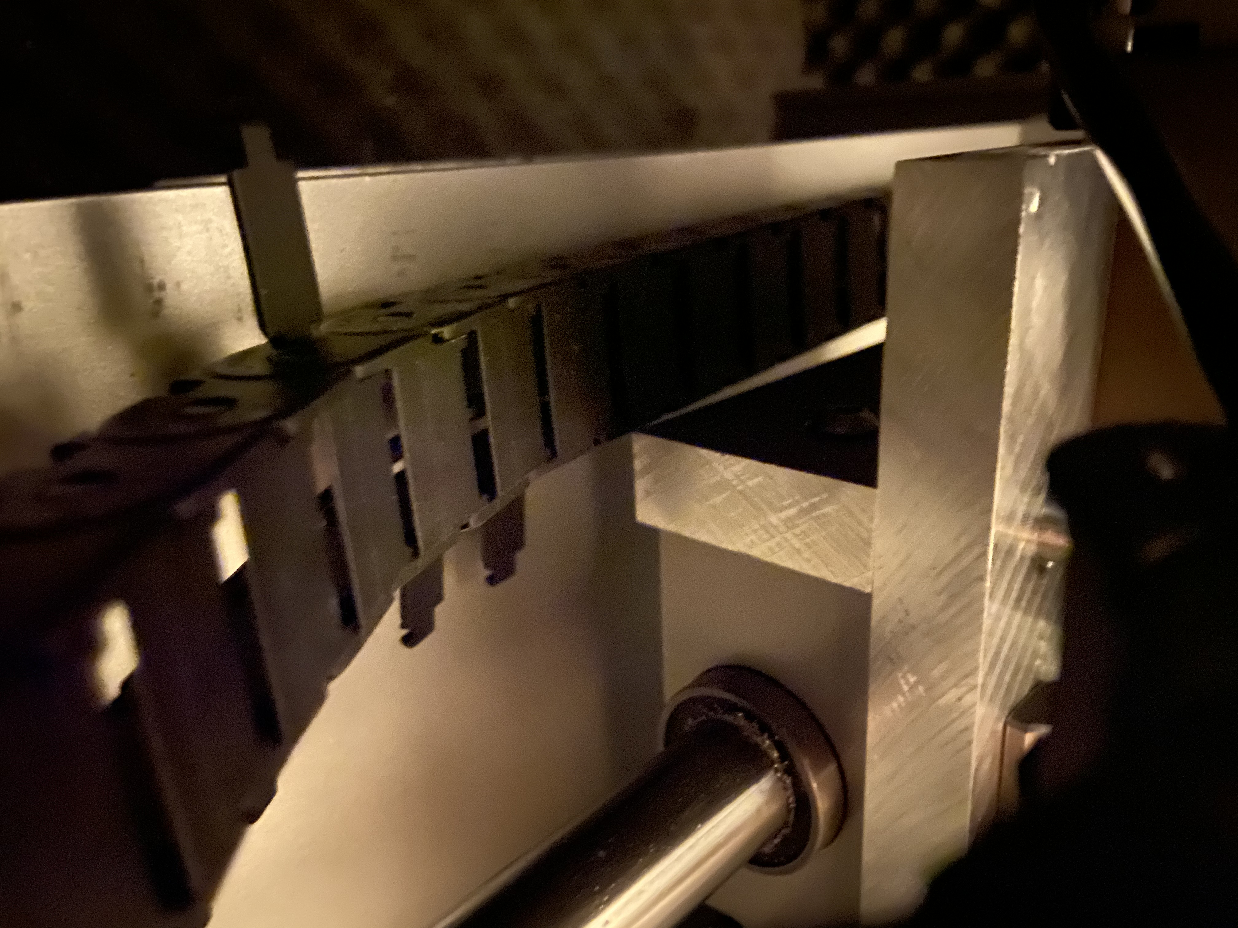
The part I’m most happy with is that this is a bolt-on addition to the stock Nomad. I even crimped the stepper motor cable to the same Molex connector the stock Nomad uses. Installation is completely non-destructive and utilizes the Nomad’s existing mounting holes:

The Z-axis itself was also fairly cheap, the materials cost $308.88 for the linear motion parts, 49.96€ for the Aluminium stock and maybe 20 CHF for all the screws and inserts and whatnot, so I think <$400 in total (excl. shipping) and you could do it even cheaper if you used unbranded rails and ballscrew. The biggest expense was the spindle and accompanying parts (VFD, cooling etc.), at ~2000€.

Anyhow, next step is wiring up the VFD. I’m thinking that at the same time, I might move all of the electronics out of the Nomad chassis and into a control box. That’s going to be a whole project in itself, so it’s probably going to be at least a few weeks until I can actually use the spindle.

Oh, I also need to install the limit switches…

9 Likes

That looks like the perfect size spindle, and 30k too! May I ask how much your z is offset to the front of the machine vs stock now?

The size was a huge component of why I chose that particular spindle. Plenty of power but not too heavy and not too tall.

And now that I’ve got a 65mm spindle holder, I can switch out the spindle for any other. If I get Mechatron’s HFP line, the cable is the same and apparently the VFD can be reprogrammed over MODBUS, so my CNC controller can do it. So swapping out spindles looks like it should be about as difficult as a tool change.

CAD tells me the distance from the backing plate to the spindle cone along the machine’s Y-axis is 96mm. Eyeballing the stock Z-axis with a ruler, that distance looks to be ~55mm, so the difference is somewhere around 40mm.

The 96mm is made up of:

  • Backing plate: 15mm
  • Rail assembly: 24mm
  • Rail/spindle block: 17mm
  • Spindle holder: 7.5mm
  • Spindle: 32.5mm

Unfortunately matching is nigh on impossible. Even if I drilled holes into the X-axis carriage to mount the rails and somehow bolted the spindle directly to the rails, I’d still have 32.5mm + 24mm = 56.5mm offset.

If it ends up being an issue, I think I’ll address it by replacing the X axis. There is room for improvement on Z but I think I’d have a much larger impact by replacing X.

2 Likes

Hello,
What are you using as cooling system for your Mechatron HFP?
Thanks
Y

I’m using their kit. I considered the chiller unit but I was afraid of the noise.

1 Like

Fantastic work, looks very promising! I’ll be eagerly awaiting some performance tests, I’m thinking of increasing the gear ratio of my VESC + 6354 longboard spindle to reach 20-30k RPM so seeing what yours can do will be inspiring for sure.

Getting very close to the first spinup of the spindle…

Remaining tasks are:

  • Wire 0-10V output from CNC controller to VFD (going to use some leftover ethernet cable I have laying around)
  • Connect enclosure fans to power supply (the 4 Noctua fans up the top there)
  • Connect water cooling radiator fans to power supply (elsewhere)

And at some point I’d like to connect the spindle’s thermistor to the VFD but I’m not entirely sure how to do that just yet, given that the VFD only has two logic ground terminals and both will be occupied.

5 Likes

Also decided to leak test the water cooling loop in the bathtub.

I have to say: WOW this is quiet. I can’t hear the pump over the near-silence of the bathroom.

I’ve got Noctua fans in the electrical cabinet, BeQuiet! fans on the radiator and the VFD doesn’t have a fan at all so I think the out-of-enclosure noise is going to be negligible.

2 Likes

Yep those Eheim pumps are pretty quiet. If it starts to clank a bit in a year or two it wants a new impeller and you can get them cheap on eBay.

3 Likes

IT LIVES

All the cuts looked to be full-engagement and RPM was 30000. The last cut was ~0.4mm DOC, 1500mm/min feed rate.

I think.

It’s been a long journey to get here and I was excited just to see if it cut after what feels like a year of figuring out which parts to use, designing the Aluminium parts to glue them together, buying them, assmembling them, buying the electronics, assembling the electronics without electrocuting myself, debugging the electronics… I didn’t pay much attention to correctly zeroing and I may still need to adjust the steps/mm for the Z-axis.

And I’m really happy with how quiet everything is. I was mildly concerned that the spindle would be louder or that the VFD would whine or something but the loudest thing in the room by far is the set of BeQuiet! fans on the radiator for the water loop. The spindle is a pleasant buzz from inside the enclosure, much more pleasant than the old Nomad spindle.

I’ll likely play with it some more tomorrow.

Another project I need to do before I go too crazy with it though is finding a solution (like a bigger enclosure) for the lack of space for the spindle power cable and coolant pipes. As-is, if the spindle is somewhat high, they drag along the ceiling of the enclosure or look like they’ll snag on stuff, which I really don’t like.

4 Likes

Okay, did a few more test cuts to get a feel for the spindle.

Best cut I was able to do in terms of MRR was ~5mm axial, 2.4mm radial, 30k RPM, 600mm/min with a 3-flute, 6mm Hartner endmill. Not very exciting to look at but here’s a clip.

IIRC, that’s over 7x the maximum MRR I was able to get out of the old spindle, so, uhh, looks like the upgrade worked?

The problem now looks like workholding. You can see in the video that the stock had lifted out of the vise. I’ll try again later with clamps on the T-slot bed or threaded table.

I also tried to do a rough stiffness measurement and got a maximum of ~0.1mm of movement when I pulled on a 6mm rod in the spindle, so the Z-axis did give some improvement there.

And finally, damn this spindle results in some nice surface finishes. I need to surface something with it.

4 Likes

Wow, that just sounds so smooooth. Well done!

1 Like

So it turns out I was babying the spindle too much. Using settings closer to the manufacturer recommendations, I was able to more than triple MRR again. I’m now at ~26x the maximum stock MRR.

Video

Cut parameters:

1 Like

Nice conversion but that last cut doesn’t look good at all. I’d stick to Vince’s recommendations and go with low DOC and high WOC. The amount of chatter you have is crazy and will kill your endmills in no time.

1 Like

Good point but the chatter, as far as I can tell, isn’t really related to the feeds and speeds. The same feeds and speeds that work just fine on the far right side of the stock start to chatter on the left side of the stock. This was the same with the stock spindle so I think there might be a mechanical issue with the machine (like some nut being more worn out on one side than the other).

My theories for the chatter are:

  • It happens in the middle of the X-axis, where the linear guides flex the most
  • It happens in between the Y-axis rails, where the most force is put on the anti-backlash nut

@Vince.Fab @spargeltarzan don’t suppose either of you have theories or opinions on my theories? Vince, could this be what you were talking about regarding the AB-nuts?

Have you done any maintenance on the AB-nuts recently? I filled my X-axis nut up with grease the other day and saw a massive improvement from ~0.5mm to unnoticeable by eye (very scientific™) movement when pushing on the axis by hand. This is before: https://photos.app.goo.gl/yxdqUNyxJHyqJVhu9

Another though: Could it be that you are overpowering the AB-nut springs, since you’ve now got the spindle power to put a lot more force on the axis?

2 Likes

Good idea but I think I’m just going to try to take it easy on X and Y for now.

Thinking about it some more and after discussing it with a friend, I think I need to replace the X and Y leadscrews with ballscrews.

Vince has already pointed to the AB-nuts as a problem when he did his spindle upgrade, so I think the chances are fairly high that I’m running into the same issues he did.

A friend also pointed out that the Nomad doesn’t look mechanically ready for this. The leadscrew is fairly wimpy and it looks unsupported, all the cutting force is applied axially to the stepper motors, which is usually pretty bad for them. Vince’s teardown shows what might be axial bearings but it’s hard to be sure.

Vince has shown that putting ballscrews on X and Y isn’t too big a hassle and now that I’ve done a ballscrew on Z, I’m feeling a bit better about doing it on X and Y.

2 Likes

I would get comfy with and indicator and check everything, see whats really going on.

No matter what mods are done, you’ll always be able to overpower the sprung nut. When converting to the ballscrews for X/Y and leaving the Z leadscrew, the difference in movement was painfully obvious.

Integrated screw Nema steppers have a little different bearing arrangement than non captured. Even when roughing heavy, you’ll unlikely see enough force to really make a difference BUT…everything worth doing it worth doing overboard. Right?

The space the Nema 17s currently occupy would make for a nice spot for ballscrew bearing assemblies. Then just drill through the frame and outside mount Nema 23s with isolation couplers!

1 Like

Is there anything in particular you’d check?

I like the idea but need to think more about the specifics. I might need to make a custom ballscrew bearing assembly and get some unusual machining done to the ballscrew to make that plan work…