PLA will dissolve in Acetone, I’d do a sacrificial mount which the sensor screws into. Or use PETG which doesn’t respond to Acetone.
Ideally, yes, but time axis noise in your sampling effectively reduces your highest effective frequency and amplitude readings are a bit iffy right up at the limit so, yes somewhere between 1k and 2k will be good. That’s enough for these experiments anyway.
I would expect the machine resonances to be visible in both cut and spindle & collet tests. There’s only the machine to resonate in the spindle & collet tests so modes found here should also appear in the cutting tests but those may excite things more violently and also produce frequencies from the cut, workpiece etc.
Depends what you’re looking to achieve, if you want a lobe-stability plot for frequencies to avoid then, yes, spindle data is probably enough. If you’re asking where the highest reward fixes are then it may be worth probing the machine a little too. As Gerry says, the Y supports and X rails are an open parallelogram which might benefit from some cross bracing.
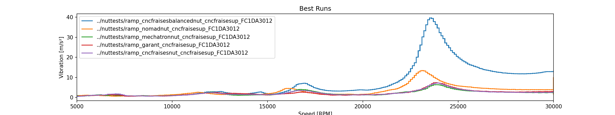
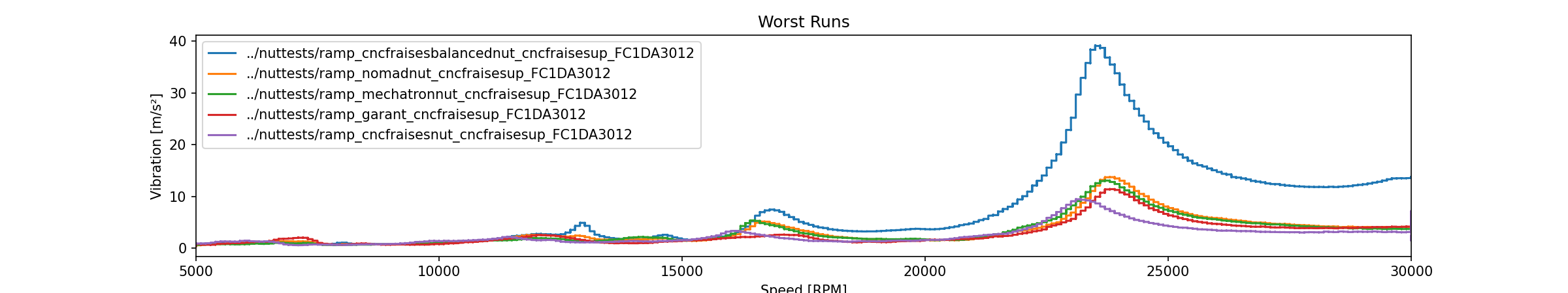
That collet I didn’t include earlier is a sample I was sent from CncFraises that they don’t yet sell but were interested to have tested. It seems to perform the best of all the 1/8" compatible collets I’ve tested so I’ll happily recommend it to European folks when it’s put in the shop.
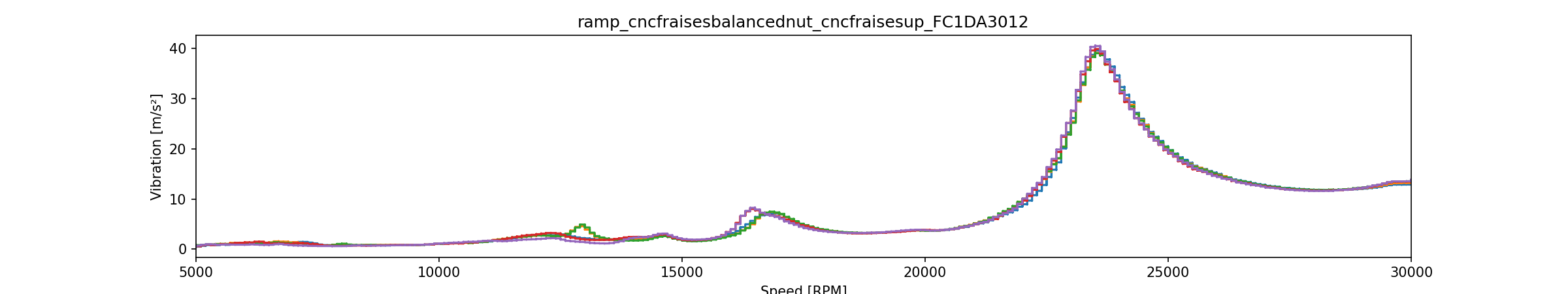
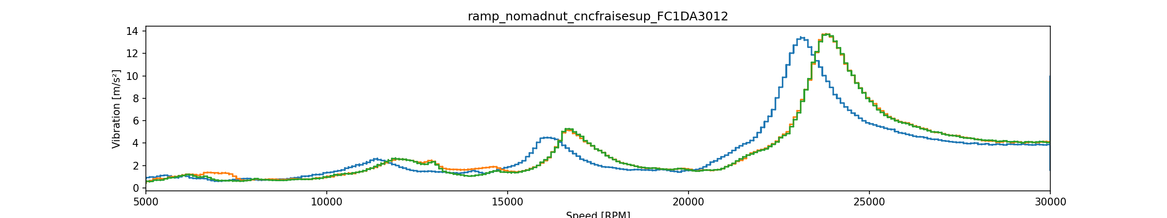
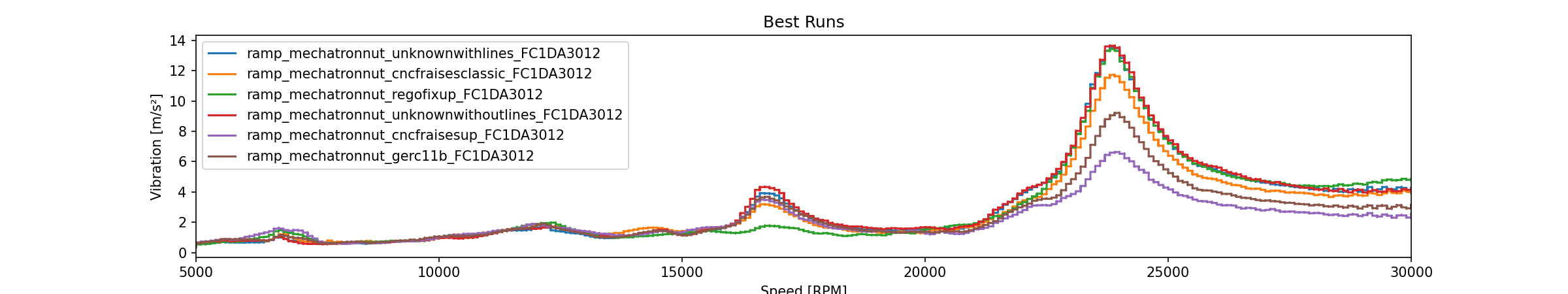
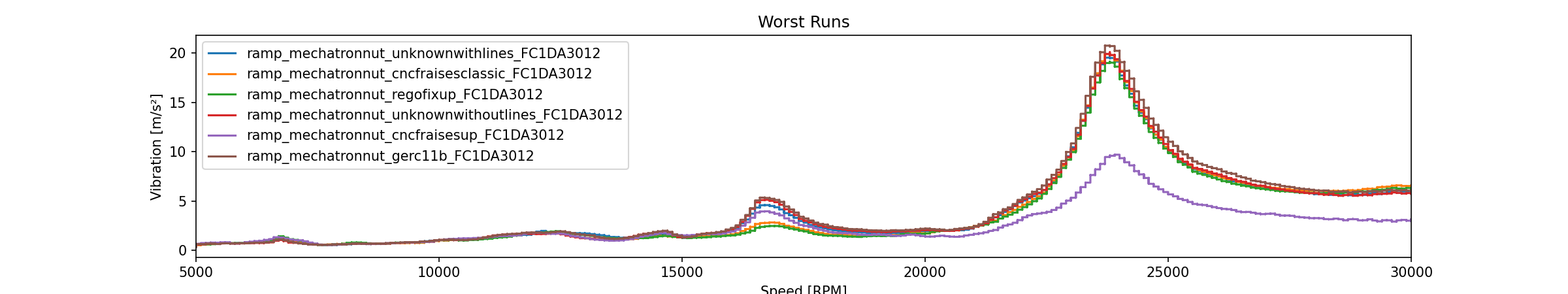
However they also sent me a not-so-great sample “balanced” ER11-A nut (first chart on this post). Seems there might be some kinks to work out in production because it performs by far the worst of all the nuts I have on hand. It’s also the most consistent nut but I don’t think that’s a good thing in this case
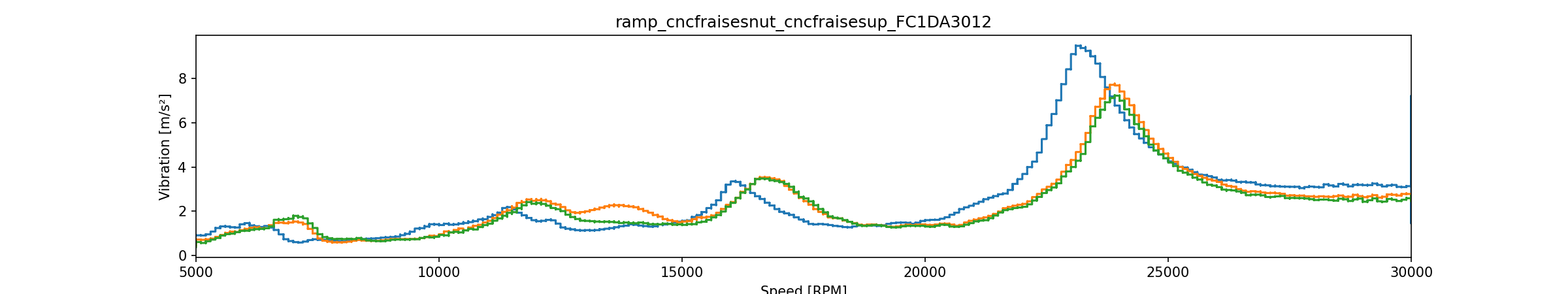
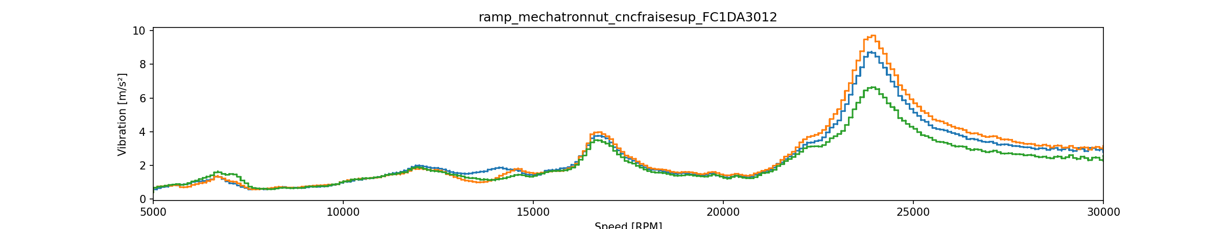
Their other nut is in second place behind the Mechatron nut though.
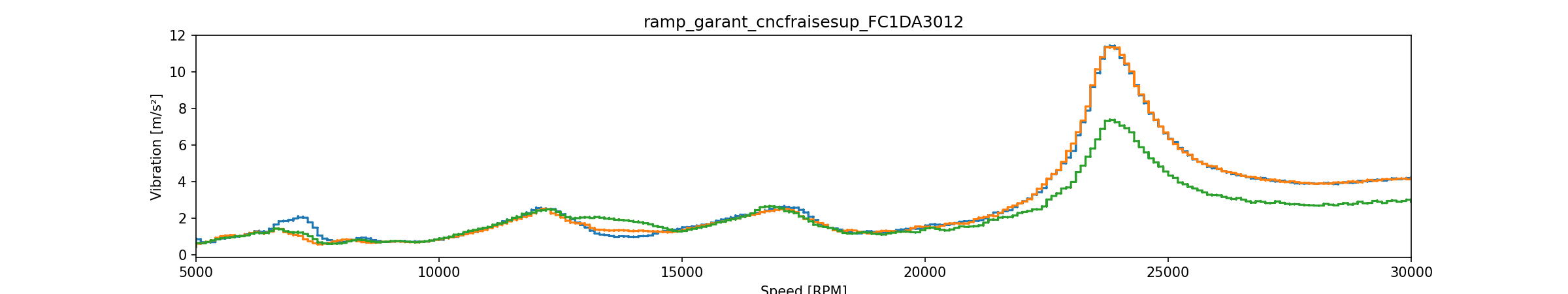
I was also impressed that the Nomad nut did so well, about as good as the Garant nut, which is rated up to 24k RPM.
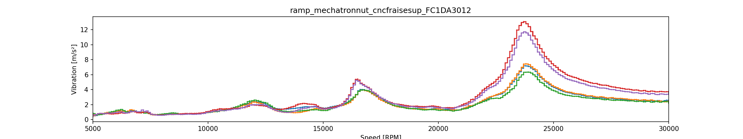
For now though, I’ll stick with the Mechatron nut. At some point I’d like to test one of the high-speed nuts from REGO-FIX like this one though…
That is all consistent with the Y,Z coupled deflection being a rotation about the X rails. As the collet applies force in the horizontal plane this excites three dimensional modes of vibration in the machine. If you look at the pivot arm from the mass center of the spindle to the center of the X rails you may find that the Z distance is longer than the Y.
On the topic of the collet tests showing different amplitudes when done up each time, all four major parts will have some imbalance, the spindle, the collet and the collet nut and then the cutter in the slightly off-center of the collet. There’s more but you get the point…
When composed together as a system these produce one effective imbalance which is the vector combination of each of the parts. If the collet is rotating a little each time you tighten it up then you’re producing a different net balance error each time.
Yes! Adding more metal is always a satisfying way to fix things
I saw a picture of the older Nomad 883 and noticed a different support structure for the base of the X axis support rails compared to the Nomad 883 Pro:
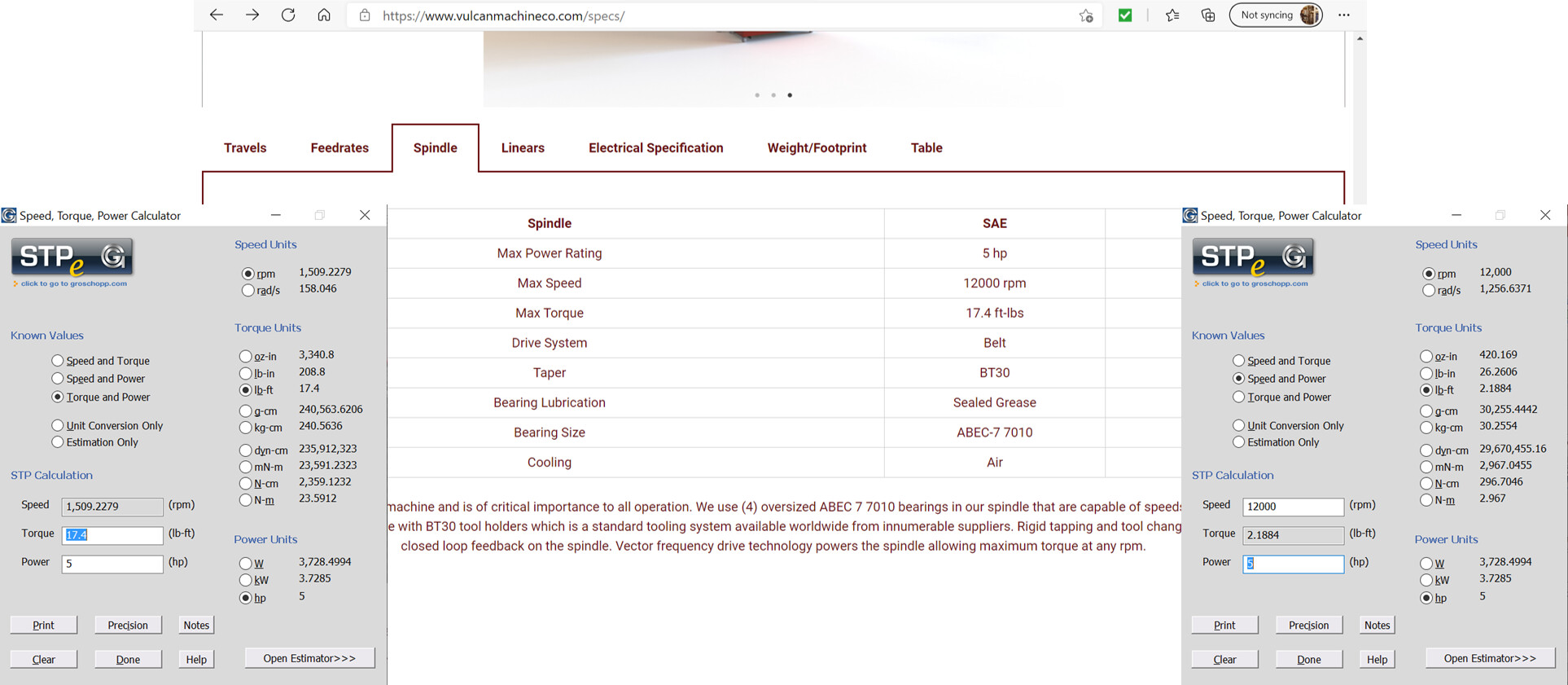
I found Vulcan Machine Co’s design theory very interesting so I’m thinking of building a machine that has the X-axis mounted to the Z-axis rather than the Z-axis mounted to the X-axis. This should keep the spindle nose much closer to the physical “sweet spot” of the machine and remove most of the levering going on, which should make an otherwise very light machine less jelly-like.
On the other hand, I could just replace the Nomad’s X-axis with a ballscrew and linear rails, that would be substantially less effort.
An interesting design. Those two axes are a little like a Shapeoko with the spindle rotated 90 degrees.
For these smaller machines, I’ve sometimes wondered if it’s possible to have the moderately heavy spindle in a fixed position, and move the table in two or three dimensions instead. There’s rarely anything heavy on there.
Like they say “The spindle is considered the heart of the machine. It is arguably the most critical component in the entire machine and thus something we took extra seriously when designing our mill.”
Going back to “how might I fix my machine”, I spoke to a friend who raised a very good point: though I see rotation in X and vibraton in Z, indicating that the machine is rotating around the X-axis, that’s not enough to conclude that the X-axis is the problem.
My assumption was that there’s enough slack, wear or general rubberiness in the X-axis rods that allows the spindle to move somewhat freely.
However it could be, for example, that the cutting force is putting energy into the ABN springs that are then discharging the energy back into the endmill, causing higher forces on the spindle than would be normal.
I should be able to test this by putting an accelerometer on the bed. If there’s flex in the X-axis, the bed should remain somewhat stationary. If there are issues with the Y-axis ABN, the bed should also move.
Your friend is quite right, measuring things to check and test assumptions before doing work based on those assumptions is almost always a good plan.
I found many unexpected and initally unexplained things when measuring where the deflections on the Shapeoko were coming from. Each time I thought I had a coherent model I’d find one or more measurements that didn’t fit the model’s predictions and have to go back, measure and think again.
Despite my undying need to upgrade my machine, I’ve decided not to try to upgrade the X and Y axes for now, instead I should try actually making some stuff (gasp).
But I do still want to take a data-driven approach to feeds, speeds and tooling, so I want to run tests.
And on that subject, I’ve been thinking about how to test endmills. I see a couple of things I want to measure:
“Smoothness” - how easily the endmill cuts through the material. I’m thinking that the magnitude of vibration according to the accelerometer should provide this.
Surface finish - I can use some kind of magnifying device to inspect the quality of the cut surface. This could be a microscope or a macro camera lens (probably more likely the latter).
Tool wear - This is the hardest one for me. I don’t want to destroy the endmills because I want to use them and some of them are expensive. But if I cut with them normally, will any wear even be visible?
And then there are questions about how to set up the cuts. For one endmill diameter, it’s easy: use the same chipload, width and depth for all the cuts. But what do I do if I’m testing both 3mm and 6mm endmills?
What I’m thinking at the moment is to fix the width of cut as a percentage of the tool diameter and to vary the depth of cut to compensate. E.g. if I double the tool diameter, I double the width but halve the depth.
I have mixed feelings about generating test data using test scenarios (I have the same feelings when writing unit tests). You can end up generating result data that is mostly useful for tests but often is only partially useful outside of the tests. We tend not to make tests as complicated as non-tests because we want to collect small and clean samples of data.
A slightly different approach would be to collect data whilst making things you intend to make. This would then incorporate the runtime for a typical job, the topology of the cuts, the change in temperature of the endmill and machine, etc, in case these effect the overall performance. The disadvantage is the the data will be temporally complex and hard to process.
That said:
Smoothness is a good one and I’d be interested in these results. But be sure to include paths not only in X and Y but diagonals, since my Nomad can scream when going diagonally.
Surface finish… I think this is hard to establish since the visual finish might be a misleading metric for some materials. The reflectiveness of the material will yield different perceptions of quality.
Tool wear… the third thing in your couple of things (:)) might be measurable by the change in the width/accuracy of the cuts you make. But I think you might also want to consider adding temperature as a measured item, either with a conductive or thermal temperature sensor. The idea is that dull tools might run hotter.
I get the points you’re making and I’m under no illusions my endmill tests will be 100% applicable to real-world programs (the G-code kind) but I’m not sure how else to do it. To measure the performance of the endmill, I have to fix all the other variables, there’s not really any way around it.
Your suggested approach would work great in a proper machine shop where you need to churn out tons of parts (just swap out the endmill between each run and run a full job) but for me, the parts I make are usually unique, so there’s no useful comparison that can be made between two runs with different tools. I could collect tons of data but it’s not useful when I have this gigantic uncontrolled variable running around.
And for the other suggestions:
Smoothness: decent point, my Nomad has difficulties cutting along X, but would should we expect the endmill to make a difference?
Finish: I’m only cutting Aluminium, do you think we need to worry there?
Wear: would you expect the width/accuracy to vary over one or two short cuts though? And where would the temperature sensor be attached? To the tool? Spindle?