But I’m still able to see a second harmonic at 1kHz, why is that?
I basically just memcpy’d floats to a file, primitive but works
Hmm, that’s an interesting idea. I could set up a small rounded-square pocket and do a grid on top of a piece of stock, with one pocket per endmill. I could even make the rounded squares of a size to be useful (e.g. endmill holders) so I’m not wasting stock.
Makes the toolpaths a bit different for 6mm and 3mm though…
The filter attenuates high-frequency content in a gradual manner. The attenuation is 3 dB (50%) at 1209 Hz, which means that amplitudes for frequencies below but near 1200 Hz are pushed down somewhat as well - but of course less than 3 dB. I was aiming at the fact that amplitudes for frequencies above about half-bandwidth are not particularly accurate (attenuated), not that they disappear. The filter affects phase much worse, by the way.
Actually, round pockets would perhaps be useful if there were some sort of timestamp, because direction would change continuously and effective feed would gradually decrease as the pocket diameter/toolpath radius increases.
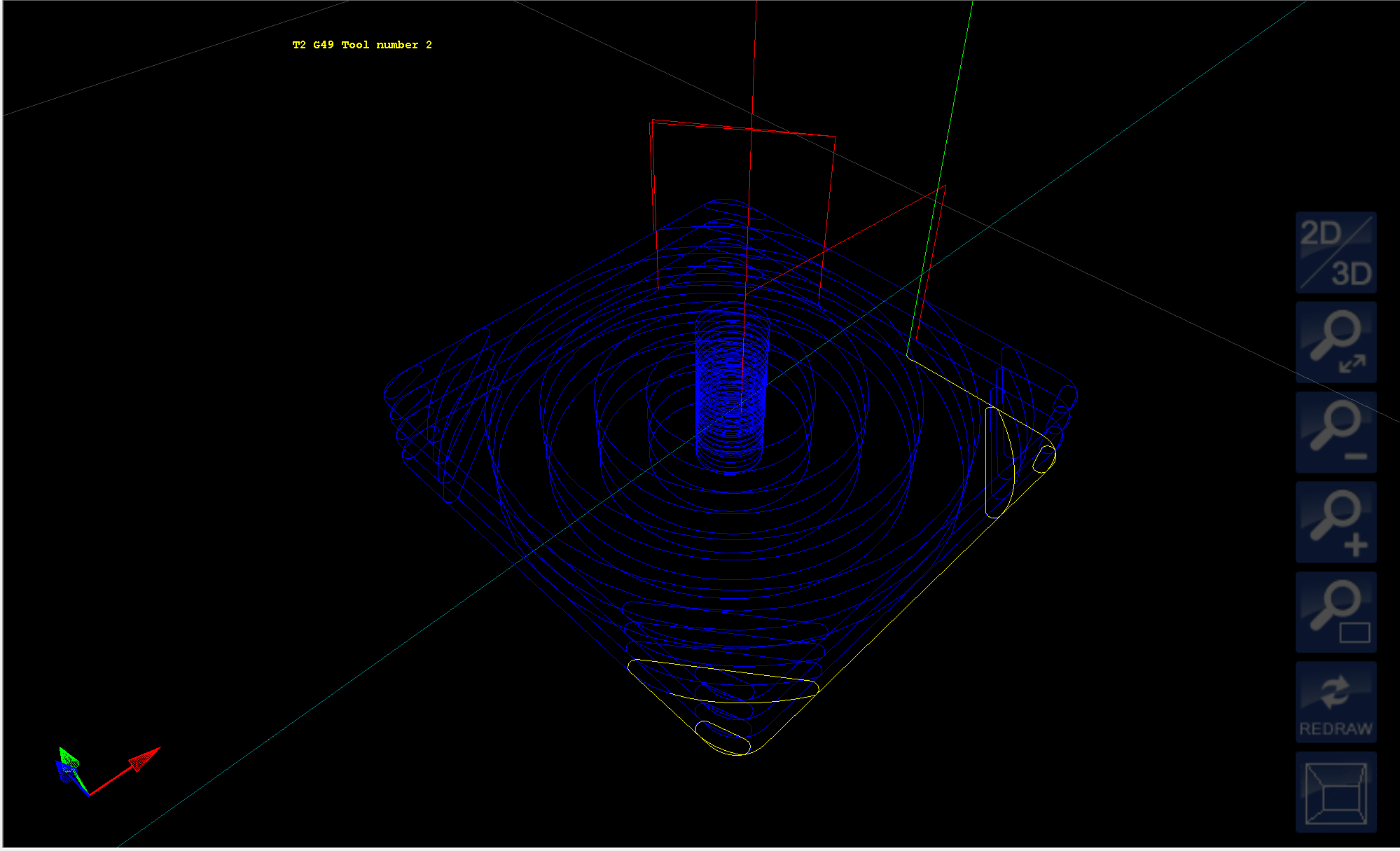
The spiral motion of an adaptive clear is quite informative on the Shapeoko, constant engagement and varying angle, as it runs round the path you get to hear the different vibration modes triggered by the different load directions.
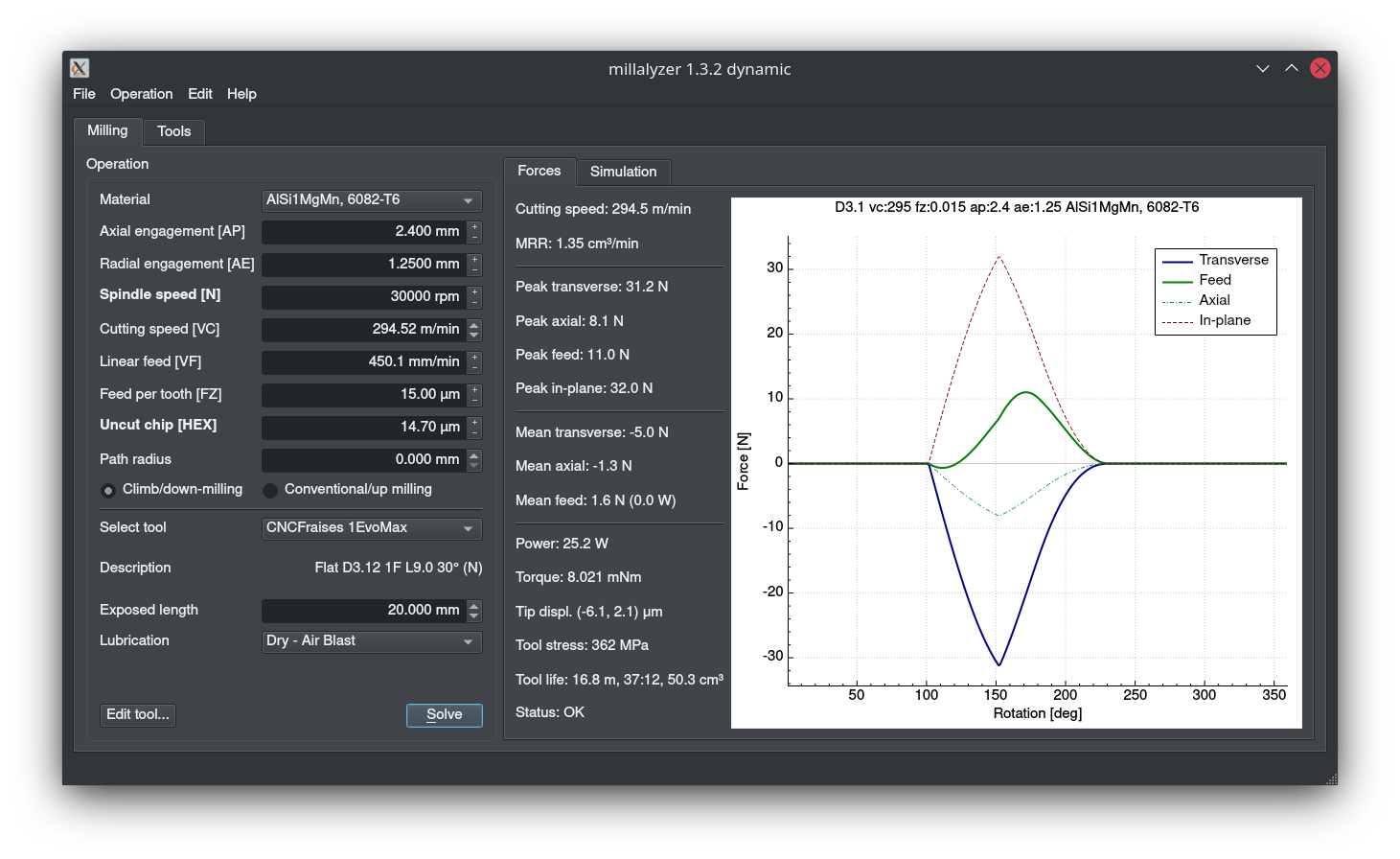
I did a couple of test runs with 1/8" endmills using an adaptive toolpath at 30kRPM, 1.25mm axial, 2.4mm optimal load and 0.015mm chipload (450mm/min).
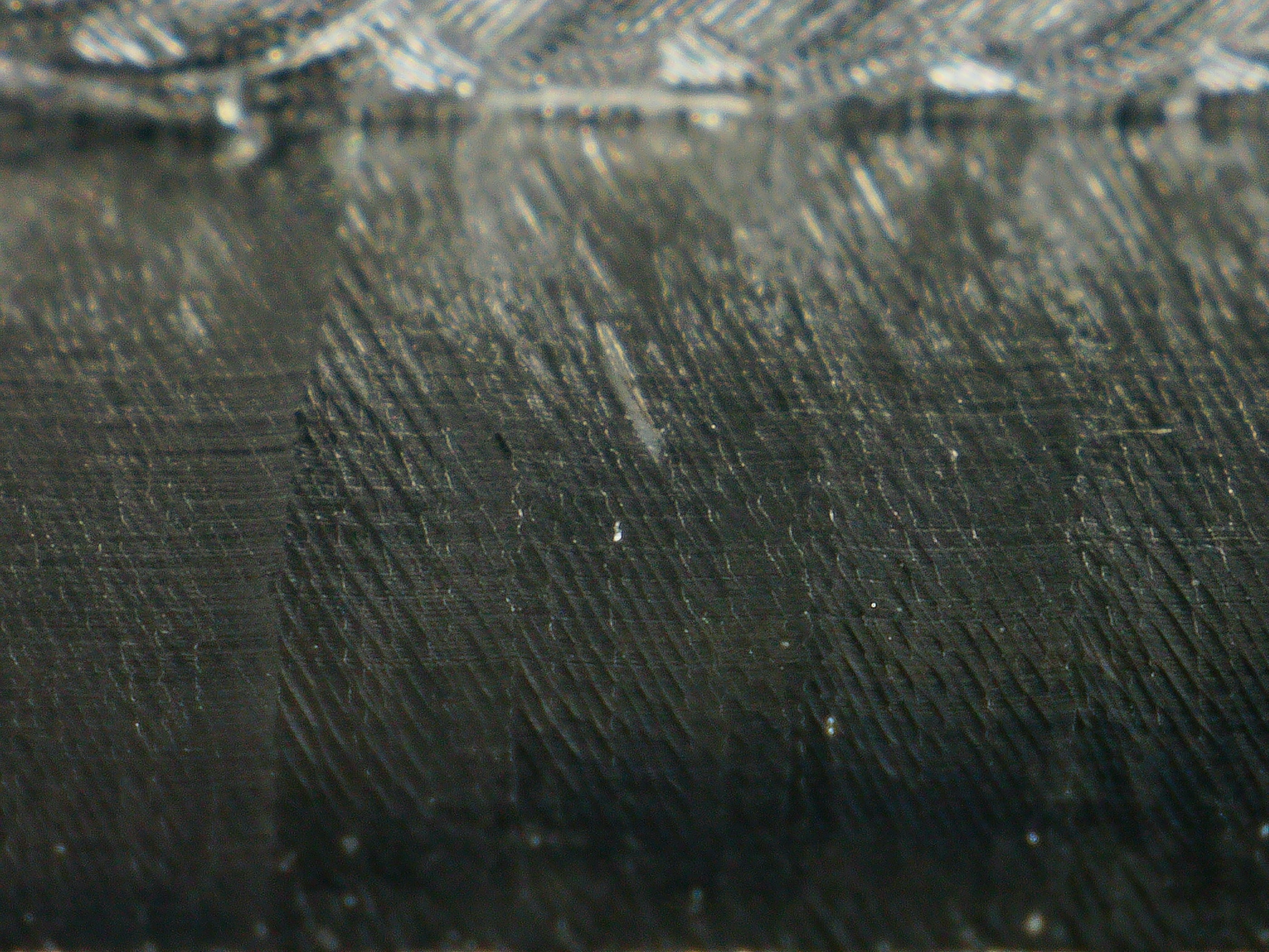
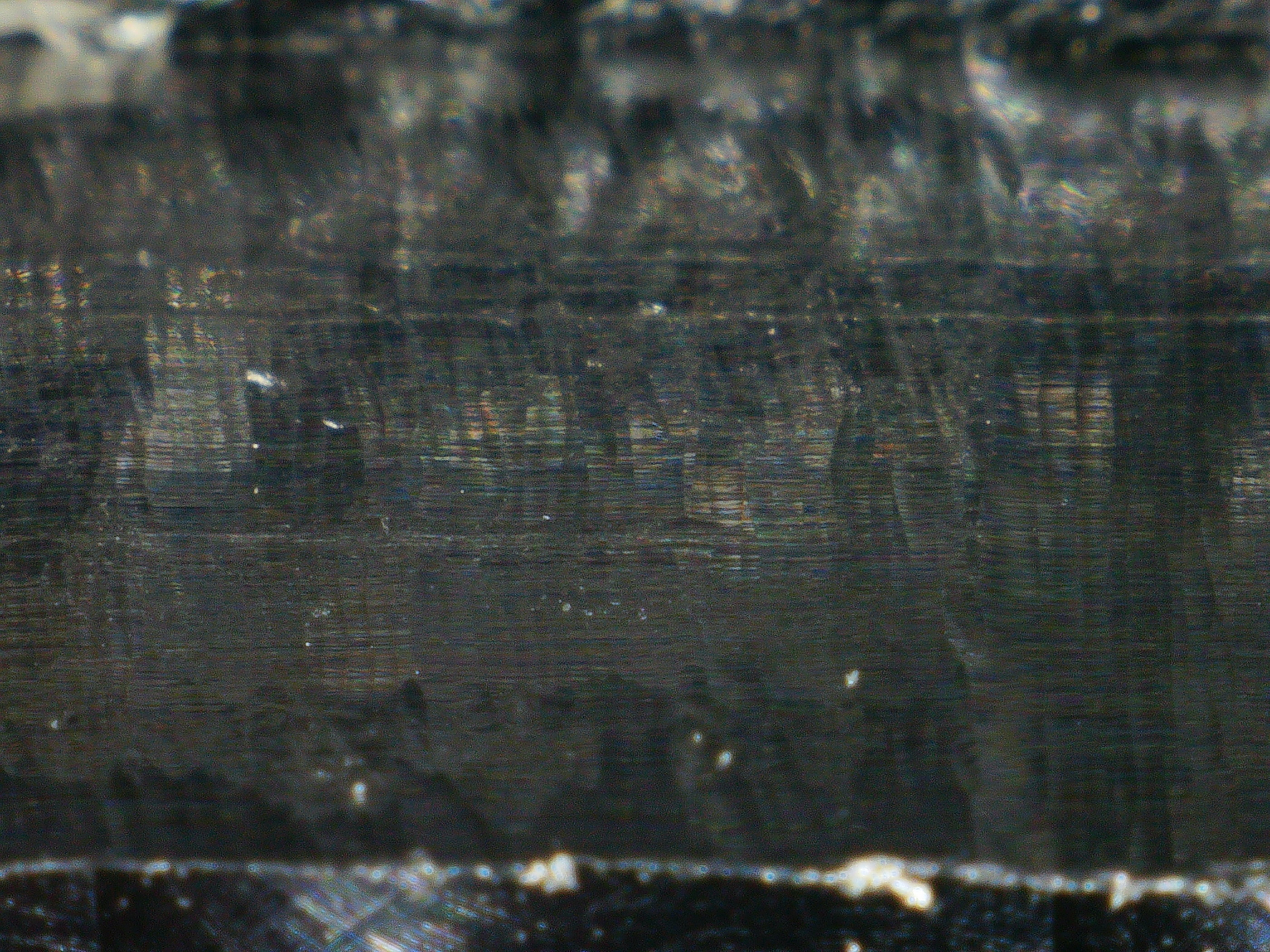
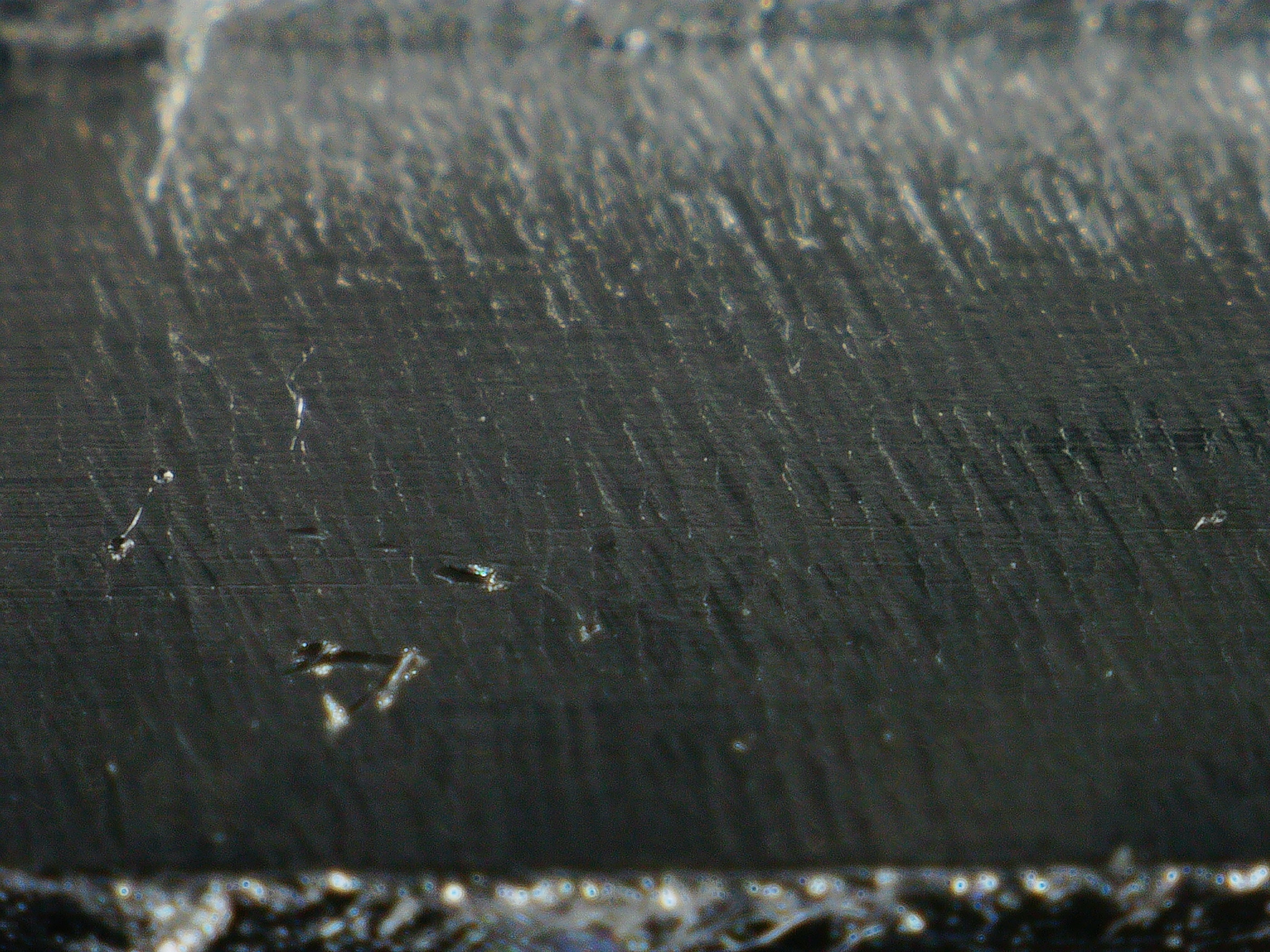
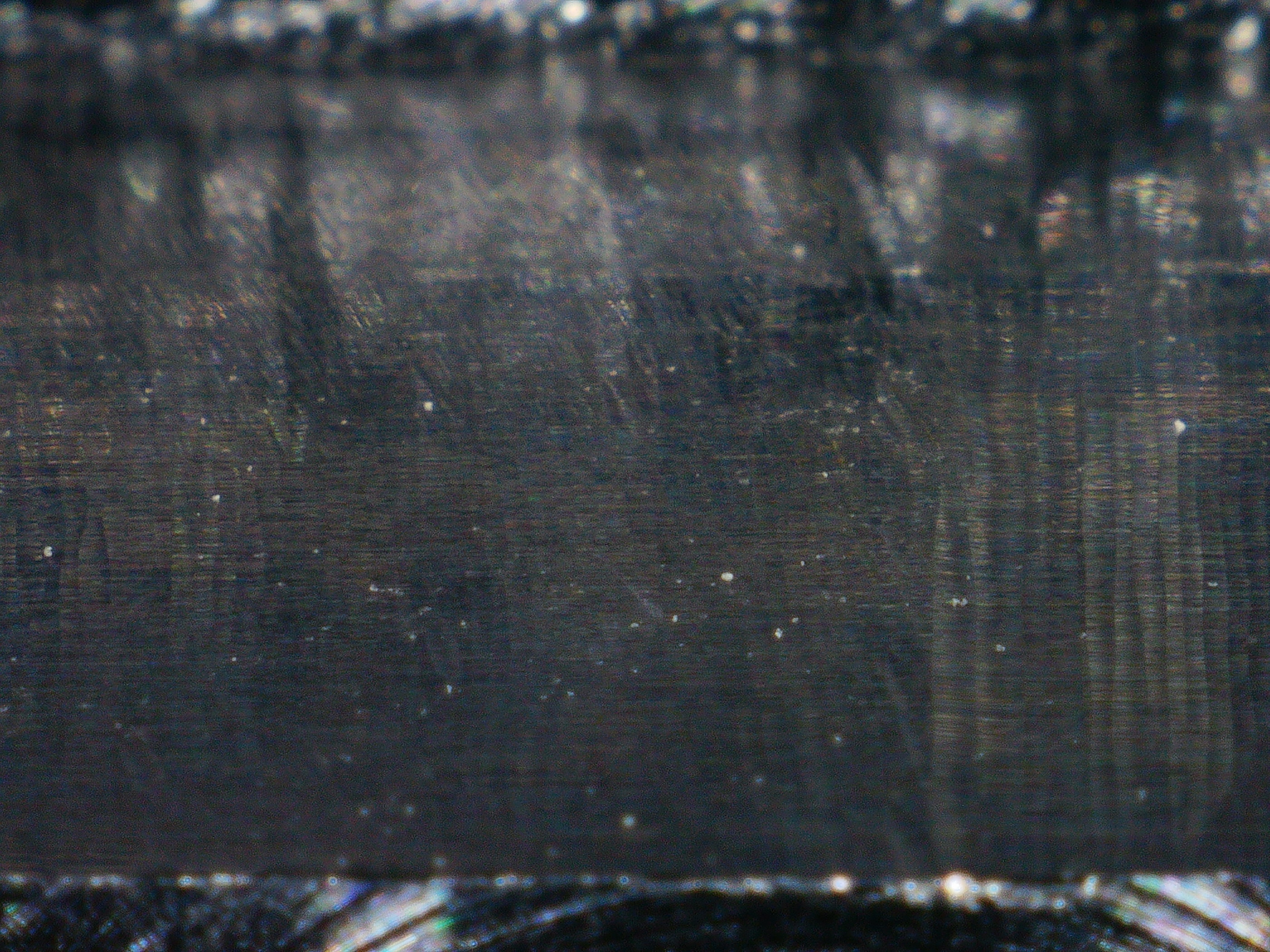
Unfortunately after I finished, I found out that I had no vibration data but at least I got to play with my new microscope. I bought a cheapish Chinese digital microscope and used it to inspect the endmills and the milled surfaces.
I don’t think it really shows in the microscope images but one really interesting thing was that the pocket for the EVO MAX endmill was visibly more reflective than for the other one.
I got my accelerometer data collection working again and was looking at DATRON feeds and speeds for some reason and decided to try a high-ap, low-ae cut again.
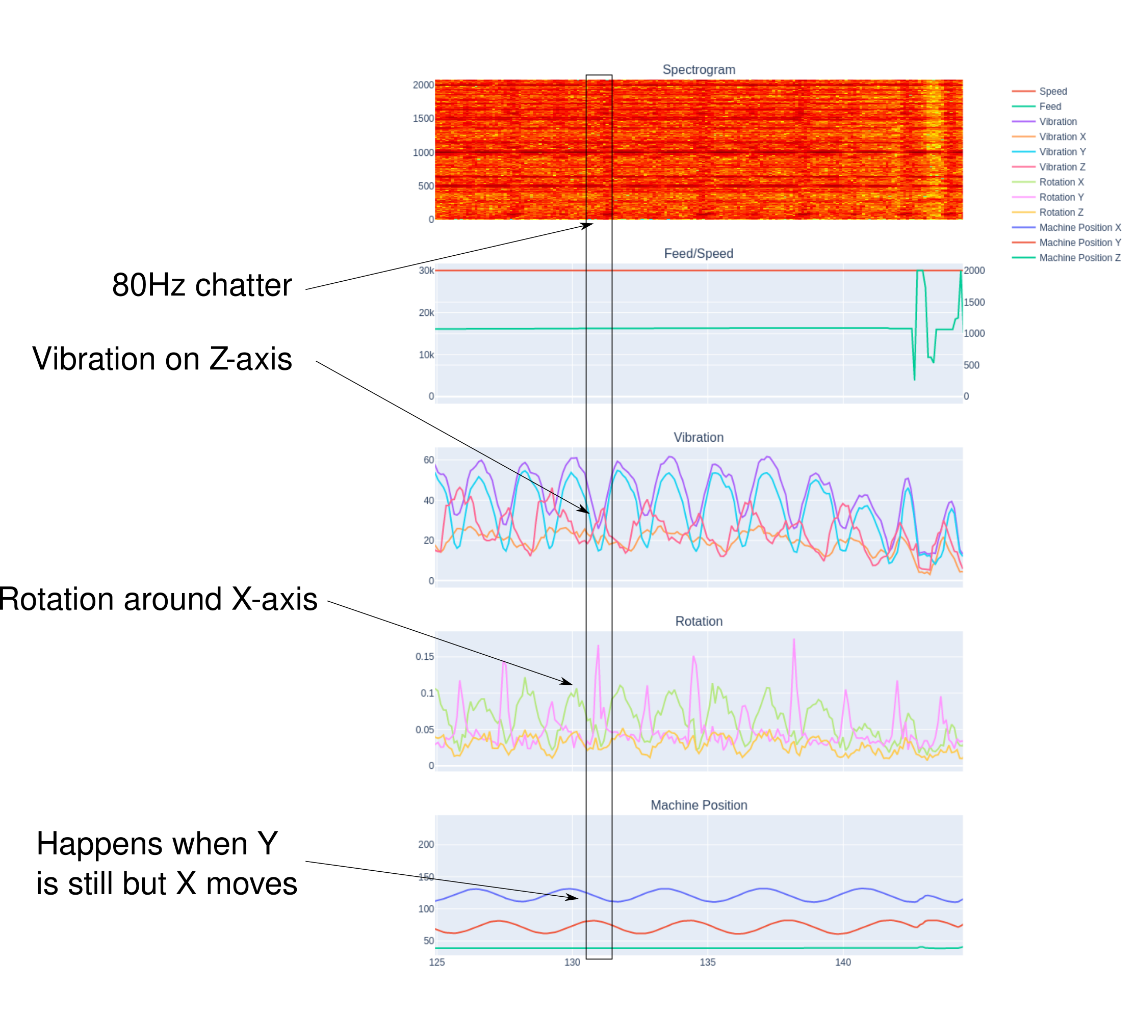
This is just moving from right to left along X, as usual, 8mm ap, 0.3mm ae: Readings
It sounds really unpleasant when that vibration around 80Hz starts but the chips are so nice and the MRR is twice as high as that cut above…
I wondered if I should bother pursuing this more before I start my tests or if I should just settle with high-ae cuts and leave it at that. Then I decided to just test two pockets and see what would happen:
These toolpaths are both very similar to the one above. The only major differences are the parameters and the fact that I generated it with Solidworks VoluMill instead of HSMWorks 2D Adaptive.
@LiamN’s point about the spiral turned out to be pretty spot-on, it revealed that there’s a pretty narrow angle in which I see issues, aside from that the cut was reasonably smooth:
A little reading suggests that it’s more usual in a mechanical system to excite the resonance with a subharmonic (I was thinking acoustic resonances which like the multiples).
Anyway, because 83Hz is 1/6 of 500Hz, in a high-Q resonance it’s possible that you’re exciting it with the spindle frequency as the interaction between the cutter and the workpiece builds up. It was pointed out to me (by spargeltarzan I believe) that the size of the chip on the next rotation depends on the deflection in this rotation so you can create subharmonics of the spindle frequency. Once the resonance has started it will just keep on going.
It’s worth a try moving off to a tooth frequency that is not a even harmonic of the main resonance, might not work but it’s an easy experiment. I have found my Shapeoko responds strongly to this.
Hmm, do you have a concrete proposal? For a second I thought maybe ‘500-(83/2)’ but if the harmonic is at 1/6 and I decrease the frequency, won’t the harmonic just move with it, to 76Hz?
450Hz ? That would be 27kRPM for the spindle I think. If it still resonates there then I’m talking rubbish as that would be about 5.4 times the 80-83Hz resonance.
Looking back up at your previous data it seems there was a strong resonance mode at 24k when testing the spindle nuts which would be about 400Hz so best stay away from there.
Okay, put it at 27k RPM and it looks like a definite improvement. Results.
There was still a little bit of vibration around 80-90Hz but this time it only really seemed to happen when moving along the Y axis and only on the right hand side of the pocket, not the left. I speculated that it could be because my air nozzle is pointing at the endmill from the bottom right corner, and it’s slightly more right than it is bottom, so it could be chip clearing, as it would be difficult for the nozzle to get air in there.
So I decided to test it again but after moving the nozzle to be positioned towards the bottom. Results.
That also left me confused, as now the vibration had moved to the top of the pocket but not the bottom (and the bottom is what I would have most expected if chip clearing was the issue.
So I ran it again, this time with the nozzle pointing from the bottom left towards the endmill. Results. Same result, vibration along the top of the pocket, so I think nozzle placement isn’t the problem.
Then I moved it back over to the right side of the machine, leaving the nozzle as it was. Results. Once again, vibration seemed to be on the right edge of the pocket.
So I feel thoroughly confused but the vibration seems to have something to do with the position.
Anyhow, the vibration no longer seems too substantial as long as I’m doing dynamic tool paths, so I think I might try to continue using them. The machine seems to survive so worst case, I break a few endmills.
It sounds like you’ve found a spindle frequency that’s less effective at exciting the major vibration mode(s) of the machine which is good.
As for different vibrations at different positions on the machine, that’s exactly what I see on the Shapeoko and what my simple models suggest. The effective stiffness of your X rails for example, changes rapidly as you move from the center towards either end. Are you seeing more vibration when the Z carriage or the Y carriage are towards the middle of their stroke and furthest from solid supports?
And just to make you feel better, my 2.2kW high quality Chinese spindle has started to make an awful screeching sound thanks to the ‘lubricant’ in the bearings all going dry and crunchy. I’ve had to try to squirt new grease into them to keep it going now.
Fortunately some helpful person has put a video on YT of exactly this problem (beware the horrible noise at the beginning which is what I heard when I shut off the dust extraction)
Although his spindle seems to have two fewer bearings than mine which are, amusingly, marked for alignment like proper SKF angular contact bearings would be.
Ugh, so I spent an hour this morning testing 10 endmills but when I came to analyze the data, turns out the accelerometer had written all zeroes for some reason
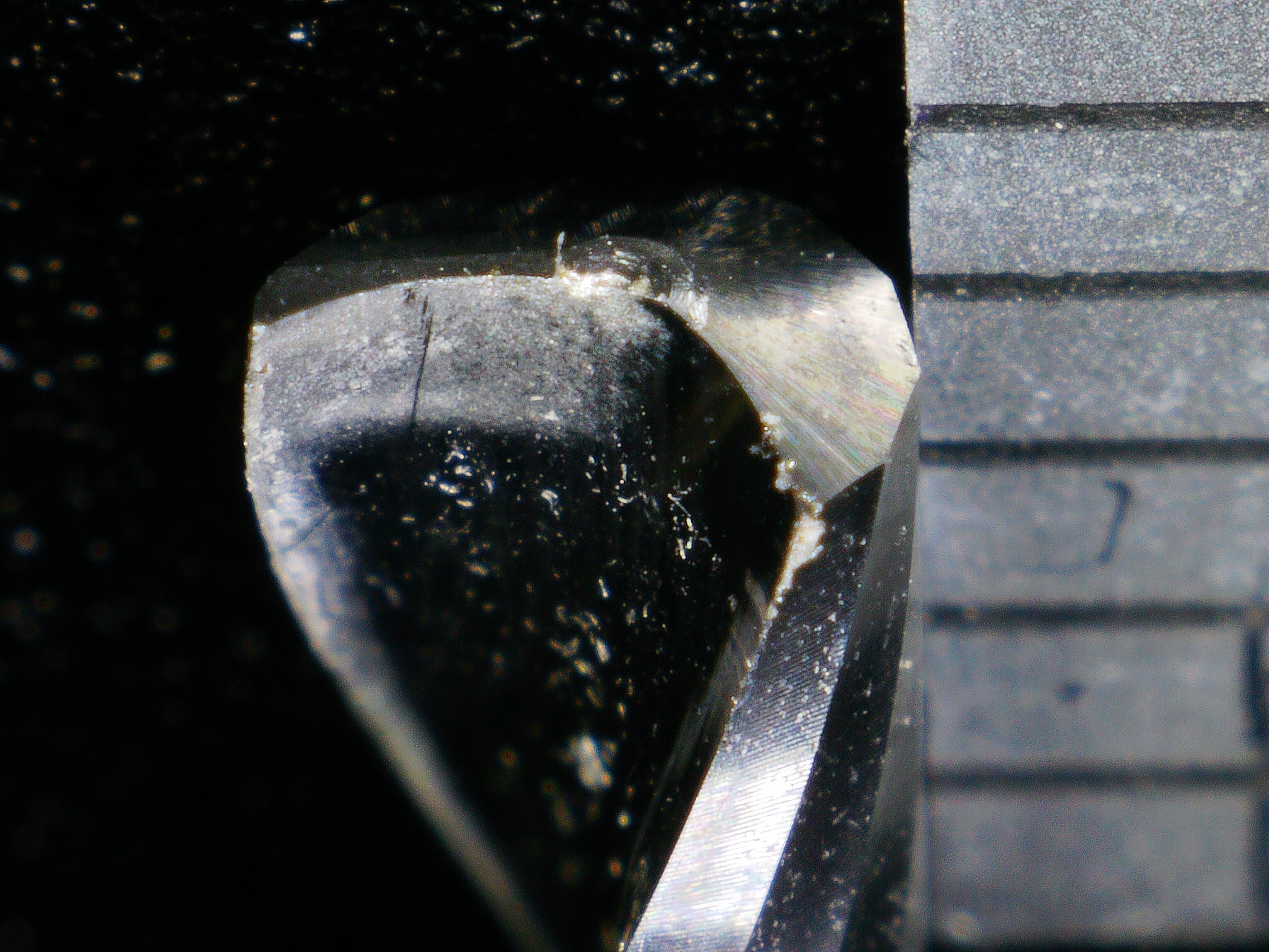
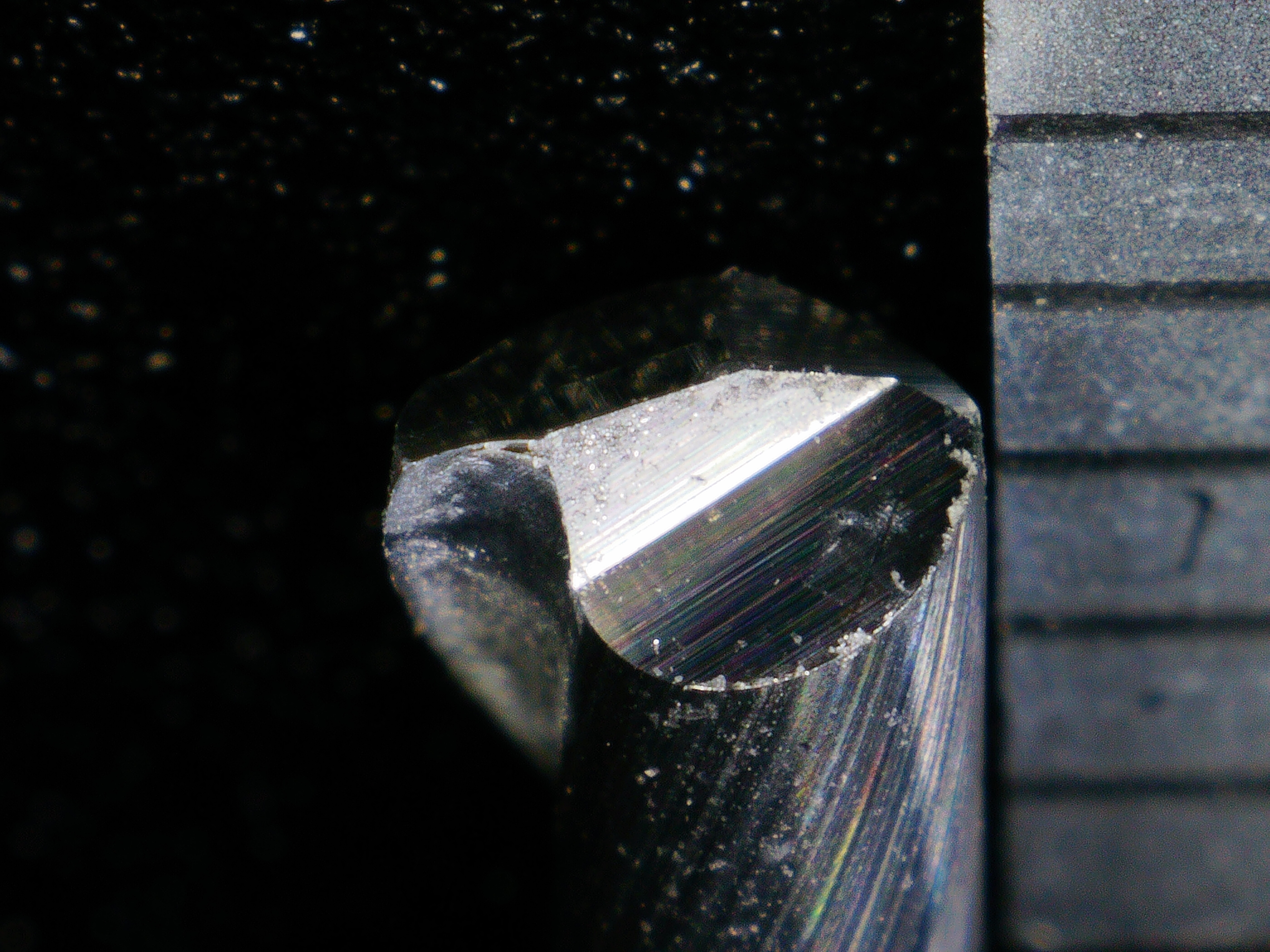
Still, I did take photos with the microscope and that’s still interesting (open these in a new tab to see full-size).
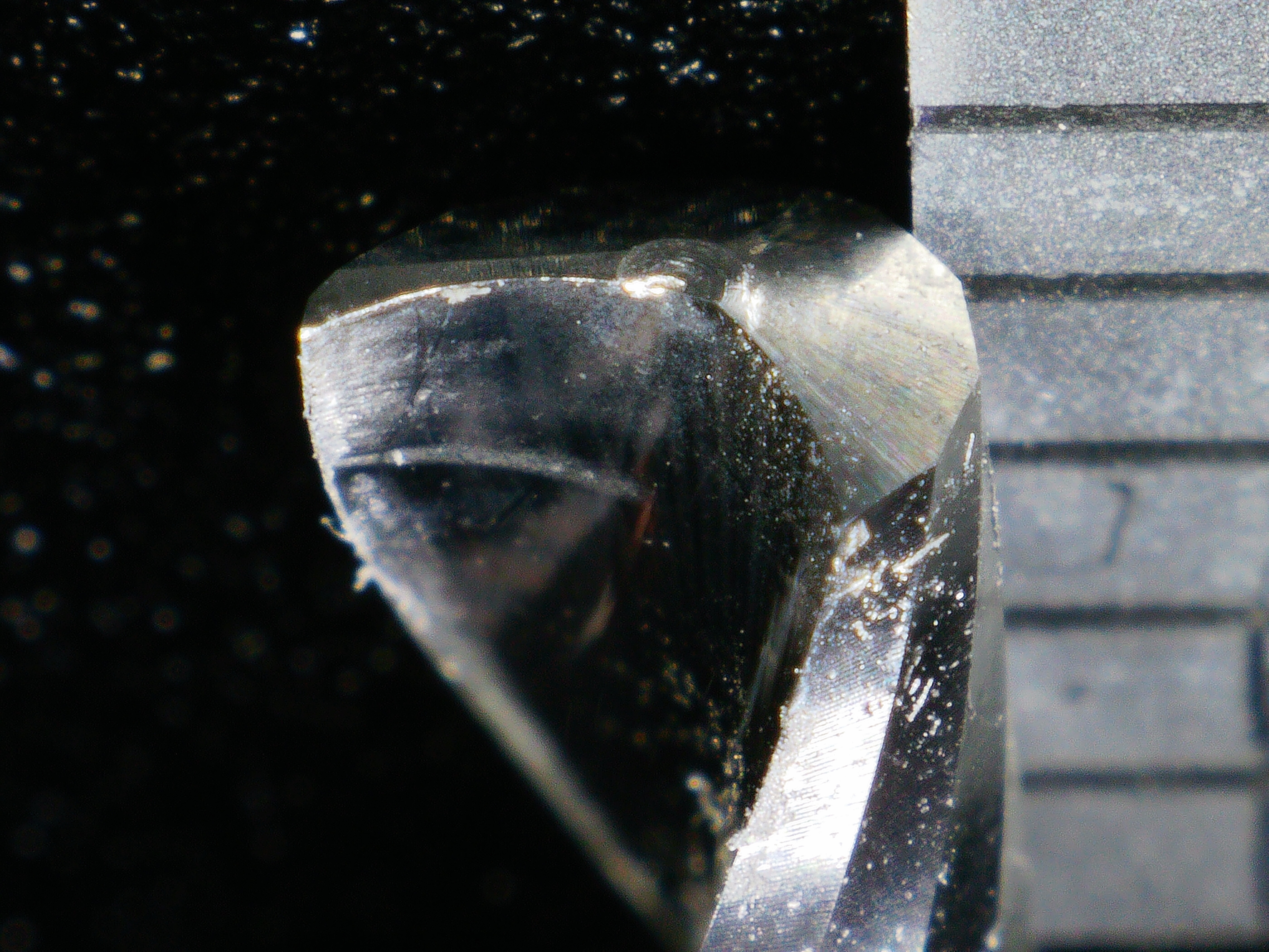
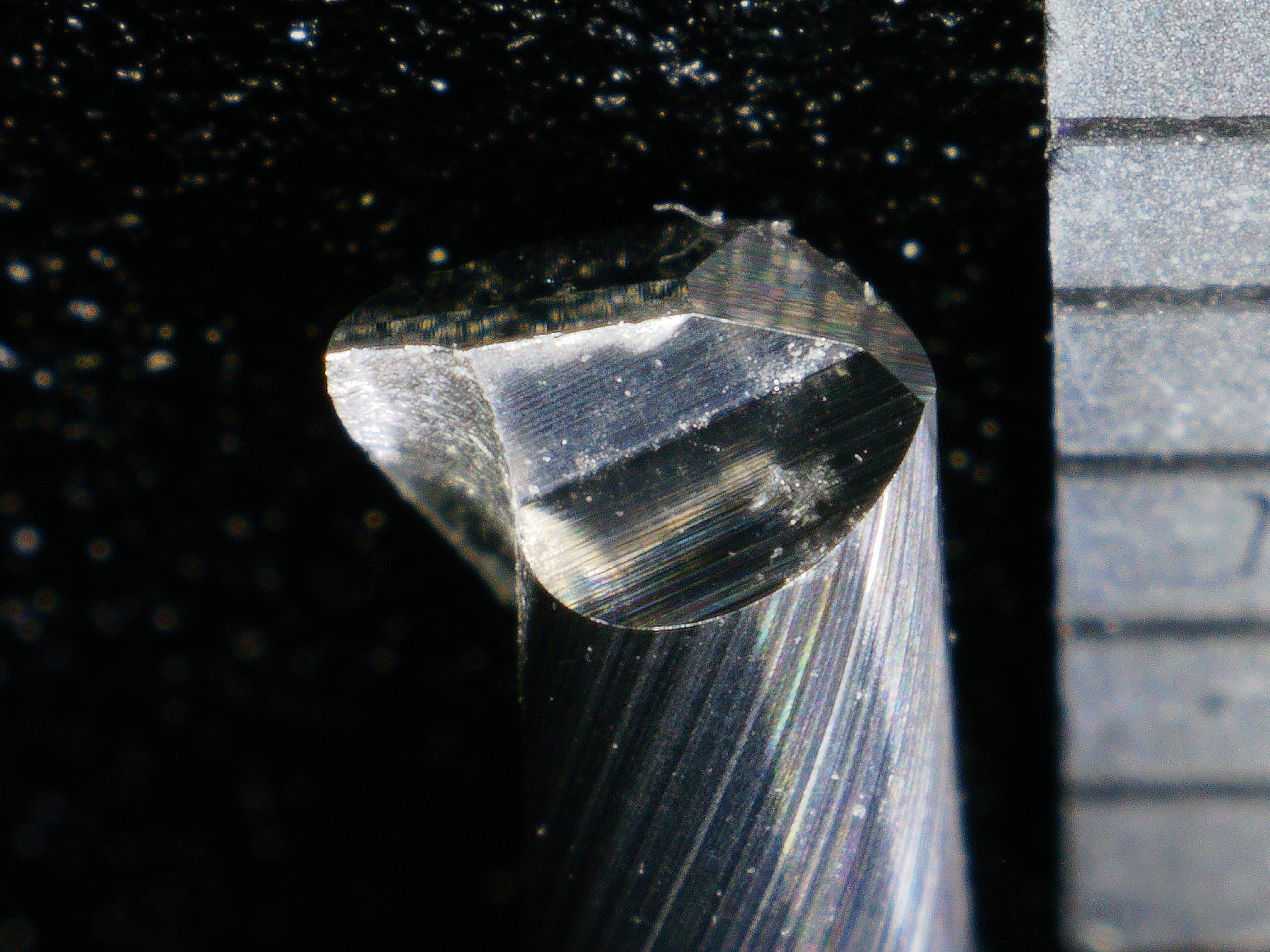
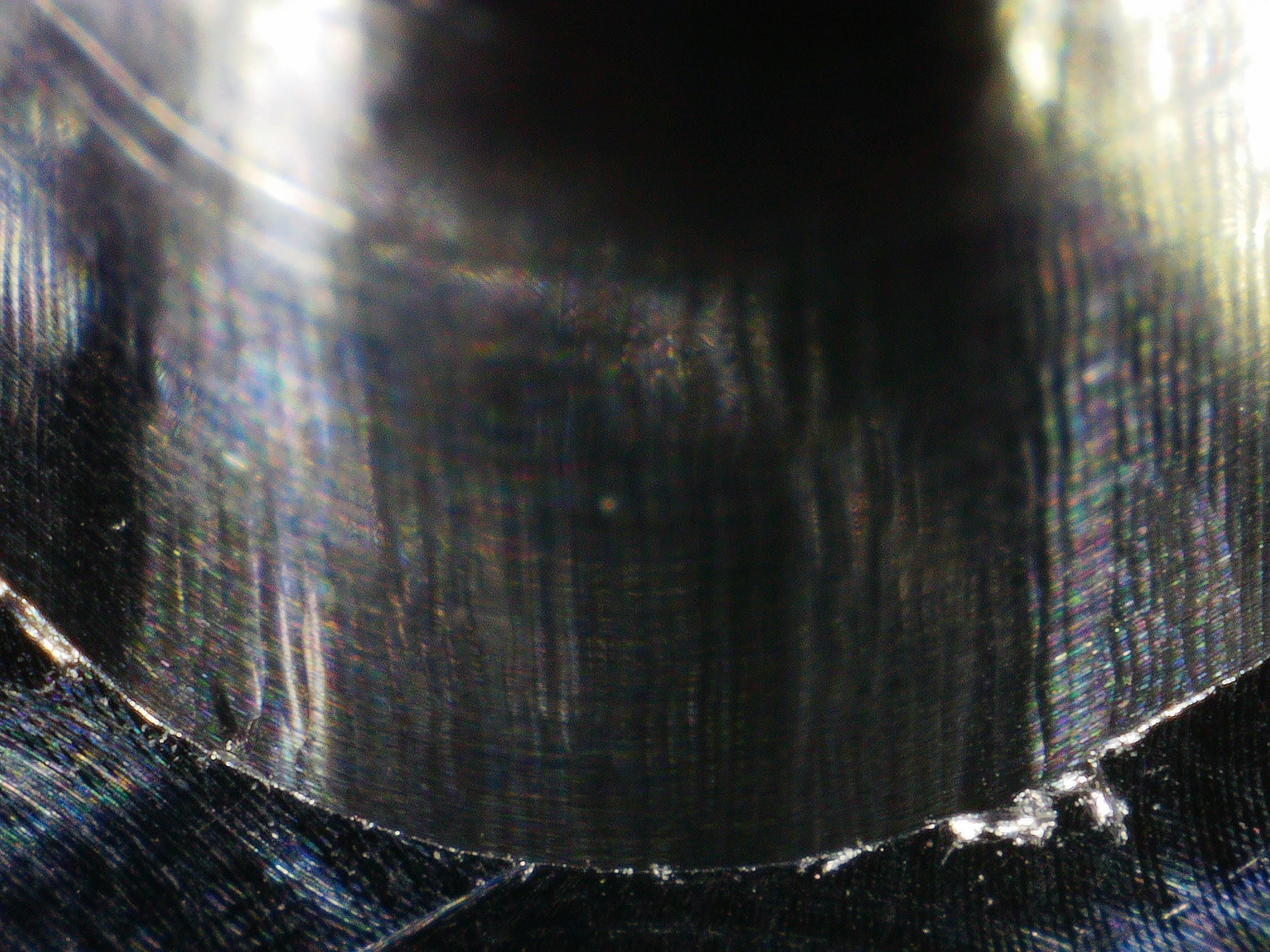
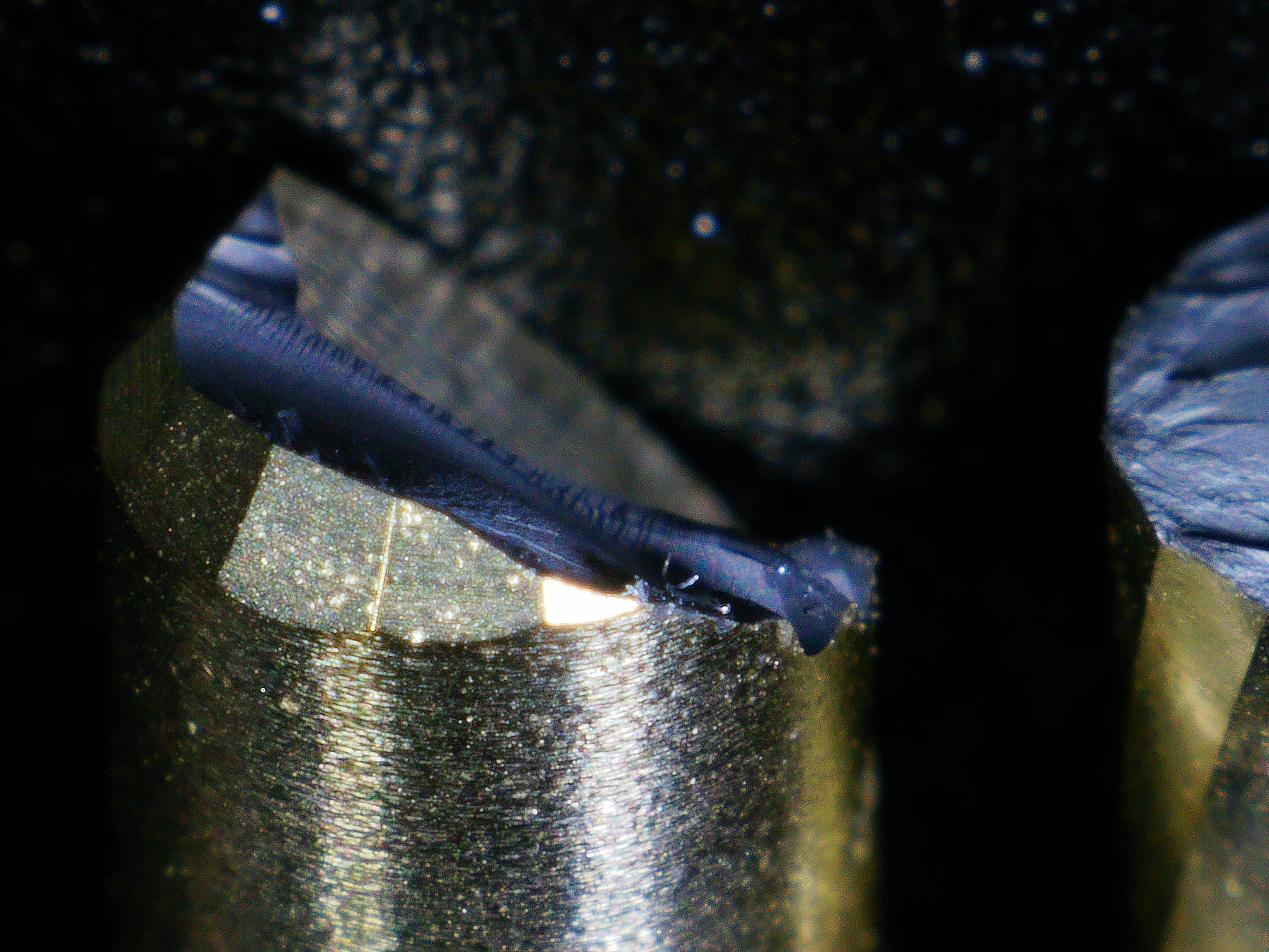
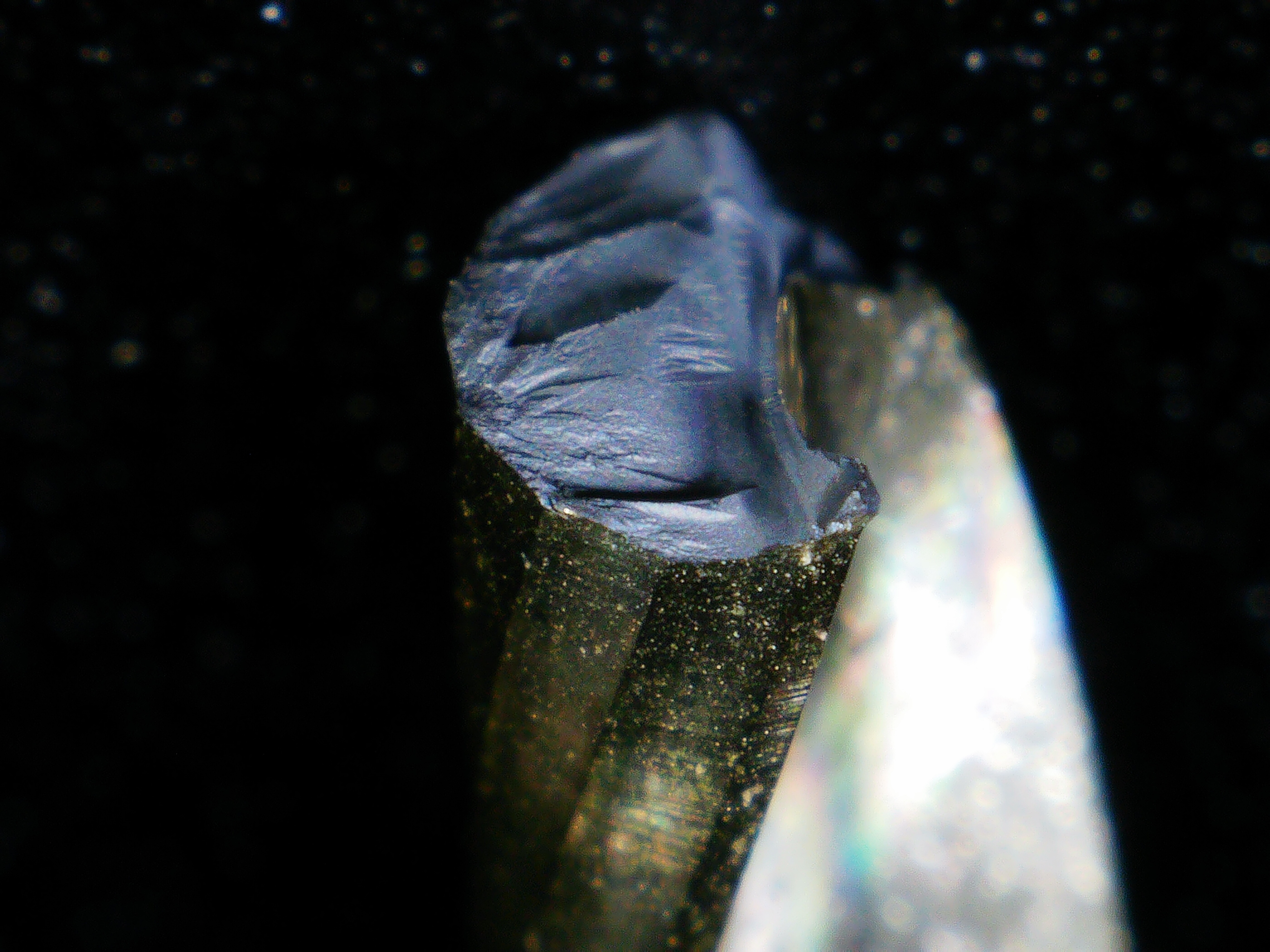
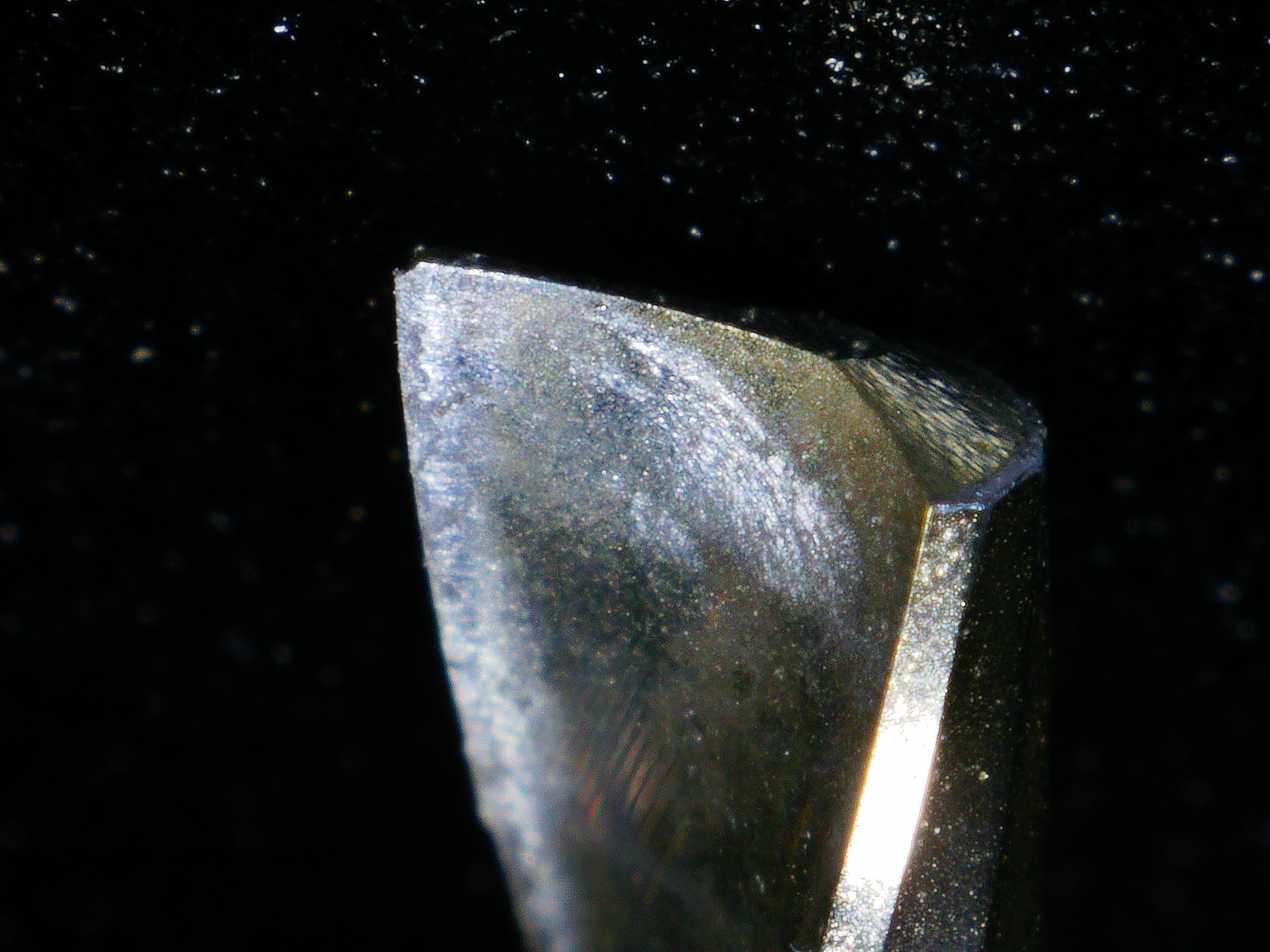
I’ll have to re-test most of these except of course the Carbide 3D endmill, which is the only one that broke. Here are some more shots of the broken endmill:
The loss of the accelerometer data might not be so tragic. It might have been hard to tell if any differences were a cause of wear or an effect of wear.