I found a place in Jacksonville with Baltic Birch in 5x5. I don’t care what the surface quality is because it will be covered with fabric. It’s only important that it be flat. I will pick it up next week on my way back home from Orlando.
Use a plane with a specially ground iron? I’ve done that in the past and I know some people sell them. I’d also look at MLCS for router bits. I’ve had good luck there.
I considered suggesting a set of hand planes — it pretty much requires a workbench suited to hand-tool planing, and that’s a rather large radius to shape by hand.
The Bridge City Tool Works HP-6FX:
has a Crown kit:
but it’s quite a small radius (2–6mm)
Usually the radius runs along the other axis.
EDIT: There are vintage (and new made) hollow/round planes for this sort of thing:
And of course, this being in plywood pretty much takes such tools out of the equation.
That said, it would be pretty easy to draw up the profile and use a series of No offset contour toolpaths to cut.
They plywood is for the inset of the frame. The actual profile will be in mahogany or sapele. I drew it and show it up above. It is doable on the CNC but I think would take way too long.
Is the design really asymmetrical, did you check more than one example, or might you have measurement errors?
For instance, the outer step on the left is 0.1815, but on the right it’s 0.165. And the numbers add up to the inner step on the left being 0.2035 while on the right it’s 0.20. And how did you measure the 4.4892 radius? With a radius gauge?
And finally, would extending the curve all the way to the ends hit the two steps on either side? In other words, could this be cut in two stages:
- Cut the radius across the entire width.
- Cut in the steps.
If so, then the larger of the two bits you found would work - except for the difference in curve radius (75mm vs 114mm). Would that be noticeable given the distance between the frames? It’s not like you’re butting up a new frame member against an older frame member.
Festool recently discontinued its LS130 sander, but they’re still available on the used market, and sometimes even pop up as NOS. One option for it was a base plate that you could cut/mold to the profile you wanted and then stick different grades of sandpaper to it. My idea is that you’d use the stock bit to get most of the way there, and use LS130 power inline sander to finish the rest.
1 Like
Thanks. Yes the frame is asymmetrical, there is certainly a chance that my measurements are off but I did validate with the customer that the inside edge is smaller than the outside.
I wish I had a scrap piece of the frame lying around but all I have to go on are the 8-10 of them already mounted to the wall. They are on a local Army base so remeasuring is a bit of a complicated process.
As much as I like a challenge and developing new techniques (and excuses to buy new tools) in this case the customer was OK with the price having the millwork shop do it and I am ok with the reduced stress level. If this were a full time job instead of a side gig I would be able to invest some more time in it but the day job gets in the way. I don’t want to spend 20+ hours on just these pieces.
I will keep my eye out for that sander though. I do have a much smaller job on my plate cutting trim for a cabinet door that I will do with the CNC.
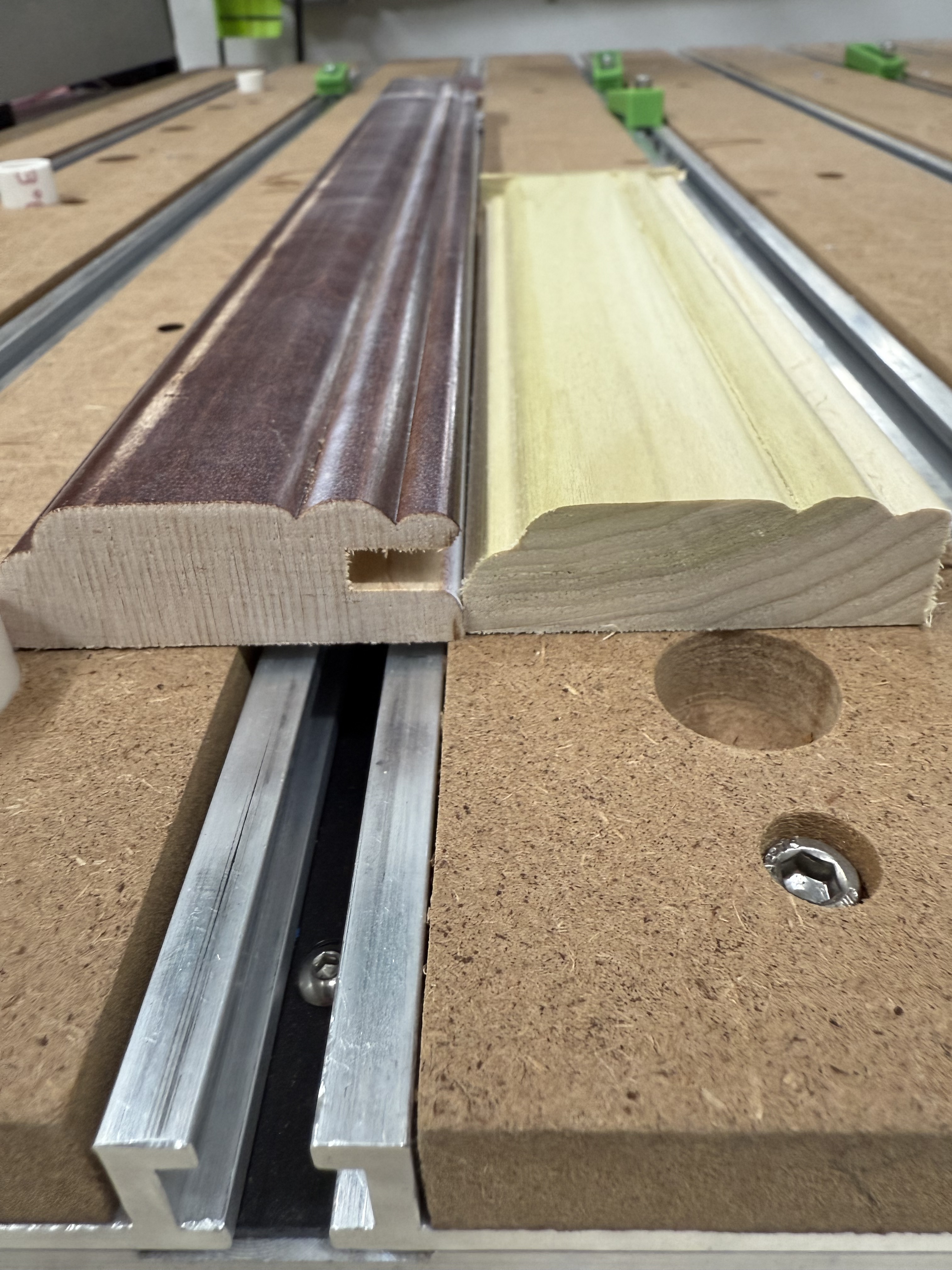
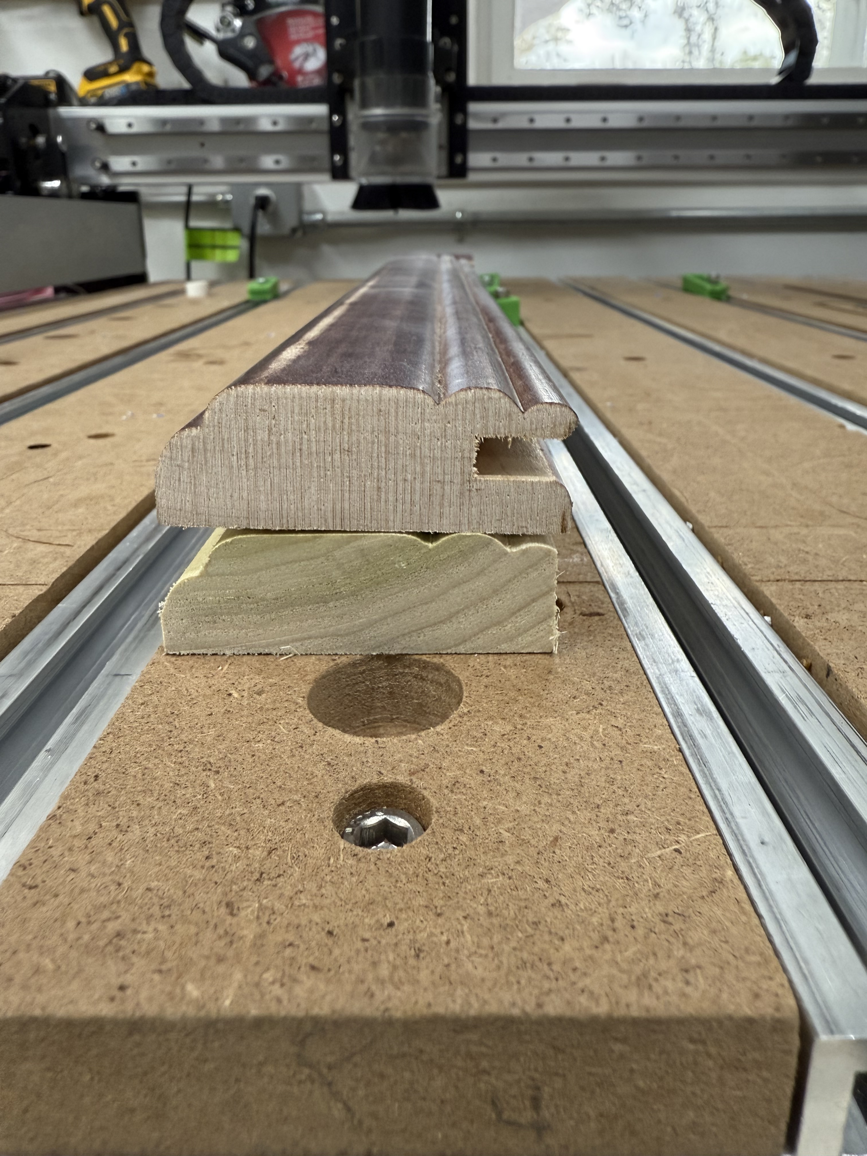
I did my test for the other smaller cabinet door test using the molding toolpath in Vectric.
This test was only 7.75” long and took about 17 minutes although I could probably have increased the feed rate a bit. It’s pretty close to the original profile. Close enough for that job. It will probably be around 3 hours of runtime just for the frames of 2 cabinet doors.
I didn’t cut the notch for the door panel in this test but will do that on the tablesaw.
I
4 Likes
I would “match existing as possible” I have matched pre-war molding and profiles many times with what is at hand… Tble saw, routers, sand paper… Most people don’t see it when it’s done the way we do. If it 1/4" different split the difference and put an 1/8" on both sides. and sand the meeting edge until it close… Once all the wood is finished no one will see it. It’s the finishing that counts. Wood is wood and not perfect. 99% of people will just be amazed that someone could do that. CNC’s have their place and aren’t the end all. I use my CNC mostly to cut patterns/templates for the router and Shaper.
It would be expensive, but I had a custom 2 bit brazed carbide router bit made for $175 a couple of years ago.
It was exactly the dimensions requested.
You could include it in the bid, and tell them that next time they need more frames, you would have the exact profile bit and could provide identical frames again.
1 Like
That is the right approach, give them a test board of the material first, and they should be able to do it. Molding knife will be much more consistent than a ton of sanding or even a router IMO. Good luck!
1 Like
I did one like this to match a crown moulding for a fireplace mantel. Mine was a full 6 inches wide and was more intricate. I used vCarve Pro Moulding tool path witha 1/4 inch ball nose. Took about an hour a foot to do that one. Came out so smooth I barely had to sand it. By the time you get this all figured out the machine could be done with the project. Based on my calculation it should take less than 60 hours. If you have a 4x4 machine you can tile if the pieces need to be longer than 4 feet using tiles. Using tile is pretty staight forward. As long as you have things tied down really well let it run overnight. So what if you dust collector runs an extra few hours. That’s why we use these machines rather than doing this by hand.
Go for it,
Douglas
First off, your numbers don’t come out correct for the O.A.W.(Over all width). you have it at 3" and when adding up the step measurements and the width of the radius, the total comes to 3.013". I know that doesn’t seem like much but it could if you were trying to hold that 3". But it is wood, so this may not matter much. I wouldn’t cut the steps in the wood until you have the radius cut completely across the side of the board, whichever way you choose to do so. Then come in and table saw the steps.
Shaping knives with the right radius would be your best bet. Yes, it will take some time, but cutting that radius on your machine would take much longer.
One other option that might work for you is if you have a sander that has the horizontal bar, or if you can make this with a lathe, you can turn the radius into a piece of hardwood and then affix a sheet of sandpaper to the inside of the radius of the rod. Then attach to a drill, and then a holder at both ends that will hold the rod horizontal, but will also allow it to turn freely enough to not bind, or burn the rod because of friction. Make sure you can adjust the rod up and down so you can start the pieces of wood into the rod and work each piece down until you have the correct radius. If this sounds too complicated, then don’t worry about it. I was thinking of this as step sanding until you are down to form.
Seems that you may never have to cut these out again, so, to me I wouldn’t want to invest in tooling that might become expensive for a job that you might only do once. The step sander idea seems more logical because if you don’t make any pieces again, you can easily throw the rod away without thinking twice about price.
1 Like
This topic was automatically closed after 30 days. New replies are no longer allowed.