Not cutting in the correct location!

I have a 4” square piece of MDF. It is mounted and taped down to the spoil board and cutting a 2” square with an outside offset. I have centered the 2” square inside the 4” material. The problem is that it is not centered within the material, offset .025” from the XY zero. It needs to comeback towards the zero.

This is particularly bad when doing a front and back and the entire piece no longer aligns. I’m at my wits end now…

I don’t know how many times that’s happened to me ( being at wits end). And I’m sure it will happen again. At least it’s just MDF. I find just turning everything off and starting over helps a lot of the time. There’s nothing more frustrating when things don’t go our way. Keep plugging away .

I centered the zero on the material and ran the square cut. It was off, so I did a measurement and found the amount and reset the zero by the difference. Now I am getting a centered square on the material! I am going to need to build a permanent fence that is perfectly placed to set zeroes with.

Put a fence on the left side. Make it out of hardwood or HDPE or something cut table and firm. Then create a job to skim the right side of that fence from front to back. This will make sure that the fence is parallel with the Y axis. This makes the actual mounting of the fence something that doesn’t require precision.

I made one of walnut and have the normal bolts holing it to the T Track. I also put some threaded inserts in the top of it so I can attach clamps there when needed which is mostly for tiling jobs. Oh, and I cut a pocket for the BitZero so that I can use it with a piece against the fence.

If I ever remake it I will put something on the bottom that allows me to remove and reposition later. Now, any time I move it I need to slice off a little more of the face to make sure it is parallel.

I would not put a permanent fence on the front unless you have a really predictable setup that you will always use. I just use a large square with one leg against the left fence and then set stops on the front. Even with that I am moving the stops all the time for one reason or another such as sliding new clamps in since it is more of a pain to slide in from the back.

Also, @KevBarn14 shows some handy tips in one of his video such as using 123 blocks to offset a piece a certain distance from the fence while still maintaining its squareness to the axis.

I am using the L bracket that came with the mounting kit and fits in the T tracks. I am building bass guitars, so I will always have a rectangle shape to start with. Two of the three jobs have a flip material in them, so Y measurement is critical and if it is not exact, the cut is doomed to start. Lost a $50 board to this issue yesterday. Plenty of hardwood to make a perfect fence with and then run samples to locate the perfect XY and build the fence around it.

Yes, that width (depending on how you flip) measurement is critical. I cut something and was off by 1/64” so given the flip it turned into 1/32”.

Others use the dowel method which I think eliminates that error. I have not tried that yet.

1 Like

So this is my thesis paper on how to get accurate 3D/2.5D/flip projects to work correctly. Spent a lot of time working this out and got a lot of support from Rob G. When the CEO is picking up your support email, I have to say I was very impressed!

So here we go…

  1. You will need some type of fence/gate on your machine going from left to right. Find a relative straight board of a height of your choice for what kind of materials you use. Drill some holes and mount it to the T Track or screw it into waste board. Get it as parallel as possible to the X axis (left to right movement).

  2. Use CC to make a little project to run a cut against the inside of that board so it is straight and parallel with you gantry. I lined my board with the front frame and it was on. Took a little bit off the inside and now I am set up.

  3. Set up your material. One straight side is all you need. Use some 123 blocks to move the material out if needed. Lock your material down.

3a. Find the exact center of your material and mark it with an X. You can do length and width measurements or draw lines from corner to corner. Just make that X. Get a nice point VBit and get it in the spindle/router. We are going to use Center XY Zero. Using the VBit makes this extremely accurate. The left lower corner and Bit Zero works great for a single side, but both side require a XY Zero that will not move. So now you can jog to the center and do a Set Zero. The advantage that we have here is all the GCode will be built relative to this very accurate center. If your material isn’t perfect, it doesn’t matter.

3b. If you have enough material, use this center to cut the material size you need with a bit square on the around your work.

  1. So now we have a Center XYZero and we have a single know straight edge on a fence. We could do the same thing without the fence, just easier to visualize like this. So get your project open and make the change to center zero and make the flip a left to right instead of top to bottom. Why? It gives us a center point that does not move. The same side of the material stays in contact with the fence, so size discrepancies won’t happen and you now have a center reference line that you can mark and match up with the spoil board or drill holes of equal distance on that center reference line for dowels to lock it in. So flip it and cut the other side.

  2. If there is a screwup or stoppage, it is pretty easy to realign everything. In fact, you can make notes of the location of the XY Zero and repeat it if you lose any material holders or your machine falls over.

All of this came out of my issues with offset when measuring the XY Zero. Perfection is achieved only when the very corner of the material is directly under the exact center of the bit. Now you can be close enough on a one side project and everything comes out fine if you do it all in one run. Second runs with a new zero can introduce problems. Where it really comes to a head is on two sided projects. Whatever amount you are off of that “perfect XY Lower Left Zero” position is how much 1 side with be shifted either up and right or down and left. One sided? Doesn’t matter.

Now on a two sided project, that offset doubles when you flip. If you did it like I did, and screwed up royally, the two sides were off by .250”(6mm). HUGE!!! It happens because it is difficult to get the XY perfect and when you do, your material better be perfect too, because if you flip top to bottom, if there is an distance change, the offset will happen and ruin it. With the center zero, it stays in the same place. A flip does not change anything. 2” from that center is the same on both sides whether you use a fence or not.

Off my soapbox for now and take it easy on me,I’ve only been doing this for two weeks.

Gonna have some fun tomorrow!!!

3 Likes

Just a follow up. It worked perfectly!

4 Likes

Looks great. But where is the fence in your thesis?

The fence is at the very front of the machine, parallel to the X gantry. Only about a half inch tall and about an inch wide. I drilled holes through it and mounted it with the T tracks. Wrote a simple CC file just to run an end mill across the side that the material touches.

No need for a left or right fence. Having this in the front and do a flip from left to right, you only have to line up the absolute center that you chose for the front side. If the material isn’t perfect length on each half, a left or right fence that is unmovable will cause an offset on that side from what was cut on the front. I have moveable clamps that I use on each corner.

1 Like

I will note that after doing a “gantry shift” on my machine, I use the lip at the back thusly (sometimes w/ the assistance of some parallels).

1 Like

The fence could be either front or back of the machine. The important part is that whatever edge you designate to go against that fence is the only one that goes against it to eliminate the movement of the material centerline distance from the fence. You could do this on the Y axis as well doing the same thing, but your “flip” would always have to be front to back. I mark and X on the exact center of both side. Once you set Center XY Zero using a sharp V bit, you don’t change the center. After the flip, you just line the center of the other side to where your bit is at when you do a positing at current XY Zero. Then lower the Z and get it right on dead center. Helps if you use a pencil with thin lead!

1 Like

You could use a fence on the left and rotate your CC file accordingly assuming you have enough depth on the Y.

It wasn’t clear from your earlier post how you make sure you are centered after the flip. You mentioned the dowel holes but it didn’t sound like you did that. Are you lining up on a pencil mark, that seems like it could be prone to error as well.

Cullen,

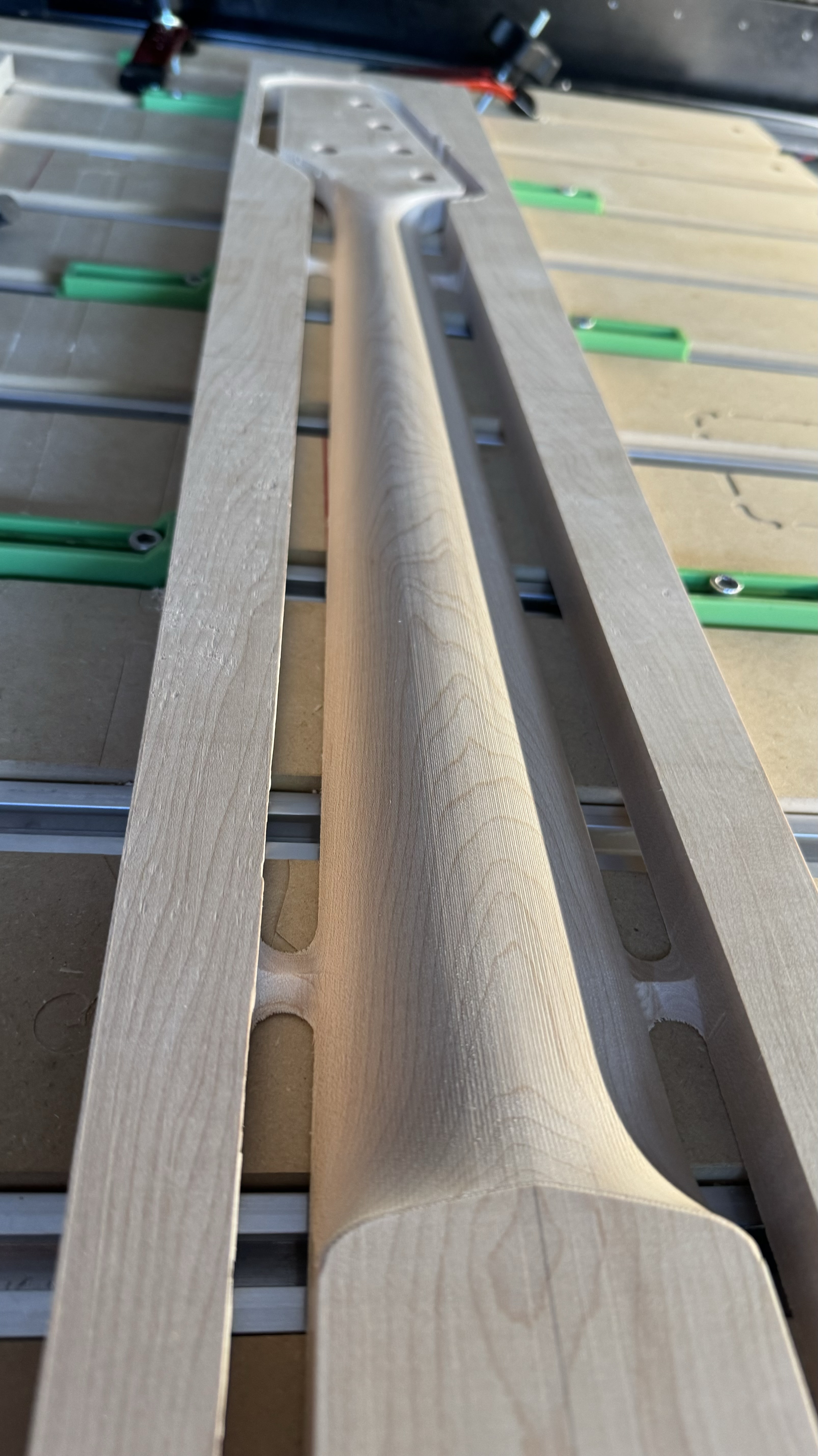
Yes, when I do the front side and set the zero to the middle of the piece, then it doesn’t matter if you have a slight difference in size on each side. To start, I mark the edge that will be against the fence and it will be the only part that touches it. If my material is perfect, I could pick any spot and as long as I repeat it on the back and there is enough material, it will work. In my case, a 38" x 6"x .8" board for a bass guitar neck. It was not exactly 38", so I just measured 19" from a side(left side) and made the vertical mark. It was exactly 6", so I made the horizontal at 3". Where they crossed, I used a sharp VBit to get exactly on it. Remember which sides you made the measurements from.

I do the whole front side, 6 toolpaths with various bits. In my case, I then flip Left to Right keeping the original side against the fence. I bring the spindle to Current XY. Now remembering which side you made the measurements from, for me 3" from the fence and 19" from now, what is the right side of the material( I measured from the left to start), I make the lines. Only bring the Z down, do not change the XY! Your fence is not moving, so you can slide the material right under the bit. Once it is there, use your clamps to lock it down. Start your job.

For using dowel pins, you would put them on the centerline of the X in my case. Your XY Zero needs to be exactly in the middle. Since I knew my material was not perfect, slight angle at the end, I did not use them. With the fence and the material same side against it, you only have to slide it left and right to get the same perfect center. I did a double check by taking the line from the front and extending it all the way around when I first set it up. With a 60 degree Vbit, it locks right on the 0.5mm pencil lead perfectly! Cut the back with 4 more tool paths and was good to go.

Full disclosure, I screwed up about 15 of these attempts until I realized that two sided cuts, or 3D cuts, will never work right from the lower left corner, or any corner. Left Center would work if you have a Y axis fence. You just always need to have the center on the midline of your model and material. I also tested BitZero, and it is accurate and repeatable, if your material is accurate. If the two corners are not equidistant from absolute center, you will have offset.

Let me know if this makes sense.

You may want to get one of these:

to avoid having to measure multiple times.