OK, so I’m making a 15 X 30 flag and have the base SO3. I am doing a Y pass through. Here’s what I’ve learned so far:
If you have flattened your waste board, you have to put a piece of 1/4" plywood over the flattened area. Flattening leaves a ridge around the flat area. When you do a pass through, the material will sit on top of the ridge and therefore cut deeper on that tile. When you move it down, the second tile will be of proper depth, leaving a ridge in your work.
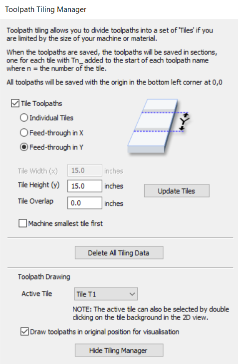
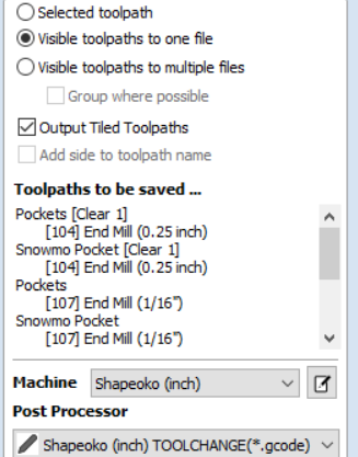
There are multiple files that come out of Desktop. One for each tile. The software always refers to the original origin. The coordinates in the files are modified to reference from the origin of each tile. So for tile 1, the origin of the tile and the origin of the material are the same. For tile 2, the Y origin of the tile is offset by the size of the tile from the Y origin of the material.
I hid a little cut at the precise Y end of the first tile. I could then use this to line up the material to set the origin for the second tile. DO NOT change where the SO3 thinks the origin is, line up the material. Maybe this isn’t critical, but I wasn’t taking any chances.
I was cutting a flag into1/4" thick oak. I found that just clamping on the edges allowed the center to flex up and down. So the size of the bit, the sharpness of the bit, etc. affect how much pressure is applied and how the material reacted. Solved this by using thicker material.
I put a fence on the Y side so I could just slide the material and not lose the X reference.
BTW, I paint before cutting. I made a gcode file that just outlines the different colored areas. Just maybe .02" deep with a V-bit. Then I paint with a brush so I can paint all colors at one time without masking. ( I hate painting )
I have VCarve desktop too and I already hit the work area size limit (24") it enforces, when generating toolpaths further than 24" from the set origin. How did you manage that ?
I see a number of folks doing this, but I always wondered if this appropriate for a tiling job, because any slight angle between the fence and the “natural” Y axis of the machine will end up resulting in a large error when sliding a long piece along the fence ? I suppose you took great care of aligning the fence with the machine’s Y axis ?
I tend to machine locating pins, they guarantee that the stock/piece will still be aligned with the machine’s Y axis after sliding. But honestly I never compared the two approaches, they may be equally efficient. Just a thought.
Do you use metal or wooden locating pins?
How deep do you embed them into the waste board?
What diameter pins do you like to use?
I ask because I did my first job with locating pins, but wasn’t so thrilled with my approach and think there is a better way
Step 1: peck drilled 4 x 1/4 inch hole through stock (3/4 inch) and into spoilboard (1/4 inch) a total of 1 inch deep
Step 2: tried to use dowels from a dowel kit I had purchased from Menards or Home Depot and realised that the 1/4 inch dowels are actually smaller than 1/4 inch
Step 3: Purchased a 3ft 1/4 inch diameter wooden dowel from Home Depot and cut them into 1.25 inch pieces.
Overall - my approach worked, but I wasn’t happy with it
I use 12mm hard wood dowels (can’t remember where I got them, must have been Amazon), and pocket holes with a 1/4" endmill, 12mm in diameter, down to ~1/4" into the wasteboard. The 1/4" endmill cutting a 12mm pocket is such that I don’t have to peck drill and the hole dimensions are almost spot on for a tight fit with the dowel.
I just like the carelessness while repositioning the piece that dowel pins allow. To be fair I use them more for two-sided jobs than for tiling jobs.
When i put a fence down for my y axes i set it then run the machine down it and cut it so it is square and straight with my y movement. Then you know it is straight.
I do the same thing but to ensure I am following the Y axis, I install my fence, then manually line up my spindle with the edge of the fence and jog it (only in Y direction) from one end to the other. This (I think) guarantees that Y (fence) is parallel to Y (machine).
I Design and build custom cabinets. and have used the tiling in v carve pro
I do the cut 8 ft long sides doing dados for fixed shelves holes for adjustable shelves rabbits for the backs. What I do is make a jig that is as long as the boards and as wide as the boards so they are snug inside of the jig attach the jig square to the spoil board .thisin sures that your start point will be right where you need it to be for the next.tile
Jeff Peters
May be a bit off topic, however, here is a good source that anyone can access (at least now) for general CNC processes and Tiling, along with a multitude of other features - but it is geared for Vectric, so read, watch, then try to do the same in CC or maybe Inkscape first and then turn into SVG files. These short videos are a treasure!
Griff
(Well crap, my hypometric precursor device is blown…)
15
Thanks for posting, always good to see others approach’s.
I like these McMaster-Carr 1/4” steel dowels from McMaster-Carr.
My practice is to bore dowel holes on 2” centers in my freshly installed spoilboards. This provides perfectly aligned references in both X and Y for the life of the spoil board.
These plastic pins come in handy if you think you might hit a locating pin.
Sorry about that link problem. I thought I had it there.
So, the first link is to the master page. The other links take you directly to that particular process. I would recommend that you Browse the full extent of these tutorials to see what is available. The links follow!