I have been learning on ccv7 and this morning i was creating sectional pieces for a simple drawer organizer for silverware. The grid, sized to my stock, was getting pretty cluttered, so after i used the grid to make the basic design, i grouped parts together and designed off the grid. Theres a few ways in which designing off the grid was helpful, but also designing on the grid is helpful as well.
This has got my wheels turning. Are there other reasons, during design to do this. I suppose, im more asking in hopes of picking up some useful tips and tricks. Tutorials are great but sometimes i find the overlap in the ‘basics’ tough and just want someone to blurt out the answers ![]()
Thanks for your time!
1 Like
I constantly change the grid size while working, and will frequently move things temporarily so that a node will align w/ a grid intersection so as to allow for a specific edit.
1 Like
I find myself changing from inches to mm a fair bit as well. Grid in inches, then fine tune in mm.
Am i right to assume the machine only cuts what is on the grid? Example, if i make a cicle and it is half on the grid and half off the grid, what will the machine do?
Circulate and cut only the half circle or will it rotate and cut the entire circle?
This assumption is based on a tool path already created for an entire circle
No, the grid has nothing to do with design save for things lining up during creation/editing.
The underlying grid is that of the steps/mm for the stepper motor microsteps and the movement of the mechanics.
For the Gates GT2 profile 2mm pitch belts, w/o calibration at 1/8 micro-stepping this is 1/40th of a mm — but the firmware will interpolate for movement in-between that grid where the motion calls for it.
1 Like
I will second that.
My spindle went in an unexpected direction one day. I looked at the file again and realized I had some off grid/off material geometry that had a toolpath assigned. It was a copy, paste, drag off the grid for later kind of thing but I already had the path assigned and it stuck with it and tried to cut.
1 Like
Oh snap, thats not a good thing.
Ive only made one project other then a simple lettering piece. The second one, i had multiple things going on and basically it was piece work to overlay things. So i cut one thing at a time but had multiple other cuts and tools paths off grid. I did put all off grid toolpaths as ‘disabled’. It did work out, thankfully. Are you saying that there is still a possibility that even on disabled, the machine could wonder?
No. Disabling is good. In my case I had the off grid and on grid geometry using the same toolpath definition. My off grid piece was way off so I just didn’t notice it when in the toolpath tab.
I routinely have multiple step jobs where I keep all the geometry in a single file but then enable and disable various paths and save the file under new names indicating the steps. That helps me keep things aligned properly.
1 Like
I feel like ive stated to do that myself.
Organization is always key for me
I have several jobs with customizable features. Imagine a coaster with a design & a name or date.
I can edit text for the name/date, but to switch out the design I will either sort them by layer, or just move the designs I’m not using off to the side.
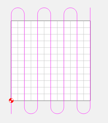
I also create toolpaths that are intended to cut off the part/workpiece. Best example is a surfacing path where the stepovers are off the part.
The stock in CC is for simulation, 3D modeling, and also for the preview in CM.
It gets output to CM as comments in the G-Code.
(Design File: )
(stockMin:0.000in, 0.000in, -1.750in)
(stockMax:2.500in, 14.000in, 0.000in)
(STOCK/BLOCK,2.500, 14.000, 1.750,0.000, 0.000, 1.750)
2 Likes
This topic was automatically closed after 30 days. New replies are no longer allowed.