Application 1: What to do with all that scrap wood you have lying around.
With all the CNC and woodworking projects inevitably you end up with a lot of wood scraps. So I made a bunch of box and lids. Here is how you can easily design a bunch of custom boxes. For simplicity I’ll cut both the box and lid on the same stock, you may want cut then separately depending to optimize the size of your scraps.
I will be using a 1/4" endmill. I will make my wall thickness 1/4" as well. If you use a different size, you may have to adapt the technique.
Design:
Step 1
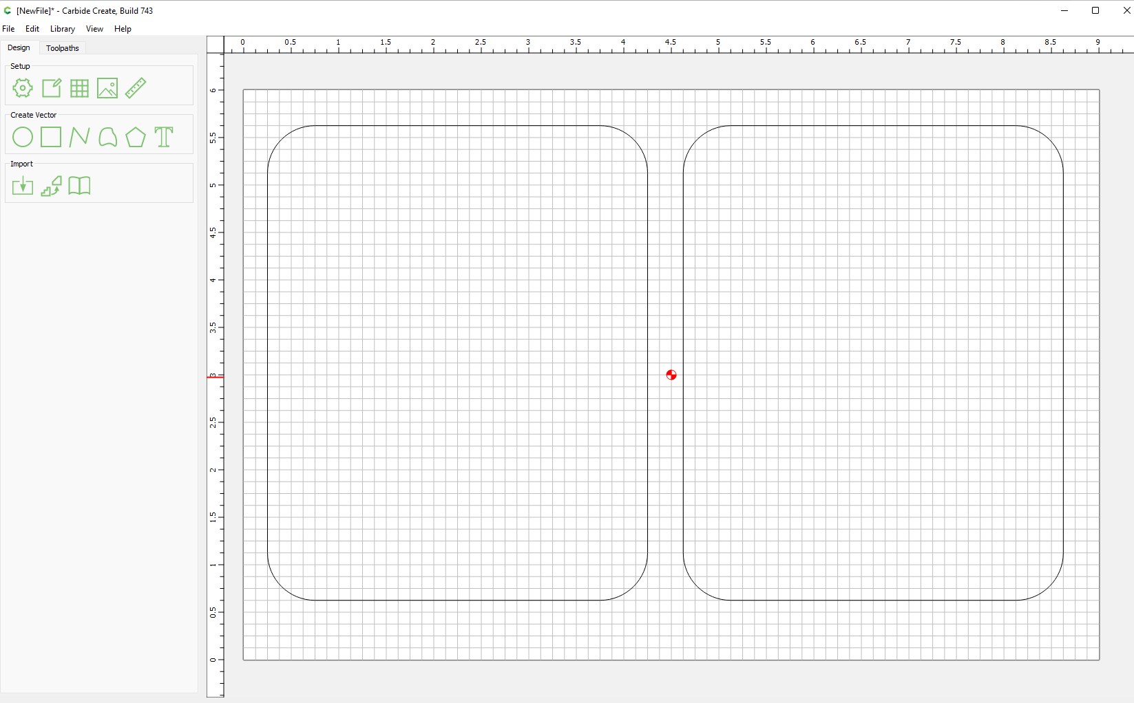
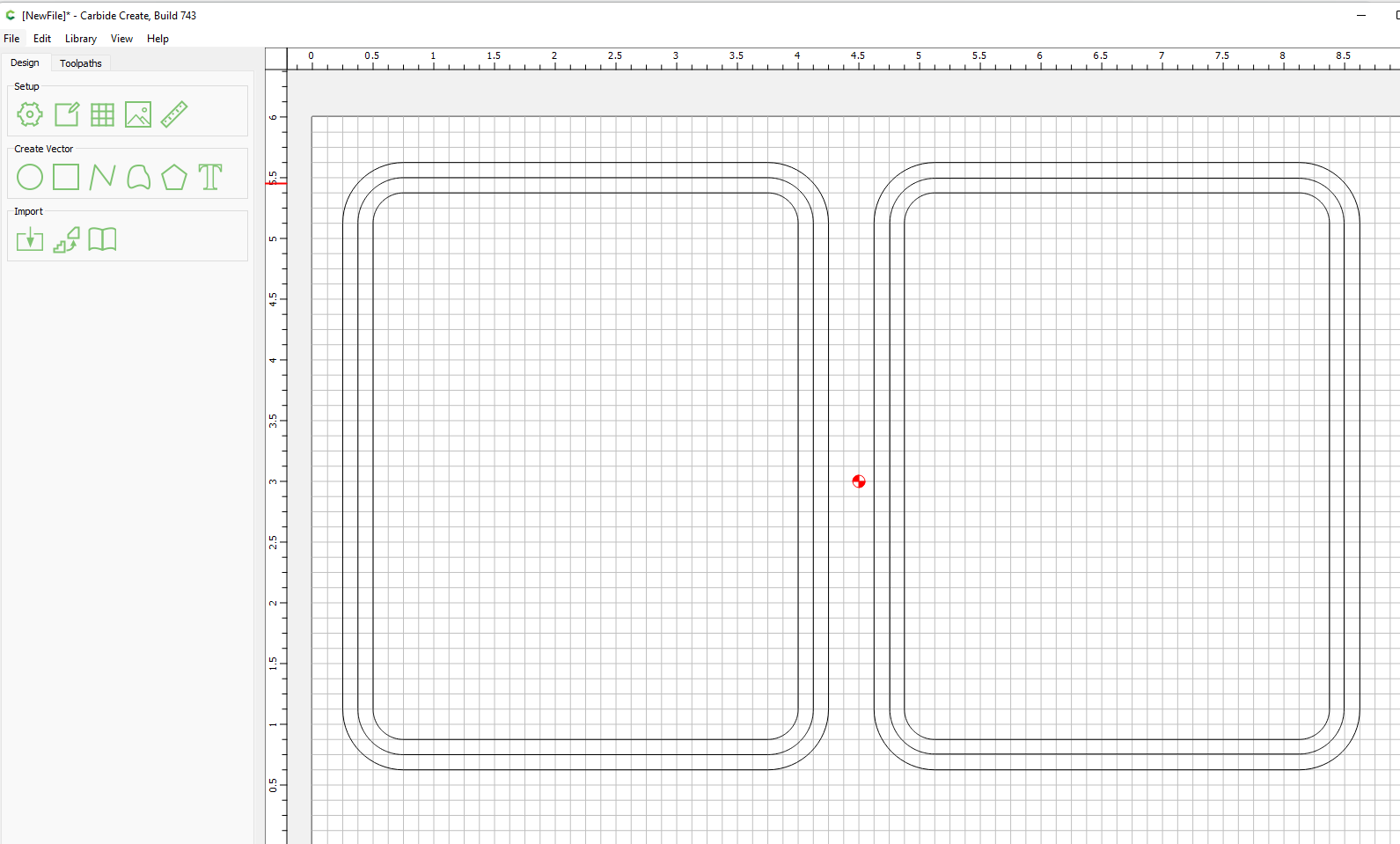
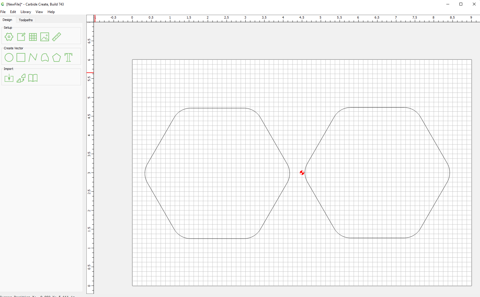
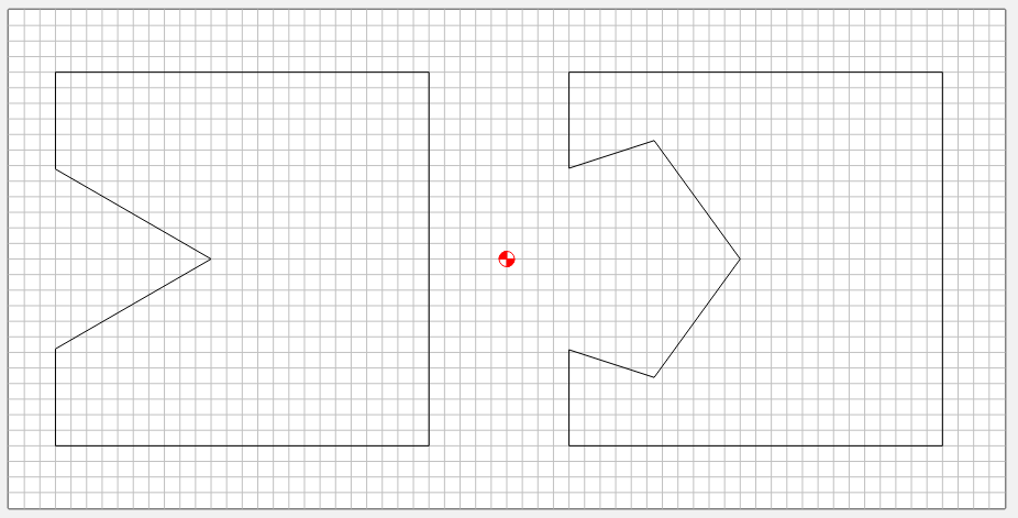
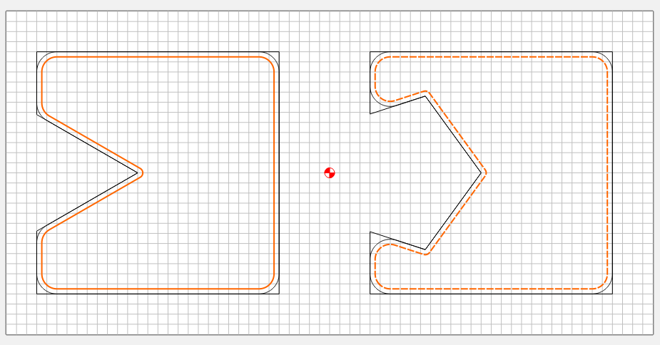
Start out with a rounded rectangle of your choosing. In my example the left will be the lid, the right will be the box. Use the fillet setting on the rectangle and choose a radius equal to your bit diameter plus your wall thickness, in my case 0.5".
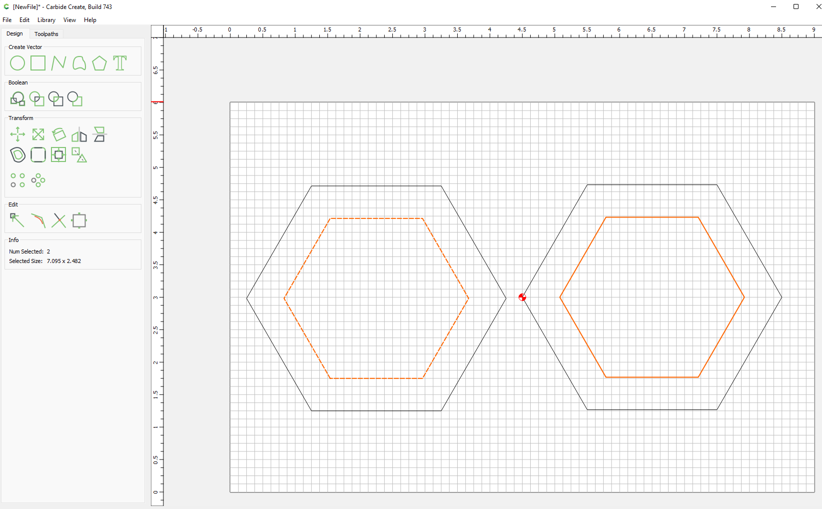
Step 2
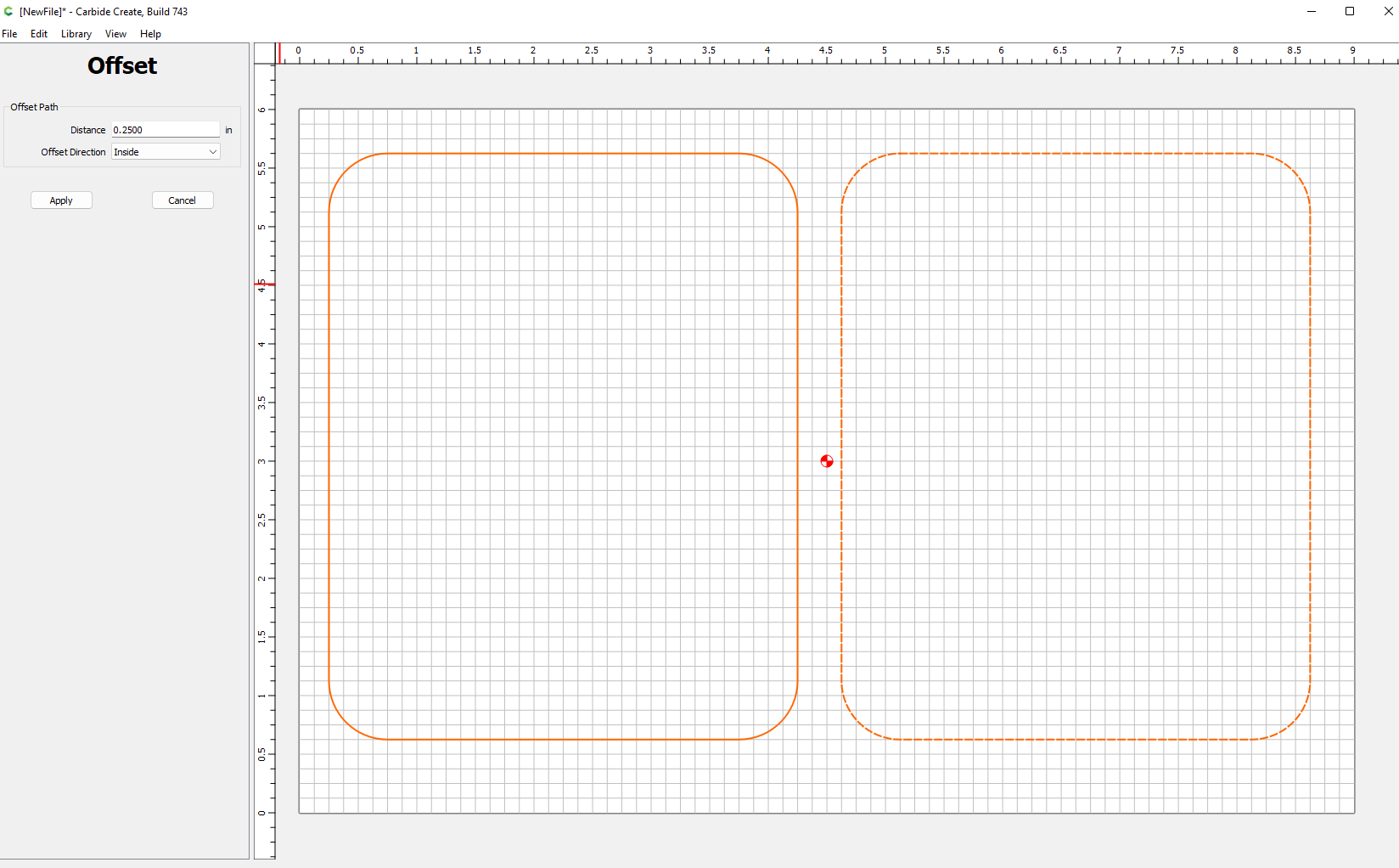
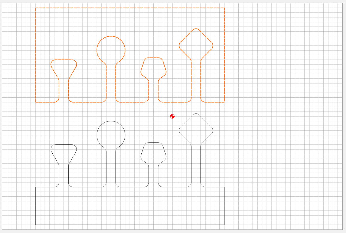
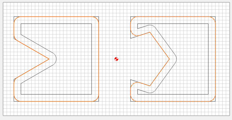
Select both rectangles and use the offset vector feature to offset inside them by the wall thickness.
resulting in
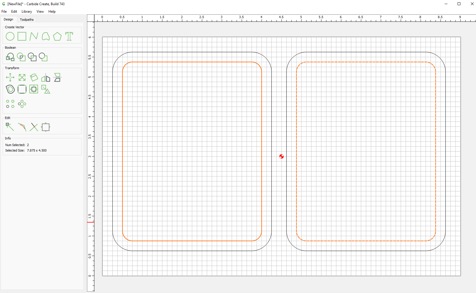
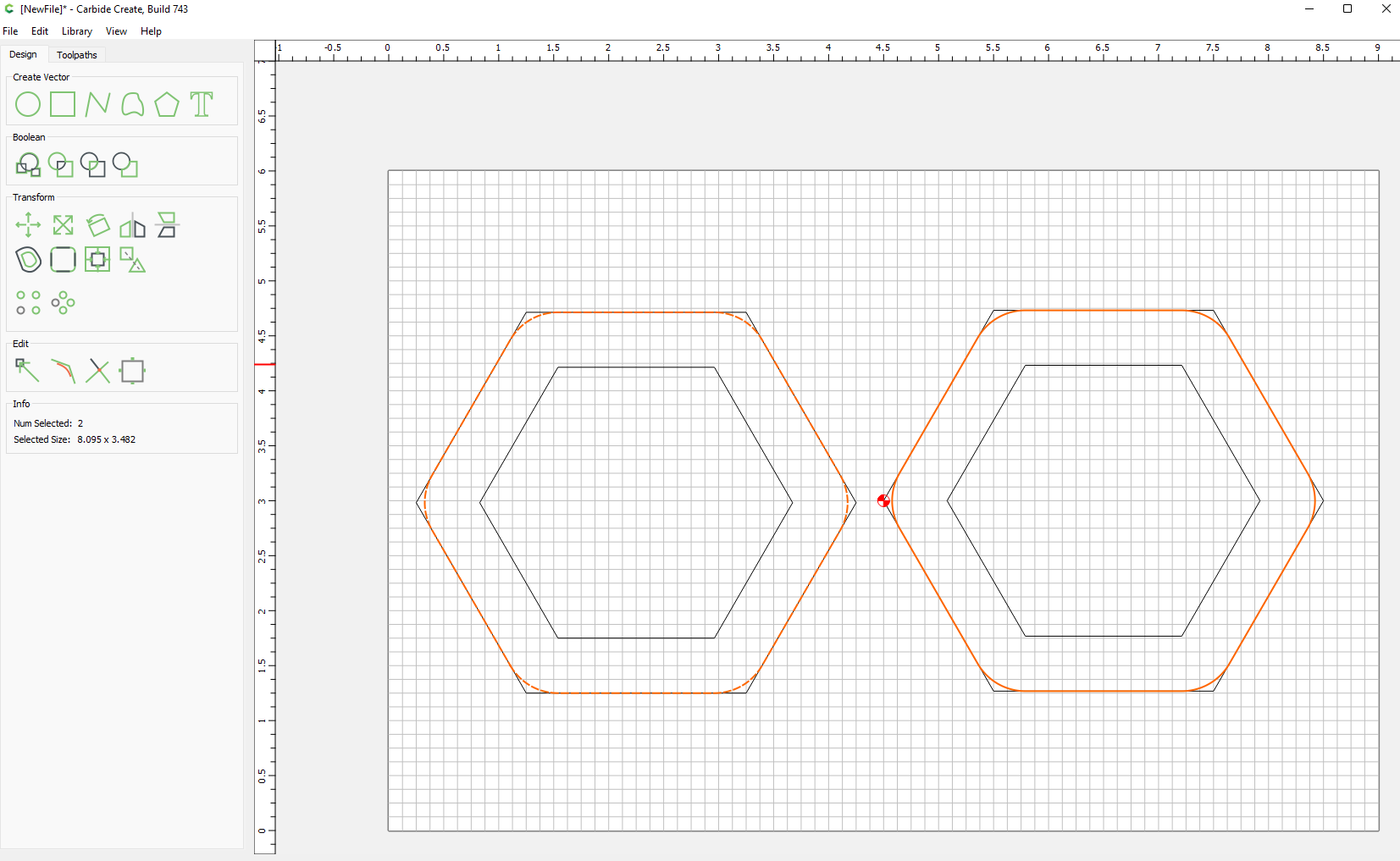
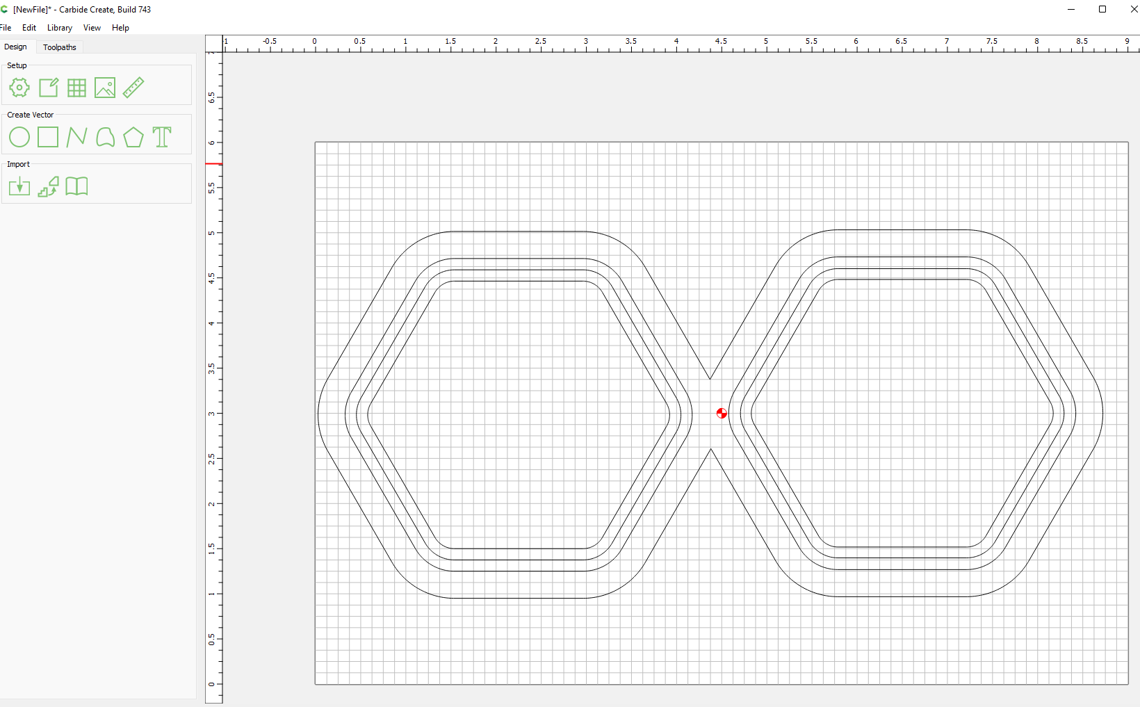
Step 3 create offset for lid lip.
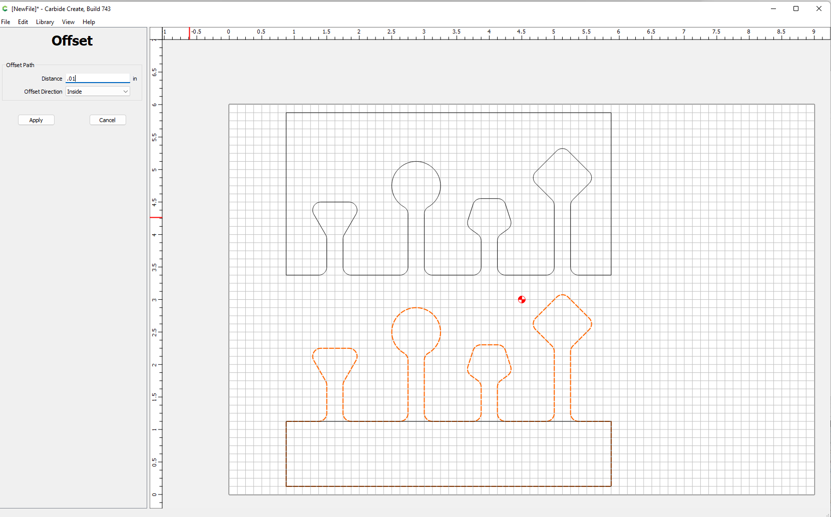
Select the lid path and offset it by half the wall thickness
Step 4 create offset for box lip.
Select the box path and offset it by half the wall thickness plus a small margin. If you don’t add this bit of slop your box and lid may fit so tight you’ll have a hard time pulling them apart, but since this is scrap wood. Try it and see  . I went with 5/100". So instead of .125", I offset with .13"
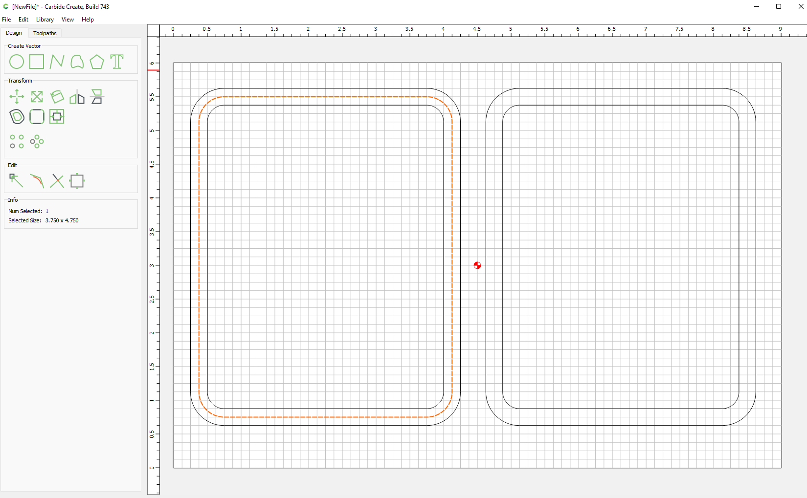
Step 5 (Optional) create a pocket for removal
You can simply contour the outside if you prefer, but since I’ve been preaching pocketing over contouring for thick stock, I’ll demonstrate.
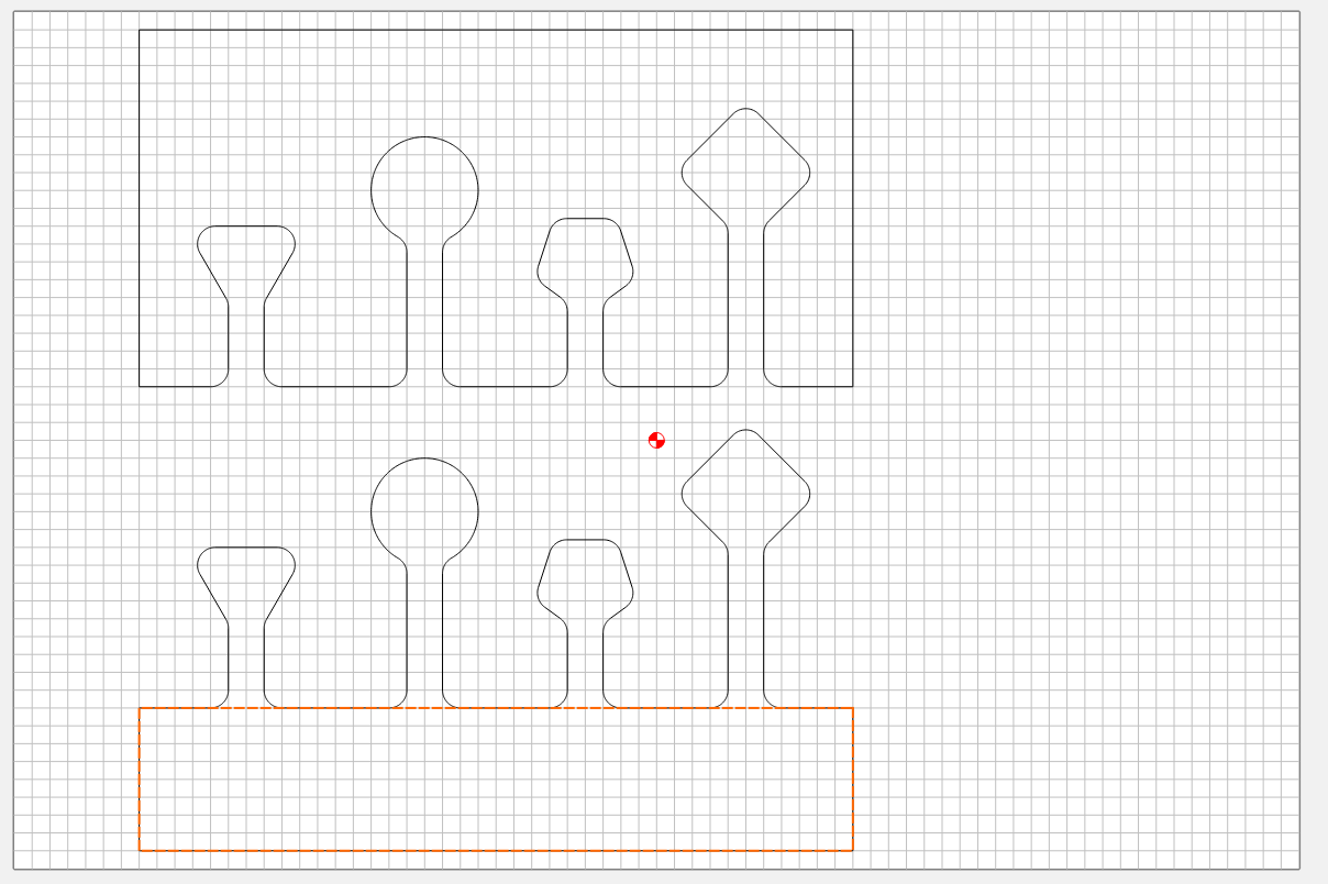
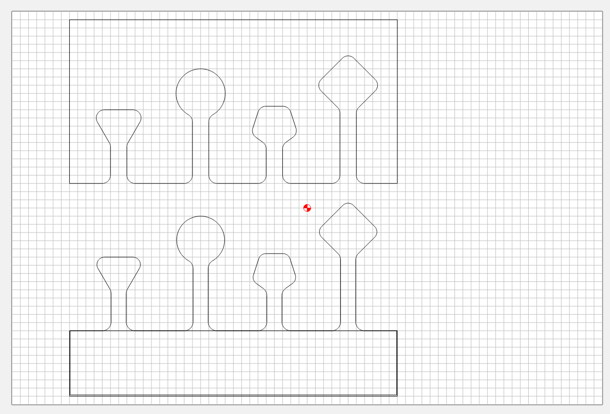
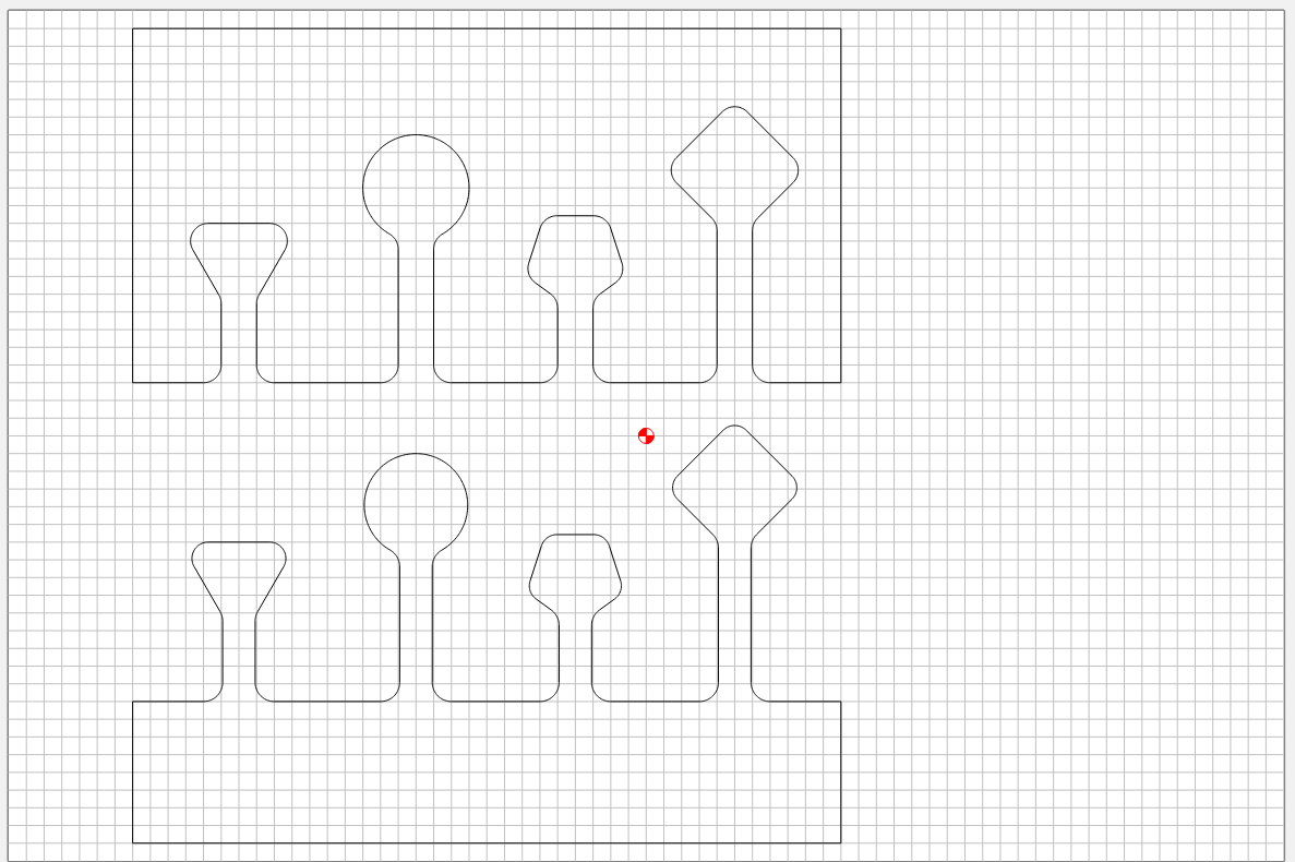
Offset the original vectors by a little over the bit diameter (I used 0.3")
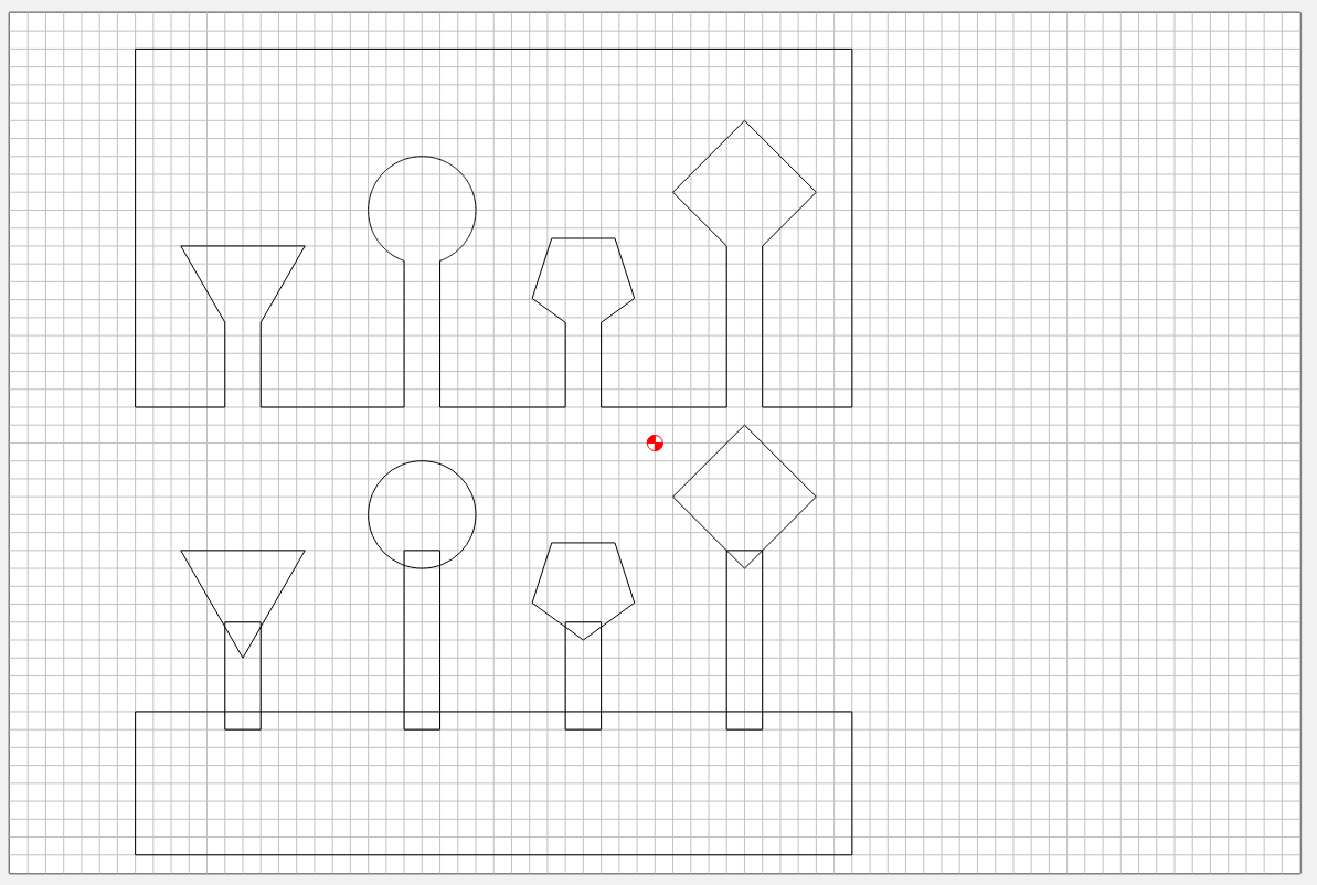
Toolpaths
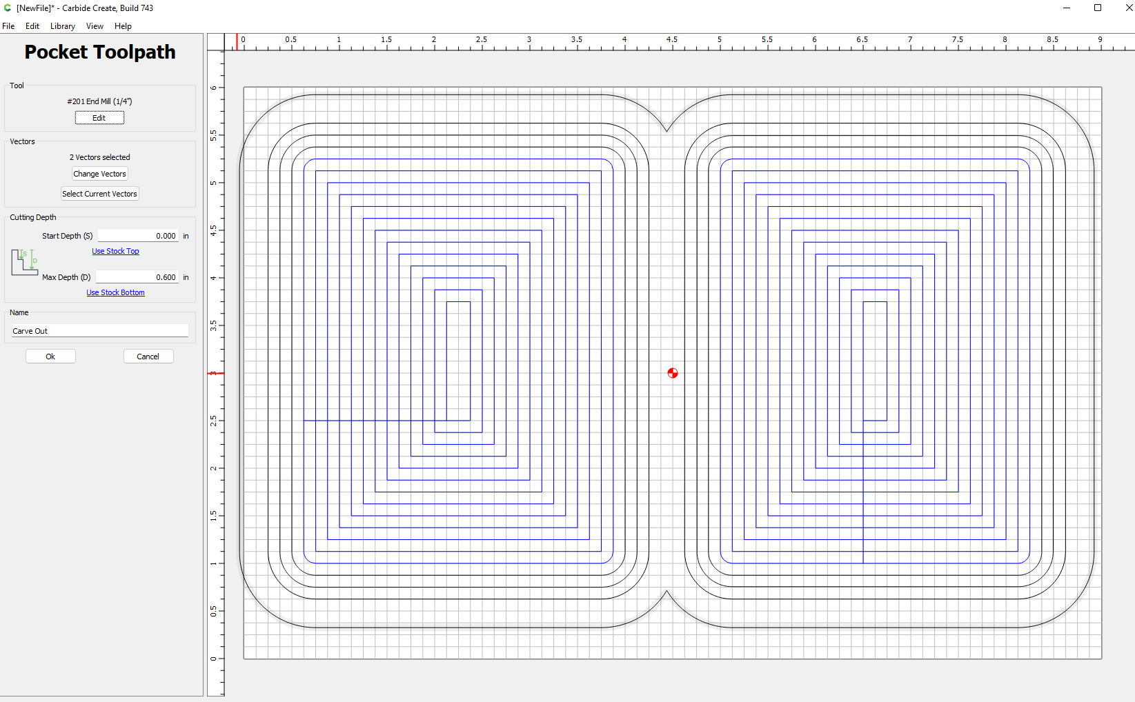
Path 1:
Carve out the inside of your lid and box. Pocket the innermost vectors. I’ll demonstrate with an endmill, but in practice I use a bowl bit so I get rounded edges on the bottom.
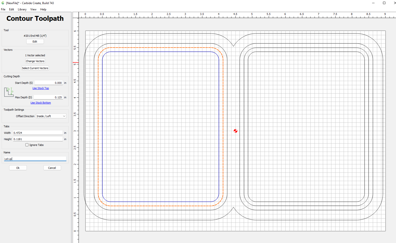
Path 2:
Contour the shape of the lid lip, by selecting the middle path and contouring on the inside. I used a depth of 1/8". (I also disabled the each toolpath after I created it so you can see what I just added.)
Path 3:
Contour the shape of the box lip, by selecting the middle path and contouring the outside. Depth should be at most the the depth of the lid lip, but can be smaller if you want.
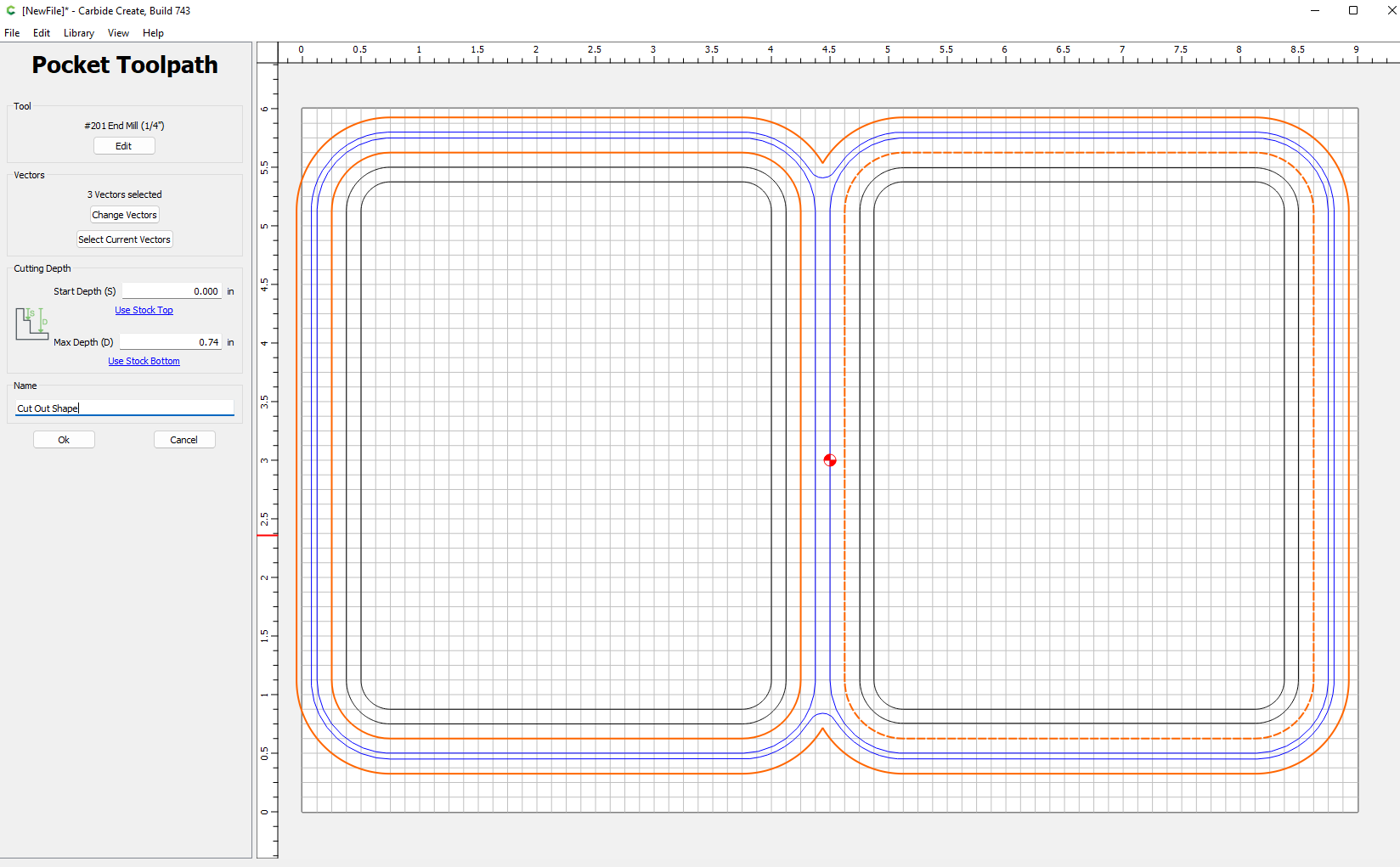
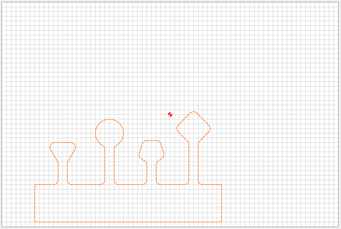
Path 4:
Cut out your box and lid. In the pocket cutout technique select the outer paths of the box and lid and that last offset path and create a pocket path. If you use a tape and glue workhold you can cut all the way through. I prefer not to and use a trim router to clean the last bit, but that’s my preference.
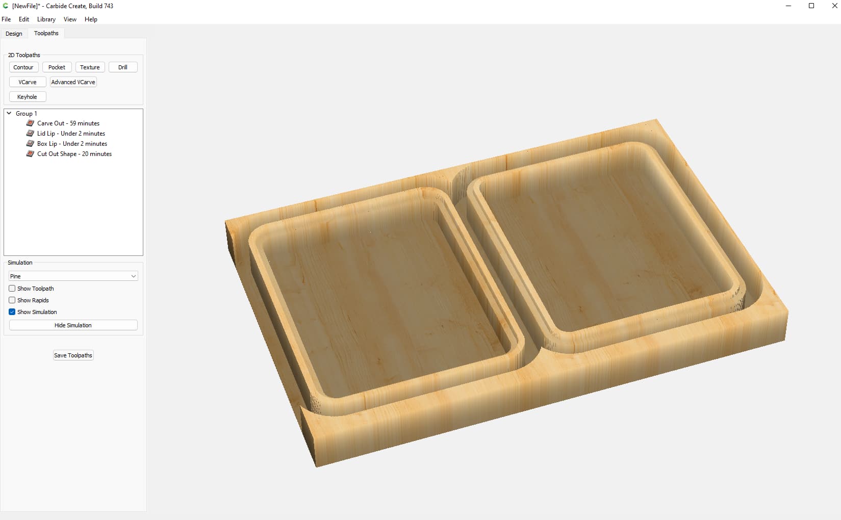
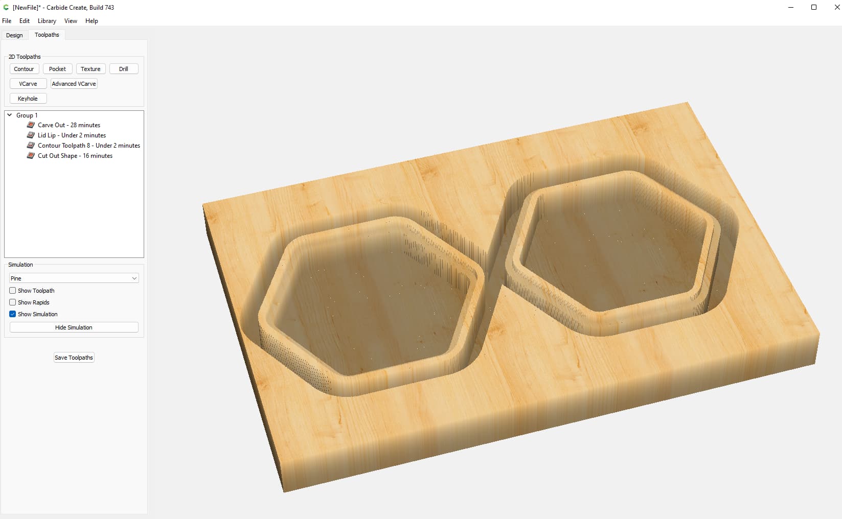
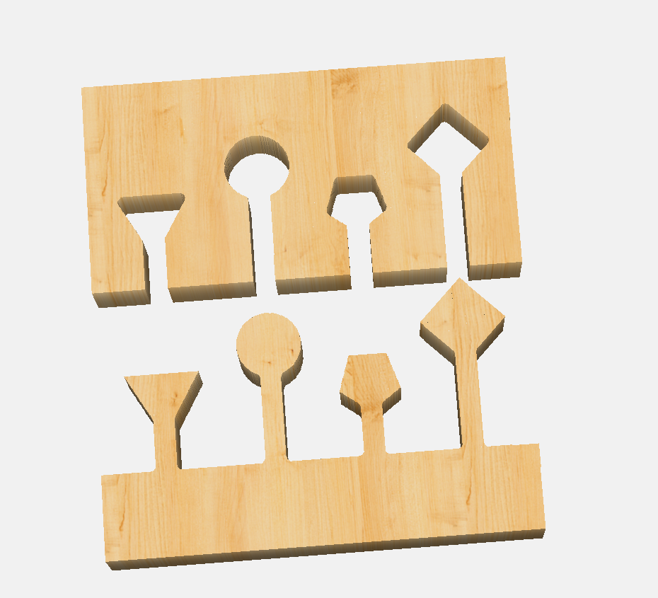
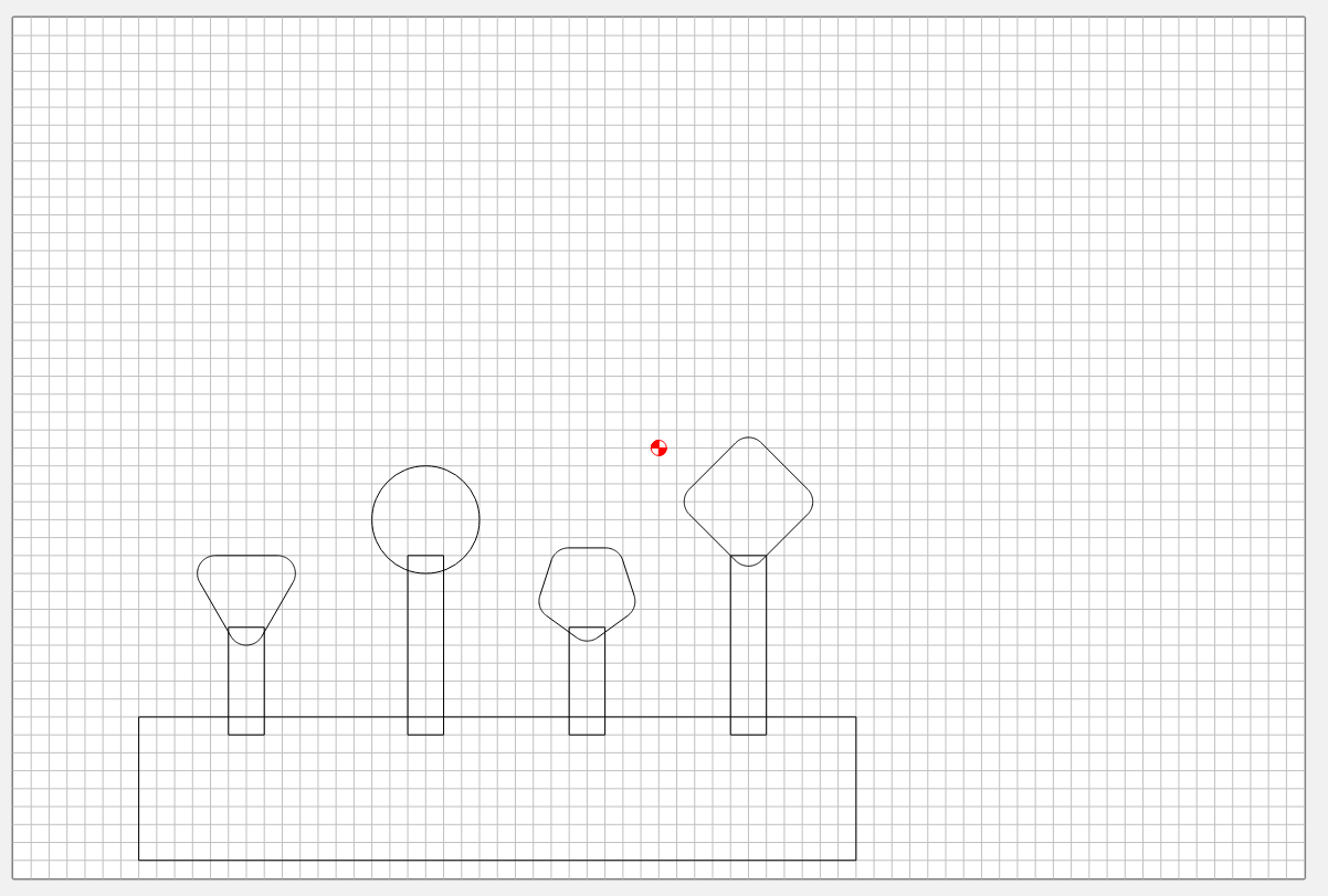
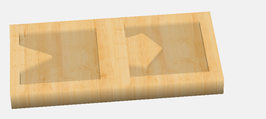
Simulation
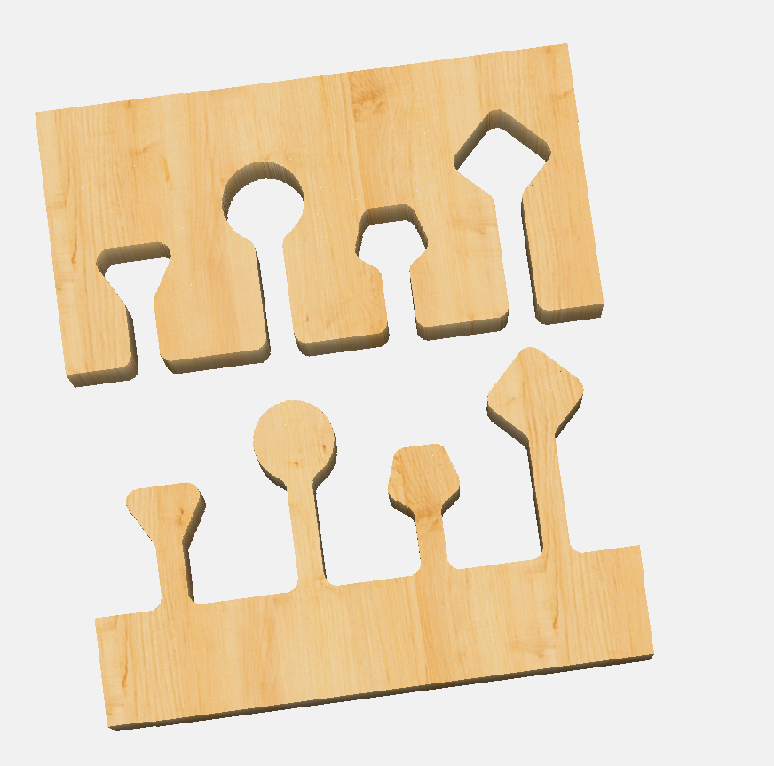
Here’s what the simulation looks like:
Finishing Touches
I prefer to use a roundover bit on trim router to round the lid top and box bottom.
Here is the demo file I just created:
scrapwood_box.c2d (108 KB)
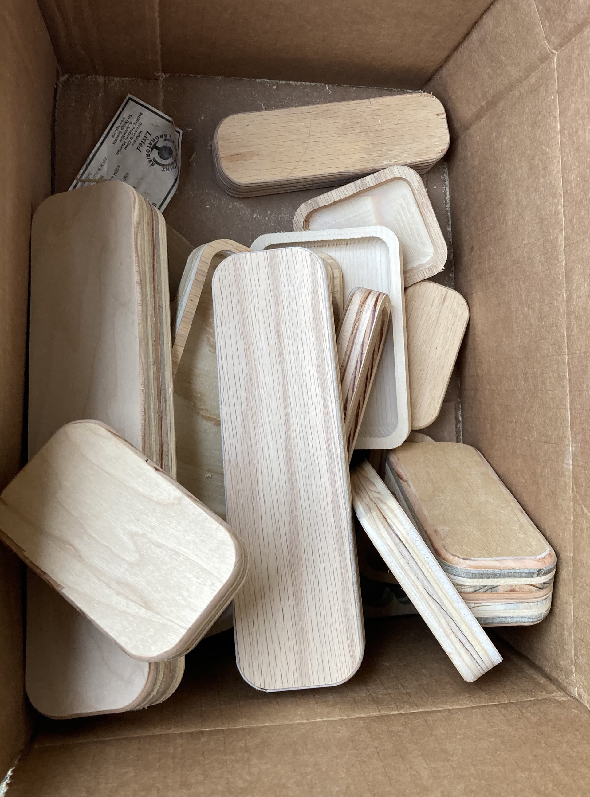
A photo of a finished box
Now instead a pile of scrap wood I don’t know what to do with, I have a pile of wood boxes I don’t know what to do with