Having some issues with my projects being offset up and to the right.
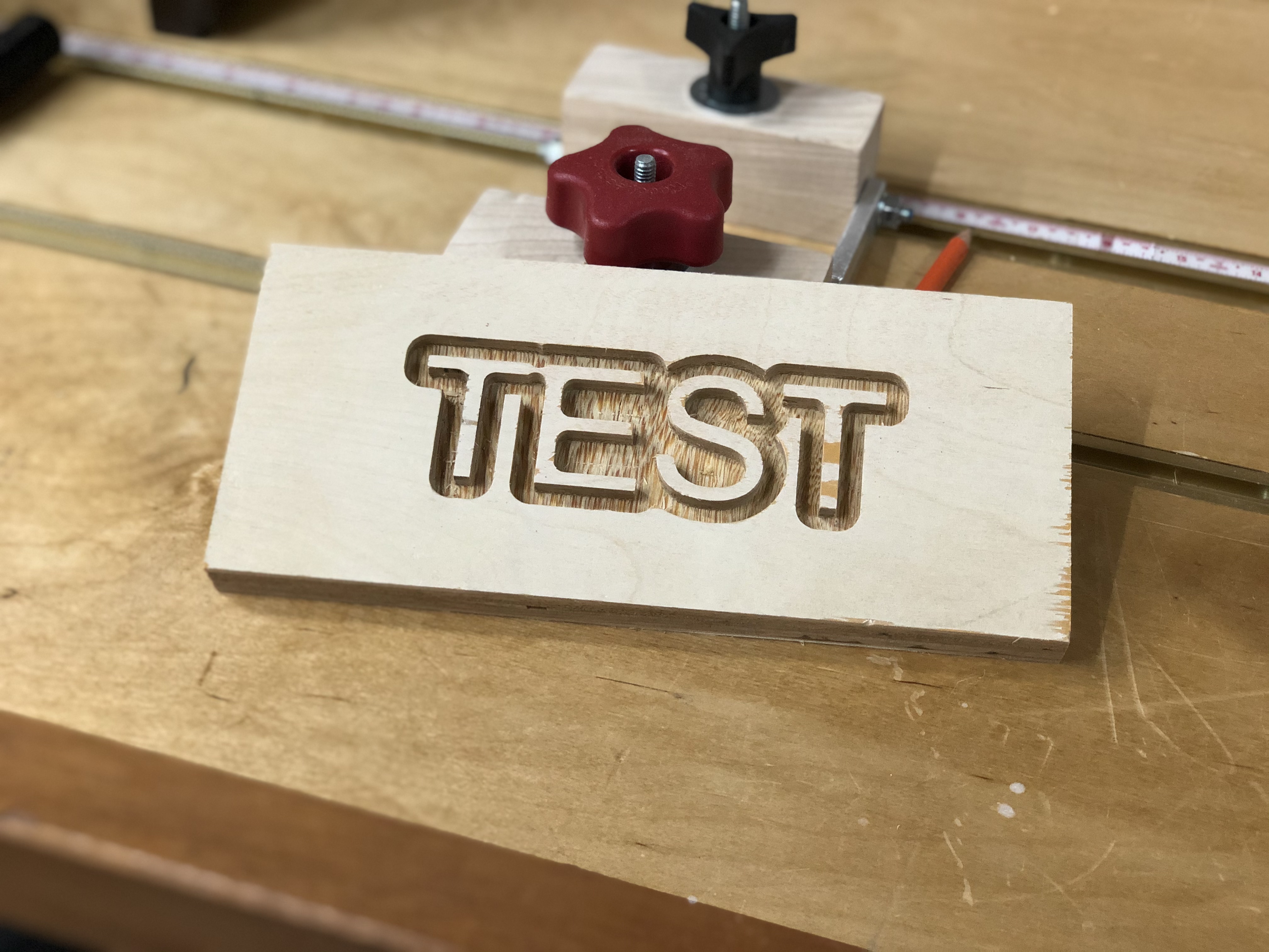
My initial v carve tests seemed ok. I decided to v carve something for real. So I did my normal workflow in CC. Project size and depth was correctly set to my work piece Set start to lower left, as I always do. I setup an advanced V carve, ran the sim and it looked good. I used a #201 for the pocket and 90deg v for the 2nd tool.
I used my bit setter and bit zero to setup the cut. I did Z only on the bit zero. Then zeroed my x and y.
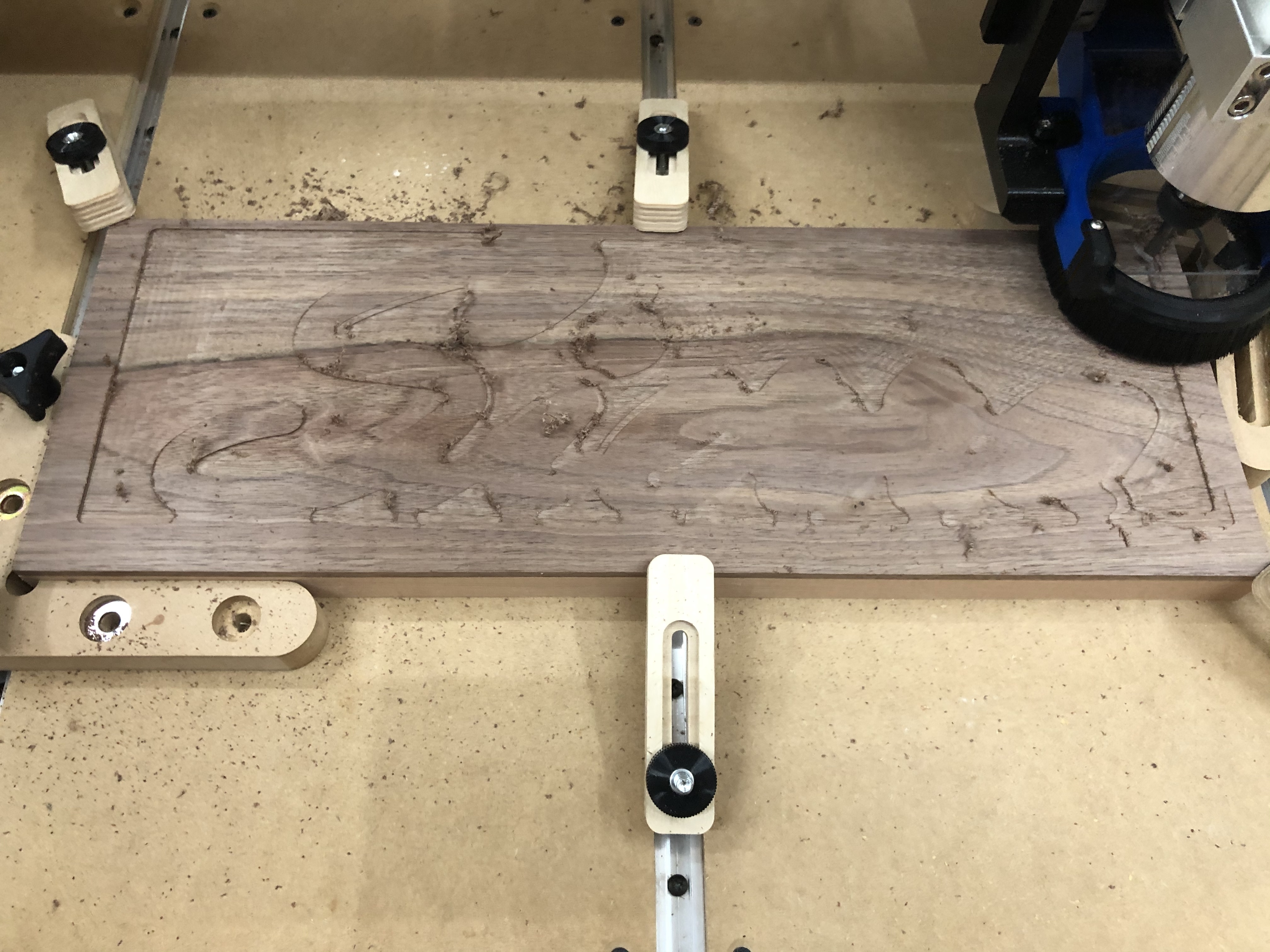
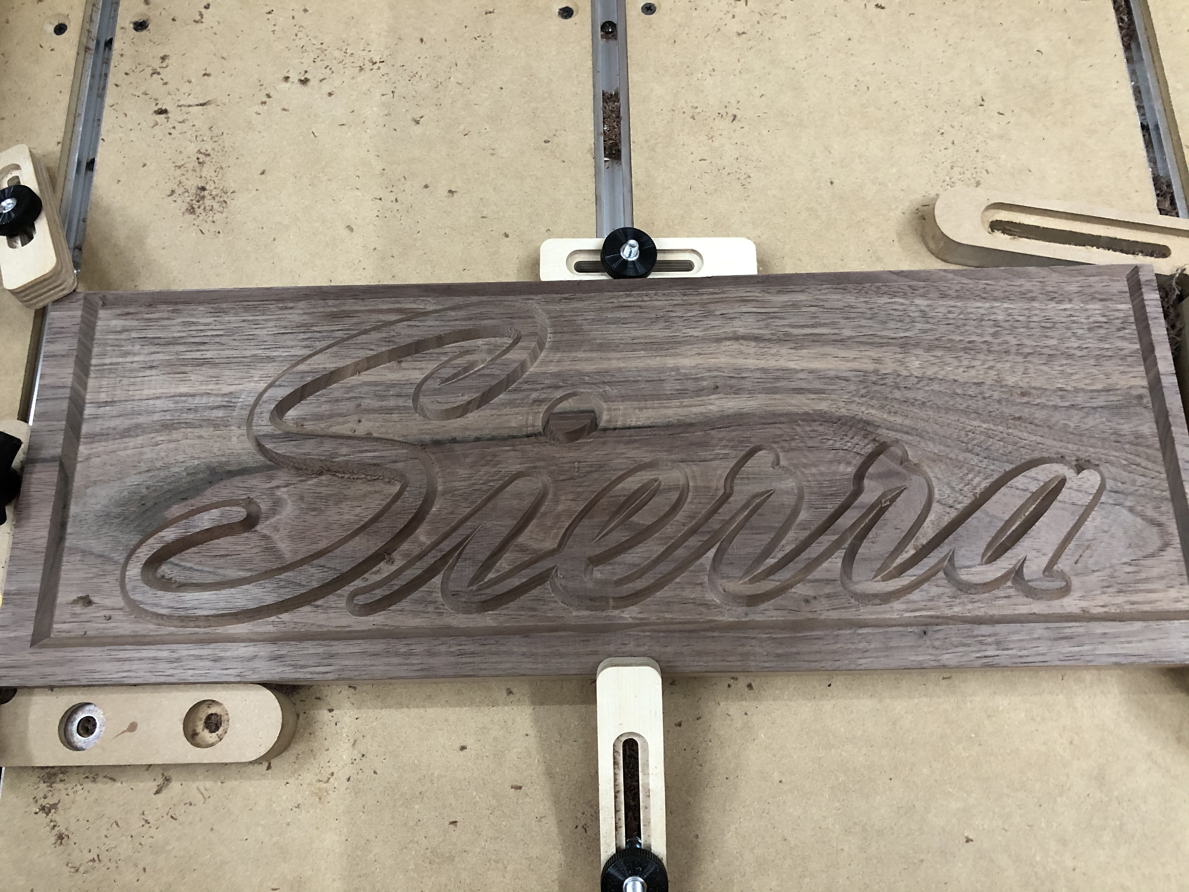
In CC my project is centered to the stock. I have a 1/2” border around the whole thing. Looked perfect in simulation. Here’s the starting cut and the final.
Hi @Vustadumas,
Can you share you G-code file, and c2d file for a quick check?
Can you describe how did you set X,Y zeroes exactly, and how wide the left/right borders are (the wider-than-expected on the left, and the narrower-than-expected on the right)? That could provide a hint (are they 0.625" and 0.375" by any chance?)
Oh I’m positive it’s user error somewhere down the line, hah. I’ll post the cc file and gcode shortly.
For x and y, I zero them after bit zeroing the Z. So I’m not using the bit zero for all 3 axis. It’s been working for smaller things, or larger ones with more margin for error. I’ll do some tests using all 3 axis.
Will, I have definitely not calibrated for belt stretch. I’ll do that as well.
Using a v-bit to set XY by eye is probably just as accurate as using a probe with an endmill. Just make sure that v point is right on the corner. You can easily get sub mm precision (depending on eyes, I guess). That’s good enough for a piece like that.
I’ve seen cases where individuals set zero so the while diameter of the endmill is “inside” the corner of the stock… That would cause this issue.
I use my phone camera zoomed in to about 4x to see where the V bit is, by carefully lining up the bit I can get within ± 0.25mm fairly repeatably (checked with an edge finder).
Here’s the CC file and gcode generated from it. I have a feeling its something machine related. That, or my setup prior to the cut isn’t taking something into account.
So I’ll go into detail of how I’m using the bit zero. Actually, I’ll start with what my machine does when I turn it on and initialize. I initialize the machine, it does the normal back right corner home procedure, then runs to front center for tool change (bit setter). I change the tool, or run it as-is. The machine heads over to my bit setter to check the bit. I watch it plunge down, the bit setter turns red both times. After that runs, it comes back front center. I place the bit zero at the lower left corner of my stock. Z only setup. The full bit zero is on top of the stock, no edges hanging over, its flush at the corner of my stock. I jog over then slowly find what looks to be the most centered on the bit zero’s circle I can get. I hook on the alligator clip and run a probe in Z only. After that, I remove the clip, and go back to the jog screen to zero X and Y in their current coordinates. I leave Z as-is, since the bit zero has already taken the offset in to account. I clear the bit zero from the cutting field.
I then load my file, and start the job. So this part always strikes me as odd, as my bit setter runs again. Maybe I should be loading my job first and foremost? After that, It asks to set the router spindle speed, then my bit runner starts the machine after clicking resume. I think I have to click start one more time? Maybe? Either way, the job starts and runs from that point on.
This was a 3h 48m job. So i’m a bit bummed it didn’t pan out. Not a big deal, I’ll bandsaw some more walnut veneer and try again, once I figure out this issue.
So what I have for stock, is a .25" piece of walnut, laminated to a piece of soft maple. So that was pretty much my intent, to have the letters and frame walnut, but the background be the maple. It worked, and looks just as I thought I would, minus the offset, haha. I did have to adjust my depth and I re-ran the job a 2nd time to get the desired depth correct.
I just measured my bitzero, Center of the circle is .250” in from the edges.
Assuming I understand your process, you zero Z on Center of the circle, with bitzero on top of stock. Then proceed to zero XY at same coordinates?
You should be jogging so the absolute Center of your bit is right on the corner of your stock, so go 250” south and .250” west. That should be your XY Zero.
I didn’t read carefully. @David.Curtis is exactly right…your zero wouldn’t be on the circle engraved on the BitZero, it would be centered over the corner of the BitSetter (also centered over the corner of your stock).
If you’re not using the BitZero to set your XY, just get it out of the way.
I have no clue why C3D put that circle on the top surface. It is very pretty and well made.
Just so anyone that reads this knows, that circle has no intrinsic function to the BitZero gadget!
The circle could cause a probem, though. If you happen to try to zero with a Vbit, and you happen to get the bit’s point right into that circle’s milled out edge, you will not get a good zero. Hopefully, you will see that happen and re-zero.
It’s just a visual cue as to where approximately the endmill should be to start probing (the probing movements kind of assume that it’s near that point, and will move left/down by a certain amount to be sure to clear the sides of the probe)