Hi everyone.
I am building a Senior 20 crank organ, I am having a problem with the tracker bar which should be a straightforward cnc router job
I am trying to cut a D shaped hole 6mm dia and 9mm long on the straight side, and 2mm deep. I also need other smaller D shaped down to 4mm and 4mm long.
I am having sizing problems, either the circular bit is too big or too small,and I cannot get a straight line on the flat side.
Can sombody help me with this, I am a beginner and struggling,
Advice on the cutting tool required would help as well.
Best thing to do is to cut using an undersize endmill as a pocket, leave a roughing clearance, measure the cut, then adjust the finishing pass to cut at the desired size.
Could you post the file you are having difficulty w/?
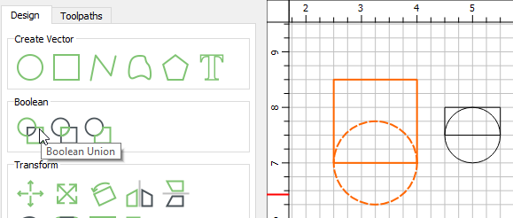
I created a circle and a square/rectangle and boolean union them
I use the grid for my sizes. Set the grid to 1mm, and then View → Snap to Grid
You can also type in the radius of a circle or dimensions of a rectangle when creating it.
Positional accuracy? Dimensional accuracy? (length, width, diameter), or are you talking about getting the corner as sharp as possible?
Not sure what this thing does in an organ. I guess it has something to do with airflow, or is it part of the sound generation? Either way, is it something that needs to be fine tuned? Something you would do by hand?
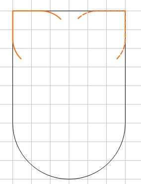
Generally the larger the tool, the more stable it will be & inherently produce greater accuracy. So I would remove the bulk of the material with as large a tool as I could. 1/8", 3mm…
And then use 1 or more smaller tools to get into the corners left by the larger tool.
Carbide Create doesn’t automatically do “Rest Milling”, but you could do it manually.
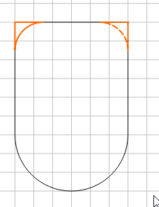
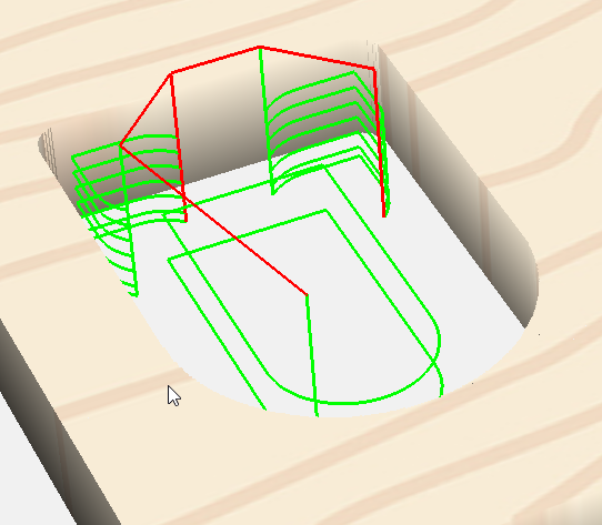
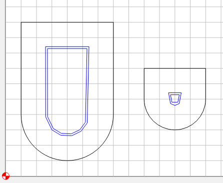
If you cut your 6x9 slot with a 1/8" or 3mm tool, you would be left with these 2 corners
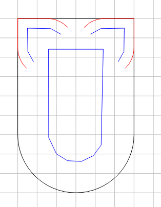
I would want a lead in / lead out for my 1mm cutter, and I want to make sure it starts & ends off the material, so I’ll make an open vector to contour cut
The tracker bar has a paper roll, with holes punched in it to play the notes. Air pressure flows through the holes and is piped to flutes via the tracker bar.
“…make an open vector to contour cut.” And this only cuts one side of the line? How does it distinguish inside from outside, is that trial and error or that one side is more closed in?
I’ve been making closed pockets for detail cutting. I like that your method eases in.
You can cut Inside/Left, Outside/Right, or No Offset (on the line)
Yes, it was trial & error for which side is left or right. Internally each open vector has a beginning & end.
Left will cut on the left side (climb cut), and Right on the right side (Conventional Cut).
I wanted to climb cut so set it to Inside/Left
I got lucky with the first vector & it cut inside the shape. The other one cut outside, so I knew the beginning of the vector was on the wrong end. I mirrored the vector & then rotated it and now the path was “Left” and inside the corner.
 Tracker Bar Construction")