Thanks for the template suggestion.
I started out by guessing the sizes. Would be easier if you told me your desired sizes.
I guessed 8.6 x 12 x 3/4".
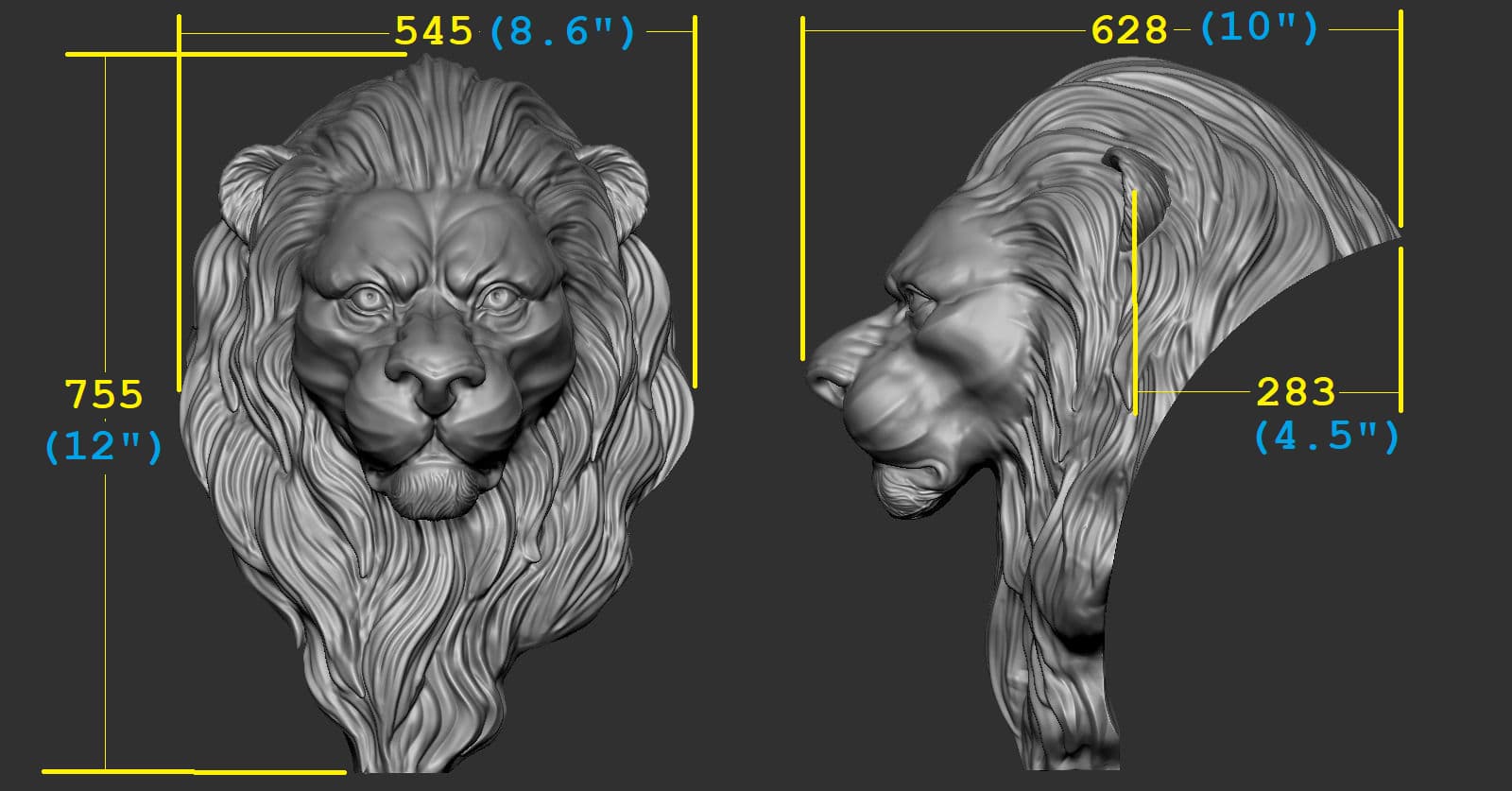
Then I measured the STL so I knew what was going to come in. 8.6 x 12 x 10"
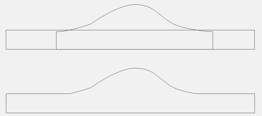
I also determined the silhouette of the STL and measured what would carve, and what would just result in vertical walls. I came up with 0.55" of carve & 0.45" of vertical wall.
You have no real way to do this, other than looking at the side view of the STL on the sight where you got it and interpolating the dimensions based on your desired height.
Here’s the front & side view from the site. If I measure the pixels in an image editor, I get 545 x 755 x 628 pixels. If I want it 12" tall, that converts to 8.6 x 12 x 10". And the 283 distance to the back of the ear becomes 4.5"
I would like at least 1/2" of carve to get as much detail as I can.
So when I import the STL my height parameter will scale the Z dimension of 10" down to 3/4"
That would give me about 0.412 of carve (10 / 5.5 = 0.75 / 0.412). To get a little more carve I’ll lie & bump my stock thickness up to 1". Now that gives me 0.550 of carve, and 0.200 background (0.750 - 0.550 = 0.200). Remember, my actual part is 3/4", I’m modeling 1" and cutting from the top. So the bottom 1/4" of my model is not part of the actual 3/4" stock.
So, in CC I set my stock to 8.6 x 12 x 1".
Then I create a 8.6 x 12" rectangle to build my base
I model a Flat component 0.45" in height.
Then I import the STL at 1" height, and set the merge type to Max, so only the top 0.55" of the STL protrudes out of the base. When you use “Max”, it places the new component without respect to the existing component, then keep the highest point from both components where they overlap.
You can’t go 6", so you’ll have to compromise. Give me your desired dimensions, and I’ll do the math for you. ![]()
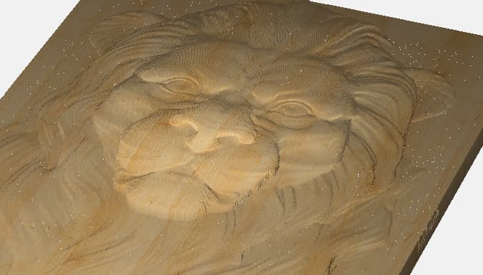
This is a 1/32 ball with 0.008 stepover on my part. Make it a bit taller and the detail will be deeper.
4 Likes
To say “You’re the MAN” is FAR from even getting to how great your are at helping with this AND explaining how your got there.
THANK YOU
I’m cutting as we speak and I have printed off your explanation for future reference. VERY WELL DONE!!
4 Likes
OK. Uncle.
Seems that I either need to get longer length of cut bits (1"+) or calculate something different. I have cut the shape of the lion head with a depth as suggested of 0.5 at the highest point and still get some but not enough detail. Sort of looks like “…as looking though a glass dimly”. So while I might make it work with the caveat of a glass, not what I would really like to get at.
I do have the ability to work with as much as 4 or 5" of wood depth, I don’t think that would work on the 3XXL anyway and that would be one heck of a big plaque for sure .
Can you calculate something that can get more detail but not require really long cut length bits?
I guess I’m learning a lot about what I can’t do with my machine and bits. Not if I can learn to dial back my expectations I might get the results I’m looking for.
As they say, nothing ventured…
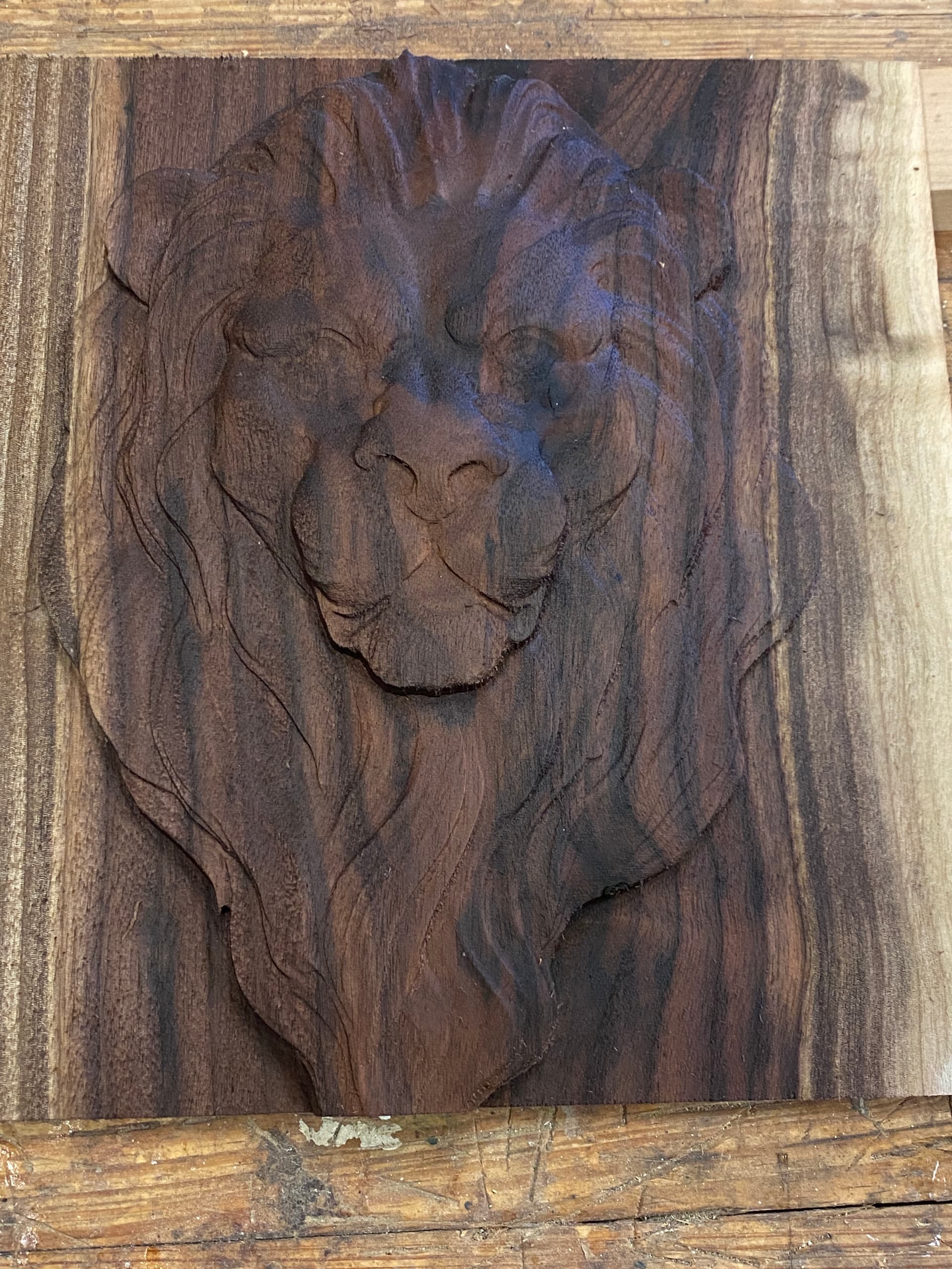
So here is what it ended up looking like without finish. I’ll probably us Boiled Linseed oil on it for finish and add a frame of either Black Walnut or even Cherry.
I may cut another if I can figure out how to get more detail without having to have a 10" high board and a 25K CNC machine. ![]()
@Frank246 - Can you change just the Z height without having that change linked to X and Y in CC PRO?
I’m asking to clarify, for myself from 1d Tod’s post a couple of days ago:
I believe there are some STL converters available that might be able to change the Z, while leaving XY alone.
CC scales the Z dimension separately from the X & Y. X & Y use the workpiece or any vector you have selected when you import the STL. Z uses the “height” parameter in the modeling dialog.
Frank, you should not need a longer cut length bit unless you really want a tall vertical wall on the sides of the lion. There is a limit to how much detail you will get based more on the smallest diameter tool, and the stepover. And of course you can’t get any more than what’s in the STL.
Lighting makes a big difference too. Rotate it around with a single light source to see the contrast between the different heights of the material. I think on lighter colors you will see more contrast as well, since the shadows are much darker compared to the lighted surfaces.
Honestly, that last cut looks really good to me. When the model has sharp concave corners, you will never get quite as sharp an image when you cut with a ball mill. But you should be able to get close.
This is the reason the simulation doesn’t look as sharp as the 3D model. It ‘softens’ up those sharp corners & blurs them a bit.
What is your desired size? And the minimum thickness of the background? I will give you the numbers you need. ![]()
1 Like
@Frank246 - Here’s a version that I ran through Aspire. I set the total model depth at 2.5" and then saved with a flat back, which makes it more of a plaque rather than a mask. Try inserting this one and see how it looks. The file size turns out a bit smaller due to the loss of backside detail.
LH2.zip (3.1 MB)
Here’s what it looks like in Aspire:
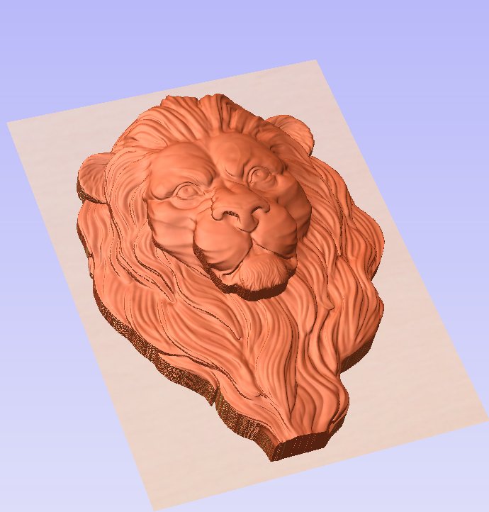
1 Like
Mike: The rendering you show is great. However, I don’t seem to get that same definition in CCPro. If I can get to what you are showing as a final cut that would be fine.
As a plaque I can mount to another backer and then frame for sure.
Todd: Ideally the size of 10"x10" works fine and the height of any straight edge can’t be over about 0.42 based on the bits I currently have. If we can calculate that it might be just perfect. Thanks
You guys are awesome!!
As a side note, is the 1/32 ball the best bit or should I be using something else to get more detail?
Thanks
Frank - Yes, a 1/32" ball should work great.
By raising the Z disproportionately to the XY, the detail level (or depth of detail) is increased, which should help the finished look.
Note the area below the chin and the step there that has been increased by the Z increase. Since Aspire allows separating the X, Y and Z, one is able to stretch the STL in any given direction.
If you want to remove the area below the chin, ears etc. then you might take a look at the methods of @DennisVanHoof. He’s a master at overcoming technical hurdles to create beautiful art!
Try this file. No math necessary, I trimmed it to a flat plane.
1 Like
Thank you. The new file looks very much like what I wanted to get to. I’ll give it a try tomorrow and see.
Question if I may:
Should I go ahead and get the Aspire S/W if this is the type of plaques I might want to pursue in the future as maybe easier to manipulate than CCPro?
I would try CC PRO and Aspire, pretty sure both currently have a free trial. Aspire is very expensive, but there are a lot of support videos available and it’s software for art, not engineering. Fusion 360 would be the way to go there.
CC is being developed very rapidly with, IMHO, some of the best support available!
Right on Aspire being very expensive. Out of my league for sure.
I do have CCPro and hopefully as I learn more about STL and setting the Z depth I can keep getting the look that I want on future work.
THANKS
With all your help, I finally have a cut that looks pretty good. Finished with lacquer

and now need to frame.
THANKS everyone for ALL the help. Would never have made it this far without it.
7 Likes
Great job Frank, your persistence really paid off!
This topic was automatically closed after 30 days. New replies are no longer allowed.