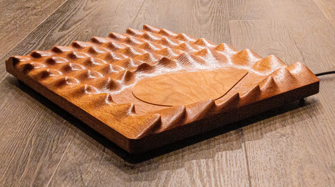
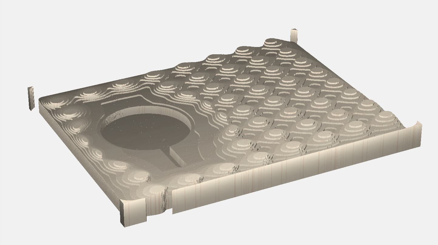
Forgive me if this has been exhausted, but I’m curious about the default speeds and feeds. I am attempting to create this valet. It’s about 340mm x 260mm. I imported the STL and simulated a rough 3D pass with a 1/4" end mill. I used the default settings in the database of Carbide Create and it estimates a whopping 521 minutes!! Does this sound right? #251 End Mill selected from the Hardwood category database within Carbide Motion
Stepover: 0.125"
Depth per pass: 0.04"
Plunge rate: 12.0
Feed rate: 60
RPM: 18000
I’m using a Shapeoko Pro XXL with the Carbide 3D router.
Does everyone else use the default settings? Is this one of those things where I just need to start it in the morning, go to work, come home, and wait for it to finish? LOL
You should try on a practice piece, but the CC settings are very conservative. As a starting point, I’d try a DOC of at least .080", and a feedrate of 100 ipm, but cut the step over a bit, say to .100".
This is great to know. I was wondering if these were conservative. So as a test for simulation time, I made the changes you suggested and I believe the feed rate is really what helped - 91 minutes (vs 521).
Next question. My simulation shows that everything is being cut all at once (the contours, the pocket for the charger, and the overall valet outline). Since I’ll be using both an end mill and a ball mill (for finishing), how can I get it to run one pass to rough in the contours and pocket and then run another finishing pass JUST for the contours? Finally, a final pass to cut out the overall perimeter? (Sorry, I’m still learning Carbide Create and I didn’t see this in the Tutorial section).
I believe if I can run 3 separate tool paths, I can cut time. As it is now, if I run a finishing pass, it’s again going over the entire image (if that makes sense).
Followup question:
In my first roughing pass, the 1/4" end mill roughs in the shape above, roughing in the contours and cutting out the overall perimeter. If I then run a finishing pass, does it again cut out around the perimeter, seeming cutting into air?
I think it would based on your description. So, if you draw the outer border as one vector and then a circle around your pocket and pick both as the definition for the finishing pass then I believe it will skip the circle.
You can look at the tool paths in the simulation view to try and figure that out. In some cases you may need to disable some paths so you can see what is really going on in that simulation view when things are busy.
Here’s where I’m getting held up. (And I apologize for not understanding better - I’m still learning).
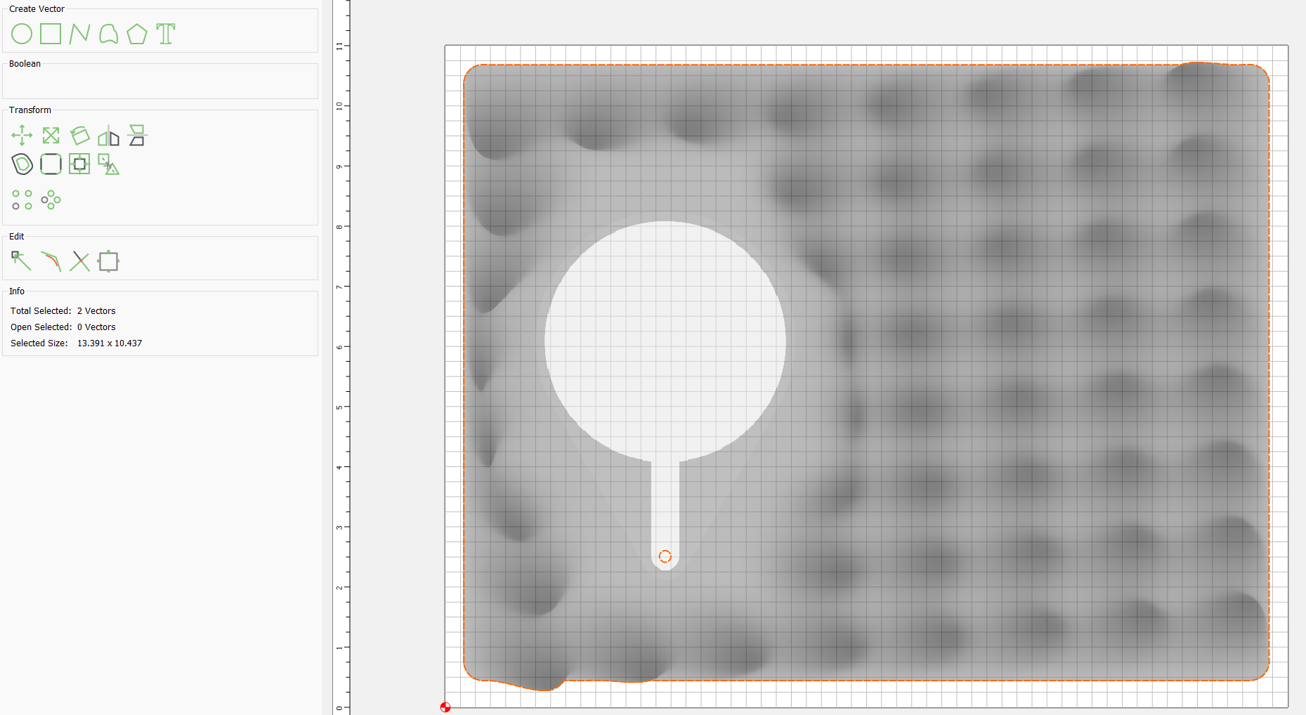
I set up my job parameters and then selected to Import STL. I set my scaling and clicked Done.
As you can see, the overall image is imported. When I select the image, there are 2 vectors, the overall perimeter and a smaller circle within the pocket. I believe these are vectors that establish what gets milled all the way through. The overall perimeter would get cut out and the smaller circle gets milled through because that’s the hole for the cord to the charger that gets placed inside the pocket.
If I draw an offset around the outside for the cut out, then there are 3 vectors. I’m getting lost in the “if you draw the border as one vector and then a circle around your pocket and pick both as the definition for the finishing path…” part of your explanation. Do I have to manually draw a perimeter? Can I not select the perimeter and copy it?
Ideally, I would like to be able to cut all of it with the roughing pass. This would cut out the perimeter, the pocket, and the rough contours (like the image above). Then, I’d like for the finishing pass to ONLY go over the contours and NOT the outside perimeter. I’m thinking there needs to be layers in order to do this? If so, how do I copy the perimeter and make it its own layer?
I thought you were trying to skip the large hole. I’m not sure what is on the outer perimeter to skip.
So, if you select the vector for the outer perimeter and the circle for the pocket and define the finishing pass it should run between the perimeter and the circle.
If you don’t want it going all the way to the edge select the vector on the outer perimeter and create an offset on the inside by the amount you want to skip.
Sorry I am not at my machine with CC now or I would mock something up.
I did have an issue last weekend doing a roundover on the outside of a piece and the bit wanted to go all the way to the bottom of the stock on the outside rather than stopping just after the roundover is completed. Is that what you mean?
In my head, an ideal milling would be that with a 1/4" end mill, everything gets a rough pass. When I say “perimeter” I mean the overall finished dimension of the valet. The first rough pass uses the flat part of the end mill to cut out the perimeter, cut out the pocket in the middle-left part of the valet, and a rough pass of all the contours. Then, a finishing pass with a 1/8" ball mill can finalize only the contours. Meaning, I don’t want the ball mill to mill the perimeter (that was already cutout by the 1/4" end mill) nor do I want it to touch the pocket. I only want the finishing pass to smooth the bumps/contours.
Maybe I need to have a 3D rough pass for the contours and pocket, a 2D contour pass to cut out the perimeter, and a 3D finishing pass (or two) for the smoothing of the bumps/contours? I don’t think I need a roundover.
I did manage to figure out how to copy the outside vector and make a layer of just that.
I typically save the cutout for the final step since the part is more prone to movement. But in a recent job I did create a
Pocket on the outside that was lower than anything touched by the 3D passes to provide but clearance since I was using a tapered ball nose. Then I did the 3D and then came back and started at the level of the pocket and went down for the final contour.
If you inset that outer vector and select that and the hole for your 3D pass does it do what you want?
Yes.
Rough 3D selecting only the outside perimeter vector as the boundary. This will also rough out the pocket.
Finish 3D selecting the outside perimeter AND the keyhole/pocket vectors
Contour inside the pocket
Contour outside the perimeter
That requires 2 toolchanges, but I think you will get a better finish by doing the contours last.
If you really want to reduce the toolchanges, do the finish 3D last.