Hi there. i have now managed to put on a Vevor 230v spindle and control it from inside the Warthog controller which is not optimal. do anybody know if the spindle connecotr on the fornt is an opencollotor output from an optocoupler or ?. secondly do anybody know the pindout of the other connecotr and what they can be used for. Best regards Palmqvist
Why is it not ideal to use the interior warthog controller?
Hi Lars,
I have the Carbide VFD, and it has given me no problems. However, a friend then offered me his used HY 110V VFD and air-cooled spindle (almost identical to the Carbide one) when he moved on to 220V and bigger things involving fluid coolers. Now I have a spare just in case of future problems, provoking a look into this whole can of worms.
The spindle connector carries 24VDC (red) and ground, plus the output. On the 'scope, it looks like it is the output of an opto-isolator with a pull-up resistor to 5V inside the controller. While the duty cycle of the 8 Khz PWM signal follows the requested speed pretty well, the rise time is terrible, leading to inaccurate integration. There is also a small positive offset. To make things worse, its output impedance is high enough that the HY VFD’s analog input loads that signal down to under 3 volts peak (these all make me wonder if the controller opto’s led is being seriously under-driven).
I too am wary of bringing a dirty outside connection from a device producing all kinds of noise directly onto a processor pin on the main controller without even a buffer in between, let alone real isolation. I’d rather condition that provided “isolated” output - even though it’s not ideal. I’d also rather keep that box closed - and my warranty intact.
An NPN transistor and a couple of resistors acting as a switch, followed by a second similar stage to invert the cleaned PWM signal works pretty nicely. Both powered from the HY VFD’s 10V reference output. A pot trims the output to a pretty clean 5V PWM. They all sit on a little PCB inside the HY inverter case.
1 Like
Hi Kevin.
It would be nice if we could talk on skype or teams ?. I have a small inverboard hook up to the internal pin’s and that work, but as explained would like to move it to the outside connector, i think the missmatch is because the converters normally expect 1-3khz or 7.3khz and a duty cycle. i have some pictures of the inside let me trace the output of the octocouplers , and it is actually smithtriggers so a converter to ttl level i gues , it is an h11l1
Hi Lars,
While I work in IT and my work-owned remote computer is fully set up and active for Teams, my personal one has neither camera nor microphone attached - deliberately!
The HY VFD inverter accepts an analog voltage of either 0-5V or 0-10V, a current loop at either 0-20mA or 4-20 mA or a combination of the two. A straight DC input works just fine. It can filter a PWM signal to provide the DC voltage, probably just on a simple RC filter. That is pretty much carrier frequency insensitive, but that does depend on integrating the area under the curve - so a long rise-time impacts its accuracy significantly. The actual waveform coming from the Carbide controller connector looks like this (at S20000):
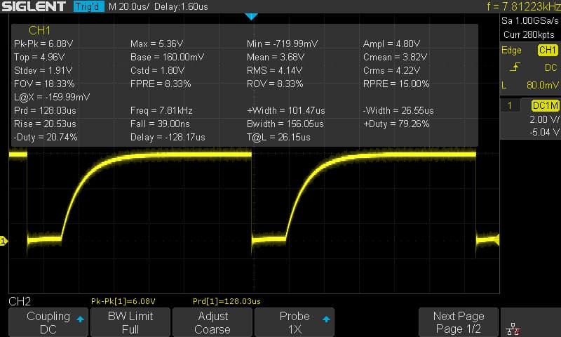
Squaring up the waveform from the Carbide controller output with a comparator, low-threshold Schmitt, or a simple transistor switch does work well - and it also addresses the relatively high output impedance that makes it incompatible with the HY analog input as-is.
Alternatively, the HY VFD accepts RS485 Modbus control, and I have used that successfully with a different home-built controller. That is on a completely different machine based around the ESP32 and open-source FluidNC. (FluidNC has modular software support for simple cheap RS485 converters based around the MAX485. The GRBL 1.1-based Carbide controller doesn’t offer it).
Ok Wauv
I guess I need to measure properly tomorrow.
, I am using a spindle from vevor which need dc input, and it also have a digital mode which I don’t know what is, perhaps pwm.
Today I hav used this device to convert to dc, it is not precise but close when I set 16000 rpm I get 13987.
I can se the device they are using is an optocoupler which a tel smith trigger output which accepts 2-15v supply and gives you til out.
I will try and hock up the connector and see if how it goes.
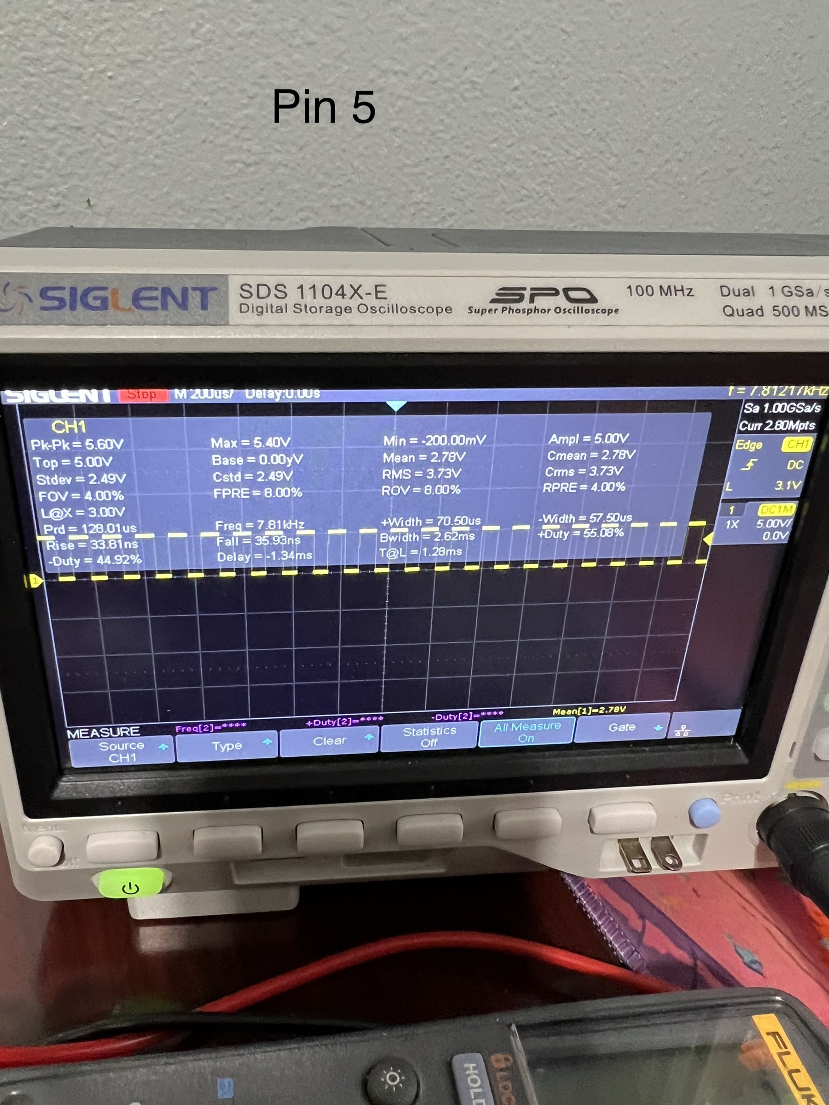
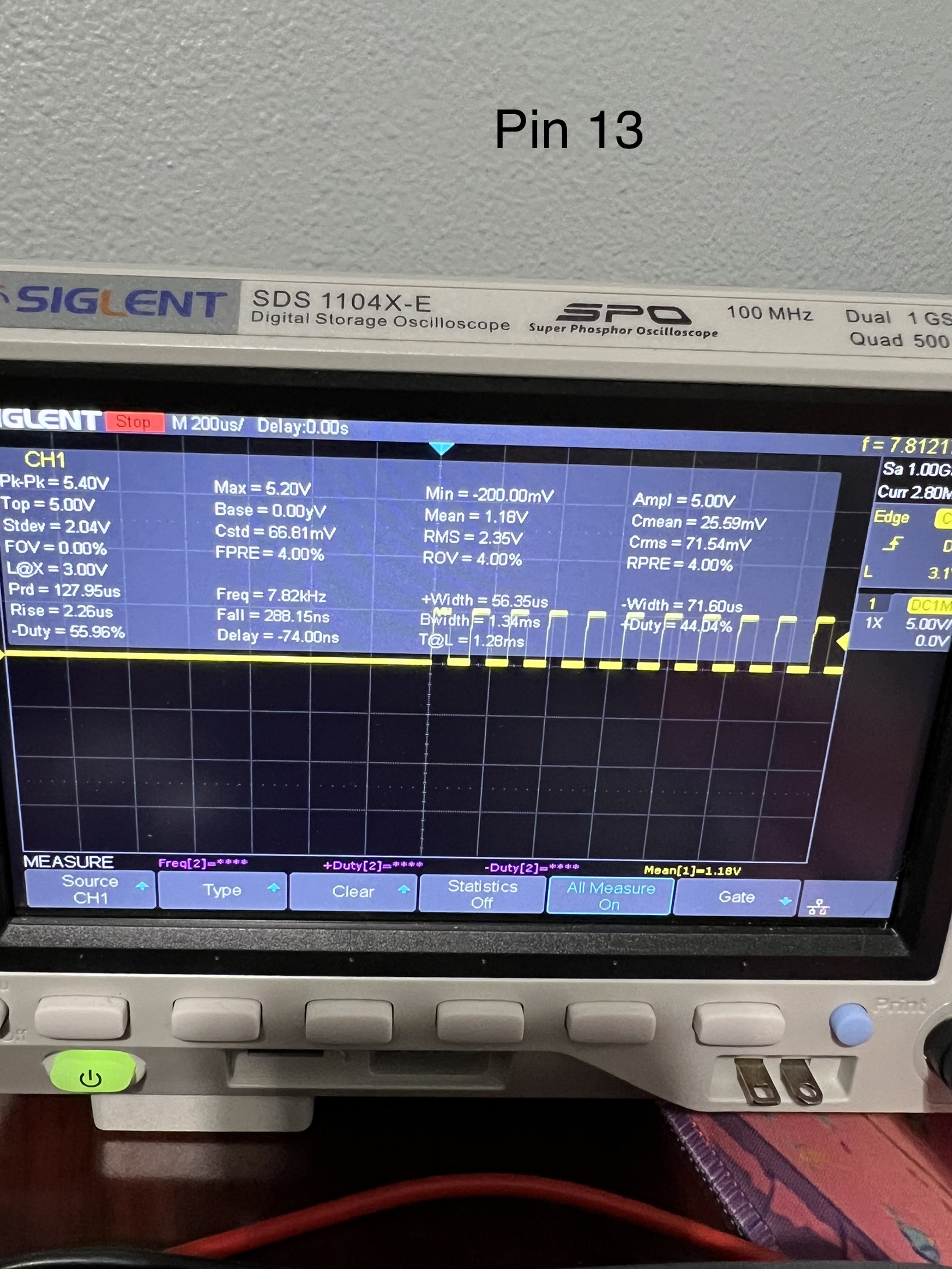
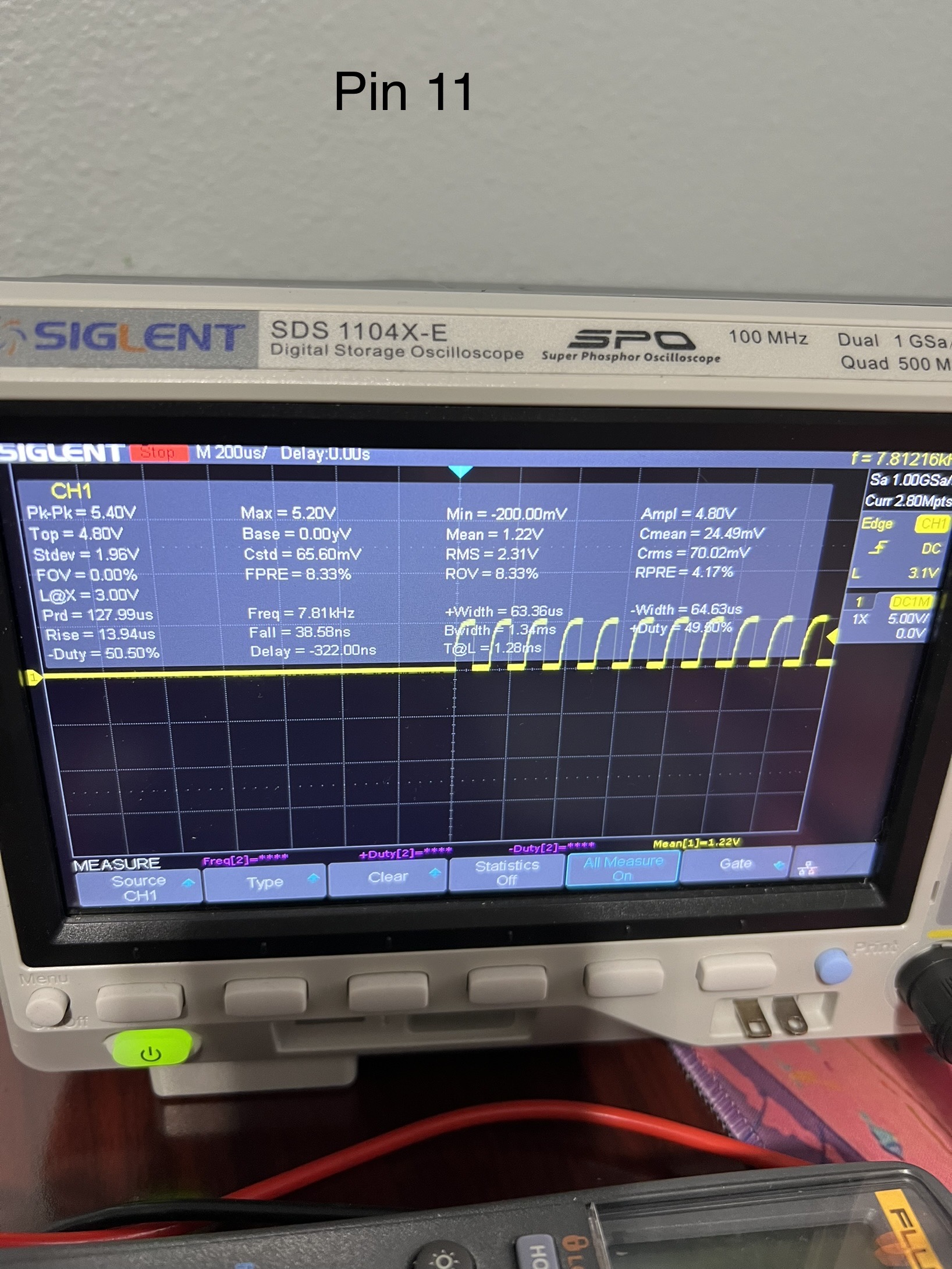
I have not traced out the entire board but from what I can tell the warthog v2 PCB does not use a optocoupler for the PWM signal. Instead the MOSI pin from the Atmel 328p is traced to U3( what I believe is a TI SN74F38 NAND Buffer) on pin 5. The output of U3 pin 6 then goes into U3 input pin 13 and comes out of U3 output pin 11 which then runs through a 100 Ohm resistor with a capacitor in parallel to ground to finally arrive at the spindle PWM pin.
I do not see any optocouplers being used for the PWM signal unless I missed it.
A quick look around for Vevor spindles/VFDs shows that Vevor have used a variety of Chinese suppliers including Huanyang. Most of those VFD manuals say that they can use analog inputs (as I described above) which are 0-5V or 0-10V, but a 5V amplitude PWM signal of low enough output impedance (so the VFD doesn’t pull down the peak voltage) will work fine without conversion. That’s what you’re using off the internal pin on the board. Internally in the VFD, that PWM signal (ideally a square wave) is integrated to a DC voltage by a simple RC filter. “Digital” varies, though RS485 Modbus is pretty commonly used.
We have gone down the same path - I tried one of those little “PWM converter” boards (but on the output, not the internal pin) and wasn’t greatly impressed. Lots of complexity for a very simple task that a transistor or two and a few resistors can do. The main thing it was doing in my case was buffering to a lower output impedance. The Schmitt doesn’t trigger till well up that rise-time curve
Two very simple 2N2222 common emitter stages in series, loaded by 560R collector resistors with 10K input resistors on the bases. The power is from the VFD 10V reference line, and the VFD is set for 0-10V analog input. At these input levels, they’re fully switched on/off very low in that rise-time, close to the 0.6V junction voltage.
The white and blue wires simply connect digital ground to the forward direction pin, green is analog ground, red is VFD 10V. There is a wire on the underside to the VI analog input.

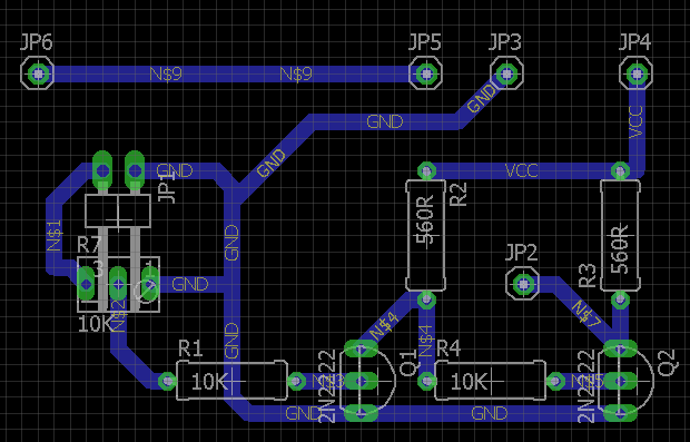
The little board was drawn up in Eagle (version 7 - pre-takeover by Autodesk), converted to G-code by Carbide Copper and cut with a V-bit and a PCB drill bit on the 5 Pro.
Looks like U3 causes increased rise time both times they feed through the chip. Possibly a counterfeit TI chip as the specifications for the real chip is a max of 12.5ns from low to high with a max propagation delay of 50ns. It is also possible that C140 is making the problem worse.
U3 pin 5(from 328p MOSI pin), 33.81ns rise:
U3 Pin 13, 2.26us rise:
U3 Pin 11(to Spindle PWM Pin), 13.94us rise:
It’s worth noting that these findings are intriguing, particularly in light of C3D’s previous statement about the need for signal conditioning from the spindle port due to optocoupler use. However, it’s important to highlight that a properly specified optocoupler should not necessitate signal conditioning, and if anything, it should already condition the signal with a Schmitt trigger.
The post I am referencing above can be found here:
Hi again Kevin.
I dont understand that you have only 2 wires fron the controller dont you need 3 Power for the optocoupler, pwm, ground. please sket what you have made there it look very cooll, i will order some board’s if that’s fine with you. lastly i am using the warthog controller on Shapeoko 5 pro . which have a 3 pin wire ground red and green, and it was me belive that the re and green was wharthog smithrigger power and outputline . i think the kakkie
Thanks i guess the pull ups can just be aplied on the input of the vfd to the supply of the vfd. correct.
and please whats on the 3 pin connector adaptor ground red green.
You only need PWM and ground from the SO5 controller(green and black wire). If you want to use a optocoupler you can power it from the VFD’s 10V supply. In the case of woodworm, he is only using two transistors, four resistors and a potentiometer it looks like(no optocoupler). He is also getting power from the VFD’s 10V supply.
pull ups for what? In your picture you can just connect the red wire to ground in the VFD and the black wire to your voltage input pin. Most VFD’s have their input pins optocoupled already, you might want to check your manual or reach out to the manufacturer.
Hi Again Kevin if it not to much to ask , would you be willing to share diagram and board layout :-).
Lars
Sure,
The schematic and board are very simple prototypes. It’s not at all elegant (but it works well).
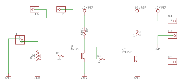
It will output a fairly clean square wave PWM at 0-10V, and the VFD needs to be set to use that.
Only two wires (signal and ground) are carried over from the controller. The input from the controller is on pin 2 of JP1, with ground from the controller on pin 1. The 24 volt line is not carried over.
JP2 through 6 are just solder pads for wires to the VFD screw terminals. JP2 goes to VI (analog input) under the board. JP3 goes to analog ground. JP4 goes to the 10V ref. JP 5 and 6 just connect the FWD (forward direction) and digital ground together. The photo in the other post shows the connections other than VI, which is underneath.
 .
.
The Eagle files for the bottom of the board and for the drill were run through Carbide Copper to generate G-code to isolate the tracks and drill the holes. I can’t upload the Eagle files, but this is pretty simple to re-create in Eagle or similar tools. The NC file is here:
copper (4).nc (25.1 KB)
As always, play at your own risk. I accept no responsibility for your choice to do so or for any consequences from it.
BTW: my 2N2222’s have the flat side opposite to the devices on the Eagle board - verified with a transistor tester. The photo shows the correct orientation for the devices that I have - they’re not in the wrong way ![]() .
.
:-). Your a star thank you will let you know how it goes.
Lars
Just remember that VFDs are dangerous devices. The back inverter board and the back row of connectors for mains input and spindle outputs carry high voltages with enough current capacity to give an instantly lethal shock.
These connections are to the front logic/control board, which works at much lower voltages - but it is only inches from the high voltage side.
I am a embedded hardware engineer originally, so no my way around thanks.
![]()
Not aimed at you particularly, Lars. There are others on the forum who might get tempted to play.
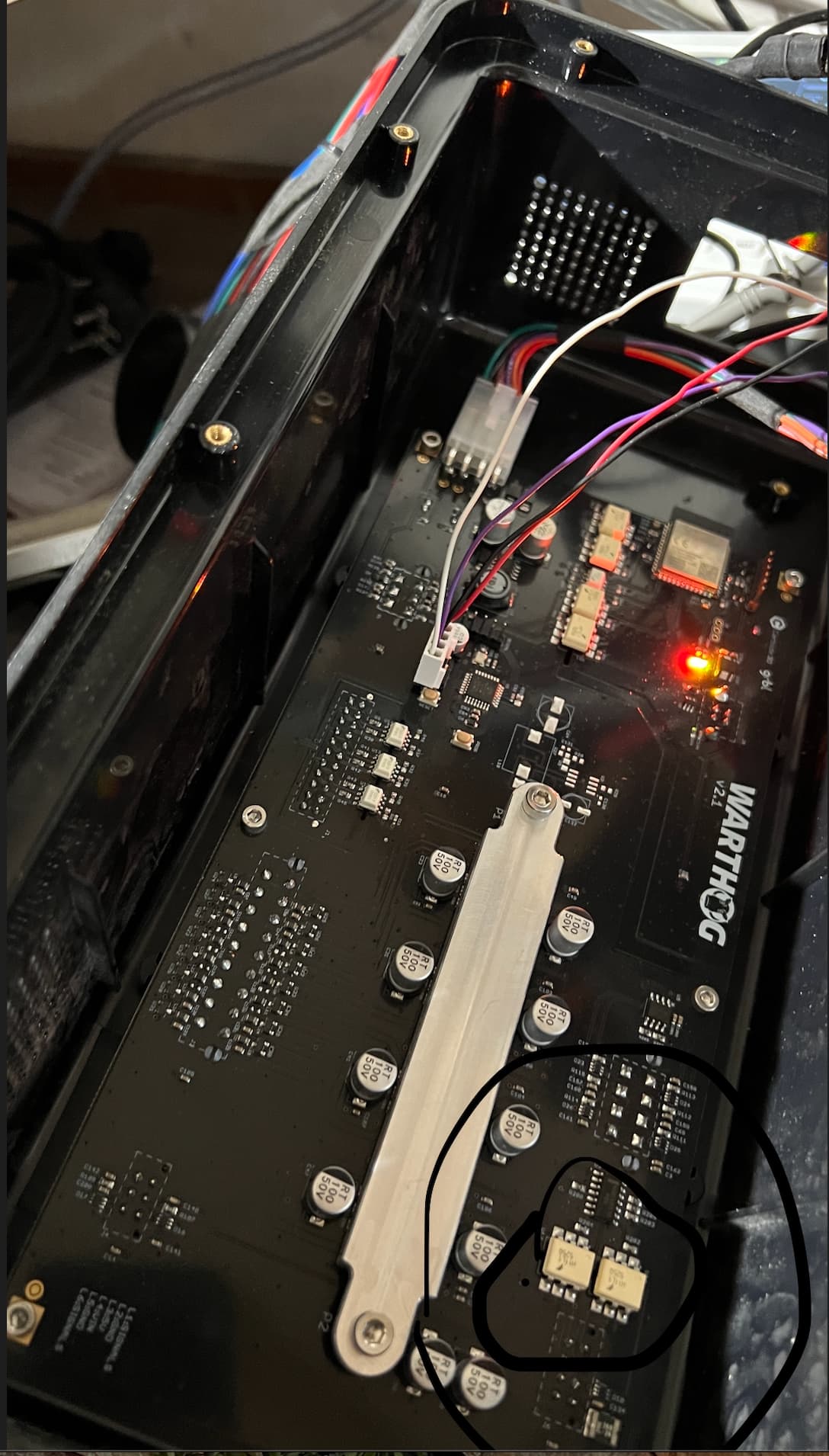
That’s really interesting, Tanner. I’d taken C3D at face value when told this was opto-isolated! So, I took a look at the board (Warthog 2.1, like yours) with the dissecting microscope. Yep, there is no opto-isolation. It actually looks like this, which fits your findings. The little 6-pin “70t” SMDs - D16 and D17 - are almost certainly quadruple ESD Zeners.
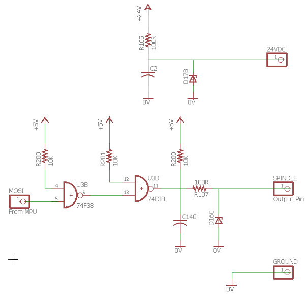
That explains a lot of what is going on. That 74F38 is plenty fast enough (as you saw probing at U3 pin 13). However, the collector load on U3D at pin 11 is 10K (R209), which means that C140 is discharged fast when U3D goes low, but is charging through that resistor when it goes high. Hence the slow rise time and the “high output impedance” - which is the cap draining faster into the HY VFD than it’s being charged via R209.
Re-measuring the rise time (about 22 microseconds) gives an RC time constant of around 15 microseconds - which would fit for a 10K resistor and around 1.5 nF of capacitance in C140 plus strays.
That gate should be able to sink 50 mA easily (max is 128 mA per the datasheet you retrieved), so they could even go down to as low as 100R - and fix both problems!
Question: on an OC NAND gate output feeding another NAND gate’s input, should you also use a pull-up - i.e. between U3B (6) and U3D (13)?
BTW: there is a very similar output circuit on the connector pin opposite the spindle output - but nothing on it when the spindle is active.
1 Like